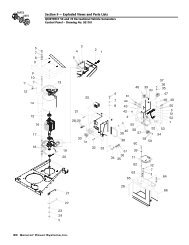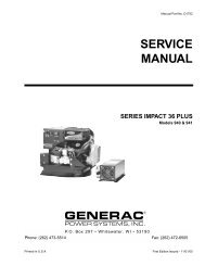
Quietpact 40G Diagnostic Repair Manual Model 4700 - Generac Parts
Quietpact 40G Diagnostic Repair Manual Model 4700 - Generac Parts
Quietpact 40G Diagnostic Repair Manual Model 4700 - Generac Parts

You also want an ePaper? Increase the reach of your titles
YUMPU automatically turns print PDFs into web optimized ePapers that Google loves.
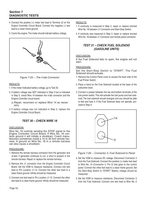
Section 7<br />
DIAGNOSTIC TESTS<br />
4. Connect the positive (+) meter test lead to Terminal J2 on the<br />
Engine Controller Circuit Board. Connect the negative (-) test<br />
lead to a clean frame ground.<br />
5. Crank the engine. The meter should indicate battery voltage.<br />
RESULTS:<br />
1. If continuity is measured in Step 2, repair or replace shorted<br />
Wire No. 18 between J1 Connector and Start-Stop Switch.<br />
2. If continuity was measured in Step 3, repair or replace shorted<br />
Wire No. 18 between J1 Connector and remote panel connector.<br />
Test 31 – Check Fuel Solenoid<br />
(Gasoline Units)<br />
DISCUSSION:<br />
If the Fuel Solenoid fails to open, the engine will not<br />
start.<br />
Figure 7-25. – The 4-tab Connector<br />
RESULTS:<br />
1. If the meter Indicated battery voltage, go to Test 30.<br />
2. If battery voltage was NOT indicated in Step 3 but is indicated<br />
in Step 5, check Wire 14 between the 4-tab connector and the<br />
Engine Controller circuit board.<br />
a. <strong>Repair</strong>, reconnect or replace Wire 14 as necessary.<br />
3. If battery voltage was not indicated in Step 5, replace the<br />
Engine Controller Circuit Board.<br />
Test 30 – Check Wire 18<br />
DISCUSSION:<br />
Wire No. 18 controls sending the STOP signal to the<br />
Engine Controller Circuit Board. If Wire No. 18 contacts<br />
ground it will initiate a shutdown. Coach manufacturers<br />
sometimes install a 15 to 30 foot remote harness.<br />
A ground on Wire No. 18 in a remote harness<br />
can also cause a shutdown.<br />
PROCEDURE:<br />
1. Remove the remote harness connector from the generator and<br />
re-test. If generator continues to run, a short is present in the<br />
remote harness. <strong>Repair</strong> or replace the remote harness.<br />
2. Remove the J1 connector from the Engine Controller Circuit<br />
Board. Set the VOM to measure resistance. Connect one test<br />
lead to Pin Location J1-14. Connect the other test lead to a<br />
clean frame ground. Infinity should be measured.<br />
3. Connect one test lead to Pin Location J1-15. Connect the other<br />
test lead to a clean frame ground. Infinity should be measured.<br />
PROCEDURE:<br />
Set the Start-Stop Switch to “START”. The Fuel<br />
Solenoid should actuate.<br />
1. Remove the Control Panel cover to access the back side of the<br />
Fuel Primer Switch.<br />
2. Place a hand on the Fuel Solenoid located at the base of the<br />
carburetor bowl.<br />
3. Connect a jumper between the top and bottom terminals of the<br />
fuel primer switch. This will activate the fuel pump and fuel solenoid.<br />
The fuel solenoid should energize and you should be able<br />
to feel and hear it. If the Fuel Solenoid does not operate, proceed<br />
to Step 4.<br />
14<br />
Figure 7-26. – Connector 3, Fuel Solenoid to Panel<br />
4. Set the VOM to measure DC voltage. Disconnect Connector 3<br />
from the Fuel Solenoid. Connect the positive (+) meter test lead<br />
to Wire No. 14 (Connector 3, Pin 2) that goes to the control<br />
panel. Connect the other test lead to a clean frame ground. Set<br />
the Start-Stop Switch to “START.” Battery voltage should be<br />
measured.<br />
5. Set the VOM to measure resistance. Disconnect Connector 3<br />
from the Fuel Solenoid. Connect one test lead to Wire No. 0<br />
0<br />
Page 52