Quietpact 40G Diagnostic Repair Manual Model 4700 - Generac Parts
Quietpact 40G Diagnostic Repair Manual Model 4700 - Generac Parts
Quietpact 40G Diagnostic Repair Manual Model 4700 - Generac Parts

You also want an ePaper? Increase the reach of your titles
YUMPU automatically turns print PDFs into web optimized ePapers that Google loves.
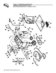
Section 5<br />
ENGINE DC CONTROL SYSTEM<br />
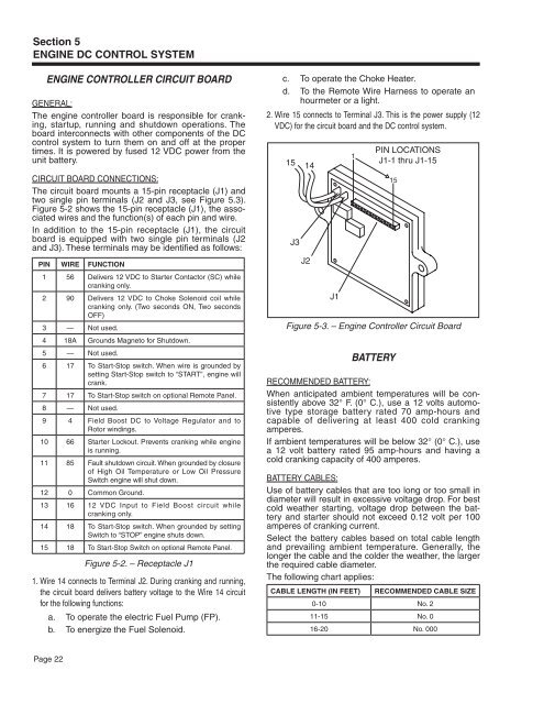
Engine Controller Circuit Board<br />
GENERAL:<br />
The engine controller board is responsible for cranking,<br />
startup, running and shutdown operations. The<br />
board interconnects with other components of the DC<br />
control system to turn them on and off at the proper<br />
times. It is powered by fused 12 VDC power from the<br />
unit battery.<br />
CIRCUIT BOARD CONNECTIONS:<br />
The circuit board mounts a 15-pin receptacle (J1) and<br />
two single pin terminals (J2 and J3, see Figure 5.3).<br />
Figure 5-2 shows the 15-pin receptacle (J1), the associated<br />
wires and the function(s) of each pin and wire.<br />
In addition to the 15-pin receptacle (J1), the circuit<br />
board is equipped with two single pin terminals (J2<br />
and J3). These terminals may be identified as follows:<br />
PIN WIRE FUNCTION<br />
1 56 Delivers 12 VDC to Starter Contactor (SC) while<br />
cranking only.<br />
2 90 Delivers 12 VDC to Choke Solenoid coil while<br />
cranking only. (Two seconds ON, Two seconds<br />
OFF)<br />
3 — Not used.<br />
4 18A Grounds Magneto for Shutdown.<br />
5 — Not used.<br />
6 17 To Start-Stop switch. When wire is grounded by<br />
setting Start-Stop switch to “START”, engine will<br />
crank.<br />
7 17 To Start-Stop switch on optional Remote Panel.<br />
8 — Not used.<br />
9 4 Field Boost DC to Voltage Regulator and to<br />
Rotor windings.<br />
10 66 Starter Lockout. Prevents cranking while engine<br />
is running.<br />
11 85 Fault shutdown circuit. When grounded by closure<br />
of High Oil Temperature or Low Oil Pressure<br />
Switch engine will shut down.<br />
12 0 Common Ground.<br />
13 16 12 VDC Input to Field Boost circuit while<br />
cranking only.<br />
14 18 To Start-Stop switch. When grounded by setting<br />
Switch to “STOP” engine shuts down.<br />
15 18 To Start-Stop Switch on optional Remote Panel.<br />
Figure 5-2. – Receptacle J1<br />
1. Wire 14 connects to Terminal J2. During cranking and running,<br />
the circuit board delivers battery voltage to the Wire 14 circuit<br />
for the following functions:<br />
a. To operate the electric Fuel Pump (FP).<br />
b. To energize the Fuel Solenoid.<br />
c. To operate the Choke Heater.<br />
d. To the Remote Wire Harness to operate an<br />
hourmeter or a light.<br />
2. Wire 15 connects to Terminal J3. This is the power supply (12<br />
VDC) for the circuit board and the DC control system.<br />
PIN LOCATIONS<br />
1<br />
15 j1-1 thru j1-15<br />
14<br />
j3<br />
j2<br />
j1<br />
Figure 5-3. – Engine Controller Circuit Board<br />
15<br />
Battery<br />
RECOMMENDED BATTERY:<br />
When anticipated ambient temperatures will be consistently<br />
above 32° F. (0° C.), use a 12 volts automotive<br />
type storage battery rated 70 amp-hours and<br />
capable of delivering at least 400 cold cranking<br />
amperes.<br />
If ambient temperatures will be below 32° (0° C.), use<br />
a 12 volt battery rated 95 amp-hours and having a<br />
cold cranking capacity of 400 amperes.<br />
BATTERY CABLES:<br />
Use of battery cables that are too long or too small in<br />
diameter will result in excessive voltage drop. For best<br />
cold weather starting, voltage drop between the battery<br />
and starter should not exceed 0.12 volt per 100<br />
amperes of cranking current.<br />
Select the battery cables based on total cable length<br />
and prevailing ambient temperature. Generally, the<br />
longer the cable and the colder the weather, the larger<br />
the required cable diameter.<br />
The following chart applies:<br />
CABLE LENGTH (IN FEET)<br />
RECOMMENDED CABLE SIZE<br />
0-10 No. 2<br />
11-15 No. 0<br />
16-20 No. 000<br />
Page 22