Quietpact 40G Diagnostic Repair Manual Model 4700 - Generac Parts
Quietpact 40G Diagnostic Repair Manual Model 4700 - Generac Parts
Quietpact 40G Diagnostic Repair Manual Model 4700 - Generac Parts

Create successful ePaper yourself
Turn your PDF publications into a flip-book with our unique Google optimized e-Paper software.
Section 7<br />
DIAGNOSTIC TESTS<br />
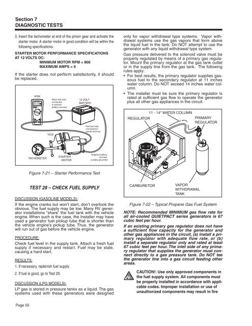
3. Insert the tachometer at end of the pinion gear and activate the<br />
starter motor. A starter motor in good condition will be within the<br />
following specifications:<br />
STARTER MOTOR PERFORMANCE SPECIFICATIONS<br />
AT 12 VOLTS DC:<br />
MINIMUM MOTOR RPM = 800<br />
MAXIMUM AMPS = 9<br />
If the starter does not perform satisfactorily, it should<br />
be replaced.<br />
VOM<br />
VICE<br />
Black test lead<br />
connected<br />
to positive<br />
battery terminal<br />
12 VOLT<br />
BATTERY<br />
Red test lead<br />
connected to<br />
starter terminal<br />
only for vapor withdrawal type systems. Vapor withdrawal<br />
systems use the gas vapors that form above<br />
the liquid fuel in the tank. Do NOT attempt to use the<br />
generator with any liquid withdrawal type system.<br />
Gas pressure delivered to the solenoid valve must be<br />
properly regulated by means of a primary gas regulator.<br />
Mount the primary regulator at the gas tank outlet<br />
or in the supply line from the gas tank. The following<br />
rules apply:<br />
• For best results, the primary regulator supplies gaseous<br />
fuel to the secondary regulator at 11 inches<br />
water column. Do NOT exceed 14 inches water column.<br />
• The installer must be sure the primary regulator is<br />
rated at sufficient gas flow to operate the generator<br />
plus all other gas appliances in the circuit.<br />
REGULATOR<br />
11 - 14" WATER COLUMN<br />
PRIMARY<br />
REGULATOR<br />
TACHOMETER<br />
STARTER<br />
MOTOR<br />
Negative battery<br />
terminal<br />
suitably grounded<br />
Figure 7-21 – Starter Performance Test<br />
Test 28 – Check Fuel Supply<br />
DISCUSSION (Gasoline <strong>Model</strong>s):<br />
If the engine cranks but won’t start, don’t overlook the<br />
obvious. The fuel supply may be low. Many RV generator<br />
installations “share” the fuel tank with the vehicle<br />
engine. When such is the case, the Installer may have<br />
used a generator fuel pickup tube that is shorter than<br />
the vehicle engine’s pickup tube. Thus, the generator<br />
will run out of gas before the vehicle engine.<br />
PROCEDURE:<br />
Check fuel level in the supply tank. Attach a fresh fuel<br />
supply if necessary and restart. Fuel may be stale,<br />
causing a hard start.<br />
RESULTS:<br />
1. If necessary, replenish fuel supply.<br />
2. If fuel is good, go to Test 29.<br />
DISCUSSION (LPG <strong>Model</strong>s):<br />
LP gas is stored in pressure tanks as a liquid. The gas<br />
systems used with these generators were designed<br />
CARBURETOR<br />
VAPOR<br />
WITHDRAWAL<br />
TANk<br />
Figure 7-22 – Typical Propane Gas Fuel System<br />
NOTE: Recommended MINIMUM gas flow rate for<br />
all air-cooled QUIETPACT series generators is 67<br />
cubic feet per hour.<br />
If an existing primary gas regulator does not have<br />
a sufficient flow capacity for the generator and<br />
other gas appliances in the circuit, (a) install a primary<br />
regulator with adequate flow rate, or (b)<br />
install a separate regulator only and rated at least<br />
67 cubic feet per hour. The inlet side of any primary<br />
regulator that supplies the generator must connect<br />
directly to a gas pressure tank. Do NOT tee<br />
the generator line into a gas circuit feeding other<br />
areas.<br />
$<br />
CAUTION!:<br />
Use only approved components in<br />
the fuel supply system. All components must<br />
be properly installed in accordance with applicable<br />
codes. Improper installation or use of<br />
unauthorized components may result in fire<br />
Page 50