Micronics U1000 Manual Issue 1.pdf - Micronics Ltd.
Micronics U1000 Manual Issue 1.pdf - Micronics Ltd.
Micronics U1000 Manual Issue 1.pdf - Micronics Ltd.

Create successful ePaper yourself
Turn your PDF publications into a flip-book with our unique Google optimized e-Paper software.
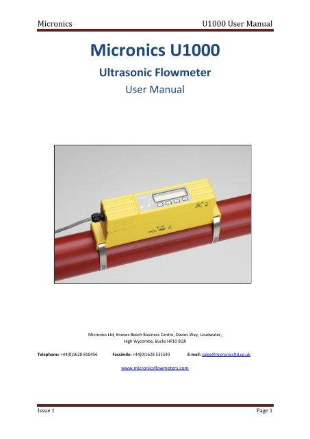
<strong>Micronics</strong><br />
<strong>U1000</strong> User <strong>Manual</strong><br />
<strong>Micronics</strong> <strong>U1000</strong><br />
Ultrasonic Flowmeter<br />
User <strong>Manual</strong><br />
<strong>Micronics</strong> <strong>Ltd</strong>, Knaves Beech Business Centre, Davies Way, Loudwater,<br />
High Wycombe, Bucks HP10 9QR<br />
Telephone: +44(0)1628 810456 Facsimile: +44(0)1628 531540 E-mail: sales@micronicsltd.co.uk<br />
www.micronicsflowmeters.com<br />
<strong>Issue</strong> 1 Page 1
<strong>Micronics</strong><br />
<strong>U1000</strong> User <strong>Manual</strong><br />
Table of Contents<br />
1 General Description ........................................................................................................................ 4<br />
2 How does it work? .......................................................................................................................... 5<br />
3 User interface .................................................................................................................................. 6<br />
3.1 Key switches ............................................................................................................................ 6<br />
4 Installing the <strong>U1000</strong> ........................................................................................................................ 6<br />
4.1 Preparation ............................................................................................................................. 7<br />
4.2 Attaching the <strong>U1000</strong> to the pipe ............................................................................................ 8<br />
4.3 <strong>U1000</strong> interface cable ............................................................................................................. 9<br />
4.4 Connecting the <strong>U1000</strong> to the Supply ...................................................................................... 9<br />
4.5 Pulse Output connection ........................................................................................................ 9<br />
4.6 Current Output ...................................................................................................................... 10<br />
4.7 Cable Screen .......................................................................................................................... 10<br />
5 Powering up for the first time ....................................................................................................... 10<br />
5.1 How to enter the Pipe ID ...................................................................................................... 10<br />
5.2 Pulse output .......................................................................................................................... 11<br />
5.2.1 Volumetric mode .......................................................................................................... 12<br />
5.2.2 Frequency mode ........................................................................................................... 12<br />
5.3 4-20mA Current output ........................................................................................................ 12<br />
6 Subsequent Power-ON Sequence ................................................................................................. 12<br />
7 Password Controlled Menus ......................................................................................................... 12<br />
7.1 General procedure for changing menu settings ................................................................... 13<br />
7.1.1 Selection menus ............................................................................................................ 13<br />
7.1.2 Data entry menus .......................................................................................................... 13<br />
7.2 User Password controlled menu structure ........................................................................... 14<br />
8 Diagnostics Menu .......................................................................................................................... 19<br />
9 Relocation of guide rail ................................................................................................................. 20<br />
10 Appendix I – <strong>U1000</strong> Specification ............................................................................................. 21<br />
11 Appendix II – Default values ..................................................................................................... 22<br />
12 Appendix III – Error and Warning Messages ............................................................................. 23<br />
12.1 System errors ........................................................................................................................ 23<br />
12.2 Errors ..................................................................................................................................... 23<br />
12.3 Warnings ............................................................................................................................... 23<br />
<strong>Issue</strong> 1 Page 2
<strong>Micronics</strong><br />
<strong>U1000</strong> User <strong>Manual</strong><br />
<strong>Issue</strong> 1 Page 3
<strong>Micronics</strong><br />
<strong>U1000</strong> User <strong>Manual</strong><br />
1 General Description<br />
The <strong>U1000</strong> is a fixed installation, clamp-on flowmeter that is easy to install and requires the<br />
minimum of information to be entered by the user. Unlike other clamp-on flowmeters, the<br />
<strong>U1000</strong> transducer separation distance is factory preset to the internal diameter (ID) of the<br />
application pipe. Both the electronics and guide rail housings form an integral unit that is<br />
attached to the pipe using the supplied jubilee clips. Power to the unit is provided by an<br />
external 12 - 24V ac/dc power supply. The <strong>U1000</strong> is intended to operate on steel pipes with<br />
ID’s in the range 48mm (2”) to 164mm (6”).<br />
Compact, rugged and reliable, the <strong>U1000</strong> has been designed to provide sustained<br />
performance in industrial environments.<br />
<strong>U1000</strong> standard features include:<br />
• 2 line x 16 character LCD with backlight<br />
• 4-key keypad<br />
• Isolated pulse output<br />
• 4-20mA current output<br />
• Simplified factory configured guide rail and transducer assembly<br />
• Continuous signal monitoring<br />
• Password protected menu operation for secure use<br />
• Operates from external 12 to 24Vac or dc power supplies<br />
Typical applications<br />
• Hot water metering and flow measurement<br />
• Flow measurement for Heat Metering<br />
• Chilled water metering and flow measurement<br />
• Potable water metering and flow measurement<br />
• Process water metering and flow<br />
• Ultra pure water measurement.<br />
<strong>Issue</strong> 1 Page 4
<strong>Micronics</strong><br />
<strong>U1000</strong> User <strong>Manual</strong><br />
2 How does it work?<br />
The <strong>U1000</strong> is a clamp-on, ultrasonic flowmeter that uses a multiple slope transit time<br />
algorithm to provide accurate flow measurements.<br />
Figure 1 Principle of Transit-Time operation<br />
An ultrasonic beam of a given frequency is generated by applying a repetitive voltage pulse<br />
to the transducer crystals. This transmission goes first from the Downstream transducer to<br />
the Upstream transducer (red) as shown in the upper half of Fig. 1. The transmission is then<br />
made in the reverse direction, being sent from the Upstream transducer (red) to the<br />
Downstream transducer (blue) as shown in the lower half of Fig.1. The speed at which the<br />
ultrasound is transmitted through the liquid is accelerated slightly by the velocity of the liquid<br />
through the pipe. The subsequent time difference T1 – T2 is directly proportional to the liquid<br />
flow velocity.<br />
<strong>Issue</strong> 1 Page 5
<strong>Micronics</strong><br />
<strong>U1000</strong> User <strong>Manual</strong><br />
3 User interface<br />
Figure 2 illustrates the <strong>U1000</strong> user interface comprising:-<br />
One 2 line x 16 character LCD with backlight<br />
Four tactile key switches<br />
Two LED’s<br />
3.1 Key switches<br />
Figure 2 <strong>U1000</strong> User Interface<br />
><br />
V<br />
Λ<br />
<br />
Selection key. Allows the user to select between options on the<br />
display.<br />
Used to increment the value of each digit in numeric entry fields.<br />
Used to decrement the value of each digit in numeric entry<br />
fields.<br />
Used to enter the selection displayed or terminate the data<br />
entry. Pressing this key will take the user to another menu or to<br />
the Flow Reading screen.<br />
4-20mA LED is illuminated when the 4-20mA output is ON<br />
Pulse LED is illuminated when the Pulse output is ON<br />
4 Installing the <strong>U1000</strong><br />
Air<br />
45°<br />
Guide<br />
rail<br />
Uniform Flow Profile<br />
Distorted Flow Profile<br />
Flow<br />
Possible<br />
sludge<br />
10 x Diameter<br />
Valid transducer location<br />
20 x Diameter<br />
Figure 3 Location of Transducers<br />
Flow<br />
<strong>Issue</strong> 1 Page 6
<strong>Micronics</strong><br />
<strong>U1000</strong> User <strong>Manual</strong><br />
In many applications an even flow velocity profile over a full 360° is unattainable due, for<br />
example, to the presence of air turbulence at the top of the flow and possibly sludge at the<br />
bottom of the pipe. Experience has shown that the most consistently accurate results are<br />
achieved when the transducer guide rails are mounted at 45°with respect to the top of the<br />
pipe.<br />
The <strong>U1000</strong> equipment expects a uniform flow profile, as a distorted flow will produce<br />
unpredictable measurement errors. Flow profile distortions can result from upstream<br />
disturbance such as bends, tees, valves, pumps and other similar obstructions. To ensure a<br />
uniform profile the transducers must be mounted far enough away from any cause of<br />
distortion such that it no longer has an effect.<br />
To obtain the most accurate results the condition of both the liquid and the pipe must be<br />
suitable to allow ultrasound transmission along the predetermined path. It is important that<br />
liquid flows uniformly within the length of pipe being monitored, and that the flow profile is not<br />
distorted by any upstream or downstream obstructions. This is best achieved by ensuring<br />
there is a straight length of pipe upstream of the transducers of at least 20 times the pipe<br />
diameter, and 10 times the pipe diameter on the downstream side, as shown in Figure 3.<br />
Flow Measurements can be made on shorter lengths of straight pipe, down to 10 diameters<br />
upstream and 5 diameters downstream, but when the transducers are mounted this close to<br />
any obstruction the resulting errors can be unpredictable.<br />
Key Point: Do not expect to obtain accurate results if the transducers are positioned close to<br />
any obstruction that distorts the uniformity of the flow profile.<br />
<strong>Micronics</strong> <strong>Ltd</strong> accepts no responsibility or liability if product has not been installed in<br />
accordance with the installation instructions applicable to the product.<br />
4.1 Preparation<br />
1. Before you attach the transducers you should first ensure that the proposed location<br />
satisfies the distance requirements shown in Figure 3 otherwise the resulting accuracy of the<br />
flow readings may be affected.<br />
2. Prepare the pipe by degreasing it and removing any loose material or flaking paint in order<br />
to obtain the best possible surface. A smooth contact between pipe surface and the face of<br />
the transducers is an important factor in achieving a good ultrasound signal strength and<br />
therefore maximum accuracy.<br />
<strong>Issue</strong> 1 Page 7
<strong>Micronics</strong><br />
<strong>U1000</strong> User <strong>Manual</strong><br />
4.2 Attaching the <strong>U1000</strong> to the pipe<br />
Follow the four steps shown in Figure 4 below to attach the <strong>U1000</strong> to the pipe.<br />
The grease provided in the syringe is applied to<br />
the centre of the sensors as shown above.<br />
Clamp guide rail and sensor assembly to pipe and<br />
release sensor locking screws.<br />
Connect power and sensors to the electronics<br />
assembly. Sensor leads can be connected either<br />
way round.<br />
Click electronic assembly onto guide rails and<br />
sensor assembly<br />
Figure 4 simple steps to attaching the <strong>U1000</strong> on the pipe<br />
<strong>Issue</strong> 1 Page 8
<strong>Micronics</strong><br />
<strong>U1000</strong> User <strong>Manual</strong><br />
The locking screws and washers should be kept in case it is necessary to change the location of the<br />
guide rail and sensors. See the relocation section for the procedure to do this.<br />
4.3 <strong>U1000</strong> interface cable<br />
The <strong>U1000</strong> interface cable supplied is a 6-core cable and is shown in Figure 5.<br />
Un-insulated screen<br />
Power<br />
Pulse<br />
Figure 5. <strong>U1000</strong> Interface Cable<br />
4-20mA<br />
The polarity of the wires is as follows:<br />
24V Input<br />
24V Return<br />
Pulse Output<br />
Pulse Return<br />
4-20mA Output (+)<br />
4-20mA Return (-)<br />
The un-insulated wire is the connection to the screen of the cable and should be earthed for full<br />
immunity to electrical noise.<br />
4.4 Connecting the <strong>U1000</strong> to the Supply<br />
The <strong>U1000</strong> will operate within the voltage range 12 - 24V AC/DC. Connect the external<br />
power supply to the Brown and Blue wires of the six core cable. For full compliance with<br />
EMC regulation a 12V supply is recommended for domestic and light industrial applications.<br />
4.5 Pulse Output connection<br />
The isolated pulse output is provided by a SPNO MOSFET Relay which has a maximum<br />
load current of 500mA and maximum load voltage of 48V AC. The relay also provides 2500V<br />
isolation.<br />
The pulse output is available at the White and Green wires. Electrically this is a volt free<br />
contact closure.<br />
<strong>Issue</strong> 1 Page 9
<strong>Micronics</strong><br />
<strong>U1000</strong> User <strong>Manual</strong><br />
4.6 Current Output<br />
The isolated 4-20mA is a current source and can drive into a maximum load of 620Ω.<br />
The 4-20mA current output is available at the Red and Black wires. The polarities are shown<br />
in Figure 5.<br />
The alarm current due to a flow outside the range specified or due to a loss of signal is set at<br />
3.5mA.<br />
4.7 Cable Screen<br />
For full immunity to electrical interference the screen of the cable should be connected to<br />
Earth.<br />
5 Powering up for the first time<br />
Powering up for the first time will initiate the sequence shown in Fig.6:<br />
1. The <strong>Micronics</strong> startup screen is displayed for 5 seconds<br />
2. The user enters the pipe ID (refer to section 5.1)<br />
3. The <strong>U1000</strong> checks for a valid signal<br />
Figure 6 Initial Power-on sequence<br />
4. If a valid signal is found, signal strength and flow magnitude are displayed. The direction<br />
of flow when powered up will be set as that for positive flow. The current output and pulse<br />
output will relate to the flow in this direction. If the flow is reversed then the flow rate will still<br />
be displayed but the activity indication will change from an asterisk to an exclamation mark.<br />
No pulses will be generated, and the current will go to the 3.5mA alarm state if the flow is<br />
reversed.<br />
5.1 How to enter the Pipe ID<br />
Figure 7 shows the Enter Pipe ID screen after an initial power up.<br />
<strong>Issue</strong> 1 Page 10
<strong>Micronics</strong><br />
<strong>U1000</strong> User <strong>Manual</strong><br />
Figure 7 Enter Pipe ID Screen (Metric)<br />
Initially, the hundreds unit (050.0) will blink.<br />
Press the<br />
key to increment the hundreds digit (050.0) in the sequence 0, 1. Press<br />
Λ once to increment digit, or hold key down to automatically toggle between<br />
0 and 1.<br />
Press the<br />
Press the<br />
Press the<br />
Press the<br />
Press the<br />
V<br />
><br />
><br />
><br />
<br />
key to decrement the hundreds digit in the sequence 1, 0. Press once to<br />
decrement digit, or hold key down to automatically toggle between 1 and<br />
0.<br />
key to move to the tens digit (050.0). The tens digit should now blink.<br />
Increment the tens digit in the sequence 0,1,2,3,4,5,6,7,8,9,0 using the<br />
key. Press once to increment digit or hold down to scroll through<br />
the numeric sequence. Decrement the tens digit in the sequence<br />
9,8,7,6,5,4,3,2,1,0,9 using the key. Press once to increment digit<br />
or hold down to scroll through the numeric sequence.<br />
key to move to the units digit (050.0). The units digit should now blink.<br />
Increment or decrement the units digit in an identical manner to the tens<br />
digit described above.<br />
key to move to the decimal digit (050.0). The decimal digit should now<br />
blink. Increment or decrement the decimal digit in an identical manner to<br />
the tens digit described above.<br />
key to enter the Pipe ID numerical value.<br />
V<br />
If any of the parameters need to be changed from the default values, for example different<br />
units are required, then the menu system must be activated via the password (see section<br />
7).<br />
5.2 Pulse output<br />
Pulse output can be set up to operate in two modes, namely volumetric and frequency.<br />
<strong>Issue</strong> 1 Page 11
<strong>Micronics</strong><br />
<strong>U1000</strong> User <strong>Manual</strong><br />
5.2.1 Volumetric mode<br />
In Volumetric mode, each pulse output represents a measured volume of 10 litres (default<br />
value). In Volumetric mode, with the Vol per Pulse set to 1 and the pulse width set to 25ms,<br />
the maximum number of pulses that can be output (without storage) is 1/(0.025*2) = 20<br />
pulses per second. If the flow rate in the pipe is such that more than 20 pulses per second<br />
are generated, a Pulse Overflow error may eventually occur if the stored number of pulses<br />
exceeds 1000. To avoid this, set the Vol per Pulse to 10 litres.<br />
5.2.2 Frequency mode<br />
In Frequency mode, the pulse output frequency is proportional to the flow rate within a<br />
specified frequency range of 0 – 200Hz.<br />
5.3 4-20mA Current output<br />
The default 4-20mA output setting will be ON, and the 4-20mA LED on the keypad will be<br />
illuminated. The default flow for 20mA output will be automatically set depending on the pipe<br />
size. The default flow for 4mA is 0. This can be changed, see section 7.<br />
If the flow reading is greater than that set as the 20mA value, or there is negative, flow, or no<br />
flow signal can be detected, then an alarm current of 3.5mA will generated.<br />
Note: The 4-20mA current output is factory calibrated.<br />
6 Subsequent Power-ON Sequence<br />
If the power supply is cycled OFF then ON after the pipe ID has been entered, all<br />
subsequent start-ups will use the same configuration as was previously entered. If the<br />
configuration needs to be changed for any reason, the user can make use of the passwordcontrolled<br />
menu as described in section 7.<br />
7 Password Controlled Menus<br />
The password controlled menu allows the user some flexibility to change the default settings:<br />
User Password (71360):<br />
Change the dimensions from mm to inches or vice-versa.<br />
Change from Flow to Velocity Measurement<br />
Change the system units litres/m 3 or Impgal/USgal<br />
Change the flow units l/s, l/min or gal/s, gal/min or USgals/s, USgals/min<br />
Change the default value for Flow at Maximum Current<br />
Change the default setting for Flow at Minimum Current<br />
Change the Pulse Output type<br />
Change the Pulse output parameters<br />
<strong>Issue</strong> 1 Page 12
<strong>Micronics</strong><br />
<strong>U1000</strong> User <strong>Manual</strong><br />
7.1 General procedure for changing menu settings<br />
7.1.1 Selection menus<br />
When a password controlled menu is selected the procedure for changing the default setting<br />
is the same for all menus. For example, consider the Flow Units menu shown in Figure 8.<br />
Flow Units:<br />
l/min | l/s<br />
Figure 8 Flow Units menu<br />
The default value ‘l/min’ will blink to indicate that this is the current setting. To change to ‘l/s’,<br />
press the<br />
Press the<br />
><br />
<br />
key. Now the ‘l/s’ units will blink to indicate that this is now the selected units.<br />
key to confirm the change.<br />
7.1.2 Data entry menus<br />
Menus containing a numeric value can be altered using the following procedure. For<br />
example, consider changing the Flow at maximum current from the default setting 1000 litres<br />
as indicated in Figure 9. to 1258 litres.<br />
Flow @ 20mA:<br />
1000.0<br />
Figure 9 Example of a Data entry screen<br />
Press the<br />
><br />
key twice to select the hundreds unit (1000.0) which will now blink<br />
Press the Press the key twice to increment the hundreds unit from 0 to 2<br />
Λ (1200.0)<br />
Press the<br />
><br />
key once to select the tens unit (1200.0) which will now blink<br />
Press the key five times to increment the hundreds unit from 0 to 5 (1250.0)<br />
Press the<br />
Λ<br />
><br />
key once to select units (1250.0) which will now blink<br />
Press the V key twice to decrement the units from 0 to 8 (1258.0)<br />
<strong>Issue</strong> 1 Page 13
<strong>Micronics</strong><br />
<strong>U1000</strong> User <strong>Manual</strong><br />
Press the<br />
<br />
key to confirm the change<br />
All numeric data menus can be changed in this way.<br />
7.2 User Password controlled menu structure<br />
Ensure that the instrument is in Flow Reading mode then press the key to go to the<br />
user password menu. Enter 71360 using the procedure explained in section 7.1.2. to enter<br />
the password.<br />
The flow chart shown in Fig.9 shows the user password menu structure. To skip over any<br />
menu item that should remain unchanged, simply press the<br />
<br />
key.<br />
<strong>Issue</strong> 1 Page 14
<strong>Micronics</strong><br />
<strong>U1000</strong> User <strong>Manual</strong><br />
71360 MENU<br />
Sig: 87% *<br />
246.3 l/min<br />
Invalid & OR No<br />
input for 10 seconds<br />
Enter Password:<br />
*****<br />
ERROR:<br />
Invalid Password<br />
User Menu:<br />
Setup<br />
User Menu:<br />
Pulse Output<br />
User Menu:<br />
Current Output<br />
v<br />
v<br />
<br />
<br />
<br />
Setup Menu<br />
Pulse Output Menu<br />
Current Output Menu<br />
User Menu:<br />
Calibration<br />
User Menu:<br />
Totaliser<br />
v<br />
v<br />
<br />
<br />
Calibration Menu<br />
Totaliser Menu<br />
User Menu:<br />
Exit<br />
Checking Signals<br />
******<br />
v<br />
<br />
Sig: 87% *<br />
246.3 l/min<br />
<strong>Issue</strong> 1 Page 15
<strong>Micronics</strong><br />
<strong>U1000</strong> User <strong>Manual</strong><br />
SETUP MENU<br />
Range 1.90 – 6.50<br />
2.000 inches<br />
Select Dimensions:<br />
mm | inches<br />
Inches & <br />
Invalid<br />
& <br />
mm & <br />
Range 48 – 164mm<br />
050.0 mm<br />
Invalid &<br />
<br />
Enter Pipe ID:<br />
050.0 mm<br />
Enter Pipe ID:<br />
2.000 inches<br />
Vel & (m/s)<br />
Valid & <br />
Valid & <br />
Select Reading:<br />
Flow | Vel<br />
Valid & <br />
Select Reading:<br />
Flow | Vel<br />
Flow & <br />
Flow & <br />
m3 & <br />
System Units:<br />
litres | m3<br />
System Units:<br />
Impgal | USgal<br />
Litres & <br />
Vel & <br />
(ft/s)<br />
Impgal & <br />
Flow Units<br />
m3/min | m3/hr<br />
Flow Units<br />
l/min | l/s<br />
Flow Units<br />
gal/min | gal/hr<br />
<br />
<br />
<br />
USgal & <br />
Flow Units<br />
USgal/min | USgal/hr<br />
<strong>Issue</strong> 1 Page 16
<strong>Micronics</strong><br />
<strong>U1000</strong> User <strong>Manual</strong><br />
PULSE OUTPUT MENU<br />
Range 1 – 200<br />
200<br />
Select Pulse:<br />
ON | OFF<br />
On & <br />
Off & <br />
Invalid &<br />
<br />
Freq & <br />
Valid & <br />
Pulse Type:<br />
VOLUME | FREQ<br />
Max Pulse Freq:<br />
200<br />
Volume & <br />
Volume per Pulse:<br />
10.0 l<br />
Valid & <br />
Valid & <br />
Max Flow @ Freq:<br />
9999.0<br />
Valid & <br />
Pulse Width<br />
25 ms<br />
Invalid & <br />
Range 3 - 99<br />
25 ms<br />
Valid & <br />
Valid & <br />
Valid & <br />
TOTALISER MENU<br />
Select Totals<br />
ON|OFF<br />
On & <br />
Reset + Total<br />
NO |YES<br />
Off & <br />
<br />
If the Total is turned on then the display will alternate between the flow reading and the total.<br />
Either display can be held for 30seconds by pressing the<br />
><br />
key.<br />
<strong>Issue</strong> 1 Page 17
<strong>Micronics</strong><br />
<strong>U1000</strong> User <strong>Manual</strong><br />
CURRENT OUTPUT MENU<br />
Select 4-20mA:<br />
ON | OFF<br />
ON & <br />
Flow @ 20mA<br />
1000.0<br />
Valid & <br />
OFF & <br />
Flow @ 4mA<br />
0000.0<br />
Valid & <br />
CALIBRATION MENU<br />
Zero Offset:<br />
Averaging…9<br />
v To Set<br />
Done<br />
71360<br />
& <br />
Damping Time [s]:<br />
20<br />
Zero Cut-off:<br />
0.10 m/s<br />
Valid & <br />
Zero Offset<br />
0.000 l/min<br />
Calibrat. Factor:<br />
1.000<br />
<br />
<br />
Valid & <br />
Range 0.00 – 0.50<br />
0.10 m/s<br />
^ To Clear<br />
Invalid & <br />
Range 0.500–1.500<br />
1.000<br />
NO |YES<br />
Invalid & <br />
<strong>Issue</strong> 1 Page 18
<strong>Micronics</strong><br />
<strong>U1000</strong> User <strong>Manual</strong><br />
8 Diagnostics Menu<br />
The diagnostics menu provides some additional information about the flowmeter and its setup. The<br />
V<br />
menu can be accessed by pressing the key from the main flow-reading screen. The menu<br />
shown below describes the various diagnostics items.<br />
DIAGNOSTICS MENU<br />
Press<br />
To exit the Diagnostics menu<br />
Sig: 87% *<br />
246.3 l/min<br />
N. B. The key board is less responsive in the<br />
Diagnostics Menu and longer key presses are<br />
required.<br />
><br />
Est.TA 85.64<br />
Act .TA 86.77<br />
The Estimated TA (Time of Arrival) and Actual TA show the<br />
theoretical and measured transit times. These values should<br />
be within several per cent of each other.<br />
><br />
><br />
Gain 845 (x1)<br />
DT 125 ns<br />
<br />
The gain on line one is an indicator of the signal strength. A<br />
good signal should have a gain of between 600 to 970. The<br />
number in parentheses is the switch setting and should be x1.<br />
The second line shows the current time differential between<br />
the upstream and downstream signals.<br />
><br />
Rev: 05.00.001<br />
S/N: 12547<br />
The unit’s software version is shown on line 1.<br />
Line 2 shows the unit’s serial number.<br />
><br />
Pulse Frequency<br />
124<br />
If the Frequency pulse option is enabled this screen displays<br />
the current pulse output frequency. This is proportional to<br />
the flow rate.<br />
PCB Temperature<br />
34<br />
The temperature of the PCB should not exceed 65°C.<br />
<strong>Issue</strong> 1 Page 19
<strong>Micronics</strong><br />
<strong>U1000</strong> User <strong>Manual</strong><br />
9 Relocation of guide rail<br />
If it is necessary to relocated the guide rail and sensor assembly use the following procedure<br />
1. Remove complete assembly from the pipe<br />
2. Use a screwdriver to unlatch the plastic clips that hold the electronics on to the Guide<br />
rail.<br />
3. Disconnect the sensors<br />
4. Remove the original grease from the sensors<br />
5. Push the sensor blocks into the guide rail so that the washers and locking screws<br />
can be refitted.<br />
6. Place a bead of grease down the centre of the sensor block using the syringe<br />
provided. See illustration on fitting the guide rail to the pipe for recommended bead<br />
size.<br />
7. Follow the original procedure for installing the guide rail on the pipe.<br />
<strong>Issue</strong> 1 Page 20
<strong>Micronics</strong><br />
<strong>U1000</strong> User <strong>Manual</strong><br />
10 Appendix I – <strong>U1000</strong> Specification<br />
Table 1 lists the <strong>U1000</strong> Product Specification.<br />
General<br />
Measuring Technique<br />
Transit time<br />
Measurement channels 1<br />
Timing Resolution<br />
±50ps<br />
Turn down ratio 200:1<br />
Flow velocity range<br />
Applicable Fluid types<br />
Accuracy<br />
Repeatability<br />
0.1 to 10m/s bidirectional<br />
Clean water with < 3% by volume of particulate content.<br />
±3% of flow reading for flow rate >0.3m/s<br />
±0.5% of measured value<br />
Selectable units Velocity: m/s, ft/s<br />
Flow Rate: l/s, l/min, gal/s, gal/min, USgal/s, USgal/min,<br />
m 3 /min, m 3 /hr<br />
Volume: litres, m3, gals, USgals<br />
Languages supported<br />
English only<br />
Power input<br />
Power consomption<br />
Cable<br />
Pulse Output<br />
Output<br />
Isolation<br />
Pulse width<br />
Pulse repetition rate<br />
Frequency mode<br />
Maximum load voltage/current<br />
Current Output<br />
Output<br />
Resolution<br />
Maximum load<br />
Isolation<br />
Alarm current<br />
Enclosure<br />
Material<br />
Fixing<br />
Degree of Protection<br />
12 – 24V ac or dc<br />
7VA maximum<br />
5m screened 6 core<br />
Opto-isolated MOSFET volt free normally open contact.<br />
2500V<br />
Default value 25ms; programmable range 3 – 99ms<br />
Up to 166 pulses/sec (depending on pulse width)<br />
200 Hz maximum<br />
48V AC / 500mA<br />
4 – 20mA<br />
0.1% of full scale<br />
620Ω<br />
1500V opto-isolated<br />
3.5mA<br />
Plastic Polycarbonate<br />
Pipe mountable<br />
IP54<br />
Flammability Rating UL94 V-0<br />
Dimensions<br />
250mm x 48mm x 90mm (electronics + guide rail)<br />
Weight<br />
0.5kg<br />
Environmental<br />
Pipe temperature 0°C to 85°C<br />
Operating temperature (Electronics) 0°C to 50°C<br />
Storage temperature -10°C to 60°C<br />
Humidity<br />
90% RH at 50°C Max<br />
Display<br />
<strong>Issue</strong> 1 Page 21
<strong>Micronics</strong><br />
<strong>U1000</strong> User <strong>Manual</strong><br />
LCD<br />
2 line x 16 characters<br />
Viewing angle Min 30°, Max 40°<br />
Active area<br />
83mm (W) x 18.6mm(H)<br />
Keypad<br />
Format<br />
4 key tactile feedback membrane keypad<br />
11 Appendix II – Default values<br />
The settings will be configured at the factory for either metric or imperial units. Table 2 lists<br />
the metric default values.<br />
Table 2 System Default Values<br />
Parameter<br />
Dimensions<br />
Flow Rate<br />
Pipe size<br />
4-20mA<br />
Flow at Max Current<br />
Flow at Min Current 0<br />
Pulse Output<br />
Volume per Pulse<br />
Pulse Width<br />
Damping<br />
mm<br />
l/min<br />
Default Value<br />
50 (mm)<br />
On, 4-20mA selected<br />
Equivalent to 2m/s<br />
On<br />
10 litres<br />
25ms<br />
20 seconds<br />
Calibration Factor 1.000<br />
Zero Cut-off 0.10m/s<br />
Zero Offset<br />
0.000l/min<br />
Table 3 lists the default values when Imperial dimensions are selected.<br />
Table 3 System Default Values<br />
Parameter<br />
Dimensions<br />
Flow Rate<br />
Pipe size<br />
4-20mA<br />
Flow at Max Current<br />
Flow at Min Current 0<br />
Pulse Output<br />
Volume per Pulse<br />
Pulse Width<br />
Damping<br />
Default Value<br />
inches<br />
USgal/min<br />
2 (inches)<br />
On, 4-20mA selected<br />
Equivalent to 2m/s<br />
On<br />
10 US gallons<br />
25ms<br />
20 seconds<br />
Calibration Factor 1.000<br />
Zero Cut-off 0.10m/s<br />
Zero Offset<br />
0.000gal/min<br />
<strong>Issue</strong> 1 Page 22
<strong>Micronics</strong><br />
<strong>U1000</strong> User <strong>Manual</strong><br />
12 Appendix III – Error and Warning Messages<br />
12.1 System errors<br />
There are three possible ‘System Error’ messages that can be displayed. These are:<br />
1. Poor Signal. The unit is unable to detect a signal from one or both transducers. If<br />
this message persists the sensors will need to be relocated.<br />
2. Pulse Overflow. The value for the ‘Vol per pulse’ is set too low. Increase the Vol per<br />
Pulse setting in the password-controlled menu.<br />
3. No BBME: This indicates a unit failure. Reset the unit by turning the power on and<br />
off. Contact your supplier if the problem persists.<br />
12.2 Errors<br />
1. Invalid Password. An invalid password has been entered. The correct user password is<br />
71360.<br />
12.3 Warnings<br />
These generally advise the user that the data entered is out of the specified range.<br />
1. When an invalid Pipe ID is entered, the warning message shown below is displayed,<br />
prompting the user to enter a value between 48 and 164mm.<br />
Range 48 – 164mm<br />
0.000 mm<br />
2. When the 4-20mA current output is turned ON, the Flow at Maximum and Minimum<br />
current can be changed under password control. The valid range is 0 – 99999.0 If an invalid<br />
value is entered the following warning message is displayed:<br />
Range 0 - 99999<br />
0000.0<br />
3 When programming a Frequency Pulse output the frequency is limited to the range 1 to<br />
200 Hz. If an invalid value is entered then the following warning message is displayed.<br />
Range 1 - 200<br />
200<br />
4 When programming a Volume Pulse output the pulse width is limited to the range 2 to<br />
99ms. If an invalid value is entered then the following warning message is displayed.<br />
Range 2 - 99<br />
0000.0<br />
<strong>Issue</strong> 1 Page 23
<strong>Micronics</strong><br />
<strong>U1000</strong> User <strong>Manual</strong><br />
5 when programming the Zero Cut-off this is limited to the range 0.000 to 0.500. If an invalid<br />
value is entered then the following warning message is displayed.<br />
Range 0.00 – 0.500<br />
0000.0<br />
6 when programming the Calibration Factor this is limited to the range 0.5 to 1.5. If an invalid<br />
value is entered then the following warning message is displayed.<br />
Range 0.500 – 1.500<br />
0000.0<br />
<strong>Issue</strong> 1 Page 24