Crystal - cs5336.pdf
Crystal - cs5336.pdf
Crystal - cs5336.pdf

Create successful ePaper yourself
Turn your PDF publications into a flip-book with our unique Google optimized e-Paper software.
Semiconductor Corporation<br />
16-Bit, Stereo A/D Converters for Digital Audio<br />
Features<br />
• Complete CMOS Stereo A/D System<br />
Delta-Sigma A/D Converters<br />
Digital Anti-Alias Filtering<br />
S/H Circuitry and Voltage Reference<br />
• Adjustable System Sampling Rates<br />
including 32kHz, 44.1 kHz & 48kHz<br />
• Low Noise and Distortion<br />
>90 dB S/(N+D)<br />
• Internal 64X Oversampling<br />
• Linear Phase Digital Anti-Alias Filtering<br />
0.01dB Passband Ripple<br />
80dB Stopband Rejection<br />
• Low Power Dissipation: 400 mW<br />
Power-Down Mode for Portable<br />
Applications<br />
• Evaluation Board Available<br />
CS5336 CS5338 CS5339<br />
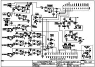
General Description<br />
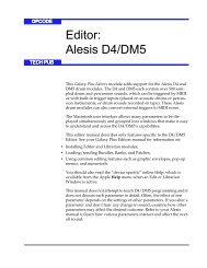
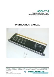
The CS5336, CS5338 & CS5339 are complete analogto-digital<br />
converters for stereo digital audio systems.<br />
They perform sampling, analog-to-digital conversion and<br />
anti-aliasing filtering, generating 16-bit values for both<br />
left and right inputs in serial form. The output word rate<br />
can be up to 50 kHz per channel.<br />
The ADCs use delta-sigma modulation with 64X oversampling,<br />
followed by digital filtering and decimation,<br />
which removes the need for an external anti-alias filter.<br />
The CS5336 & CS5338 have an SCLK which clocks out<br />
data on rising edges. The CS5339 has an SCLK which<br />
clocks out data on falling edges.<br />
The CS5336 has a filter passband of dc to 22kHz. The<br />
CS5338 & CS5339 have a filter passband of dc to 24<br />
kHz. The filters have linear phase, 0.01 dB passband<br />
ripple, and >80 dB stopband rejection.<br />
The ADC’s are housed in a 0.6" wide 28-pin plastic DIP,<br />
and also in a 0.3" wide 28-pin SOIC surface mount<br />
package. Extended temperature range versions of the<br />
CS5336 are also available.<br />
ORDERING INFORMATION: See Page 3-59<br />
ICLKA<br />
APD<br />
ACAL<br />
OCLKD<br />
ICLKD<br />
FSYNC<br />
SCLK<br />
L/R<br />
VREF<br />
AINL<br />
ZEROL<br />
28<br />
2<br />
3<br />
23 6<br />
Voltage Reference<br />
LP Filter<br />
S/H<br />
DAC<br />
7<br />
Comparator<br />
21<br />
20<br />
17<br />
Serial Output Interface<br />
Digital Decimation<br />
Filter<br />
15<br />
14<br />
16<br />
12<br />
13<br />
11<br />
SDATA<br />
CMODE<br />
SMODE<br />
TST<br />
AINR<br />
ZEROR<br />
27<br />
26<br />
LP Filter<br />
Digital Decimation<br />
Filter<br />
AGND<br />
1<br />
S/H<br />
DAC<br />
Comparator<br />
Calibration<br />
Microcontroller<br />
Calibration<br />
SRAM<br />
8<br />
22<br />
NC<br />
NC<br />
4<br />
5<br />
25<br />
24<br />
9<br />
10<br />
18<br />
19<br />
VA+<br />
VA-<br />
VL+<br />
LGND<br />
DCAL<br />
DPD<br />
VD+<br />
DGND<br />
<strong>Crystal</strong> Semiconductor Corporation<br />
P.O. Box 17847, Austin, TX 78760<br />
(512) 445-7222 FAX: (512) 445-7581<br />
AUG ’93<br />
DS23F1<br />
3-39
CS5336, CS5338, CS5339<br />
ANALOG CHARACTERISTICS (Logic 0 = GND; Logic 1 = VD+; K grade: TA = 25°C; B and T<br />
grades: TA = TMIN to TMAX; VA+, VL+,VD+ = 5V; VA- = -5V; Full-Scale Input Sinewave, 1kHz; Output word<br />
rate = 48 kHz; SCLK = 3.072 MHz; Source Impedance = 50Ω with 10 nF to AGND; Measurement Bandwidth is<br />
10 Hz to 20 kHz; unless otherwise specified.)<br />
CS5336,8,9-K CS5336-B CS5336-T<br />
Parameter Symbol Min Typ Max Min Typ Max Min Typ Max Units<br />
Specified Temperature Range TA 0 to 70 -40 to +85 -55 to +125 °C<br />
Resolution 16 - - 16 - - 16 - - Bits<br />
Dynamic Performance<br />
Dynamic Range 92.7 95.7 - 90 93.5 - 84 92 - dB<br />
Signal-to-(Noise + Distortion); THD+N S/(N+D) 90.7 92.7 - 85 89 - 82 86 - dB<br />
Signal to Peak Noise - 96 - - 95 - - 94 - dB<br />
Total Harmonic Distortion THD .0025 .001 - .005 .001 - .013 .005 - %<br />
Interchannel Phase Deviation - .0001 - - .0001 - - .0001 - °<br />
Interchannel Isolation (dc to 20 kHz) 100 106 - 90 106 - 83 96 - dB<br />
dc Accuracy<br />
Interchannel Gain Mismatch - 0.01 0.05 - .01 .05 - .01 0.1 dB<br />
Gain Error (includes Vref tolerance) - ±1 ±5 - ±2 ±5 - ±3 ±6 %<br />
Gain Drift (includes Vref drift, Note 1) - 25 - - 70 - - 70 - ppm/°C<br />
Bipolar Offset Error (Note 2) - ±5 ±15 - ±10 ±30 - ±16 ±65 LSB<br />
Offset Drift (Note1) - 15 - - 20 - - 20 - ppm/°C<br />
Analog Input<br />
Input Voltage Range (±Full Scale) VIN ±3.5 ±3.68 - ±-3.5 ±3.68 - ±3.5 ±3.68 - V<br />
Input Impedance ZIN - 65 - - 65 - - 65 - kΩ<br />
Power Supplies<br />
Power Supply Current (VA+)+(VL+) IA+ - 25 35 - 25 35 - 25 35 mA<br />
with APD, DPD low VA- IA- - -25 -35 - -25 -35 - -25 -35 mA<br />
(Normal Operation) VD+ ID+ - 30 45 - 30 45 - 30 50 mA<br />
Power Supply Current (VA+)+(VL+) IA+ - 10 50 - 10 50 - 10 50 µA<br />
with APD, DPD high VA- IA- - -10 -50 - -10 -50 - -10 -50 µA<br />
(Power-Down Mode) VD+ ID+ - 10 400 - 10 400 - 10 400 µA<br />
Power Consumption (APD, DPD Low) PDN - 400 575 - 400 575 - 400 600 mW<br />
(APD, DPD High) PDS - 0.15 2.5 - 0.15 2.5 - 0.15 2.5 mW<br />
Power Supply<br />
(dc to 26 kHz)<br />
PSRR<br />
- 54 - - 54 - - 54 - dB<br />
Rejection Ratio (26 kHz to 3.046 MHz) - 100 - - 100 - - 100 - dB<br />
Notes: 1. This parameter is guaranteed by design and/or characterization.<br />
2. After calibration with DCAL connected to ACAL, and ZEROL & ZEROR terminated to AGND with an<br />
impedance matched to the AINR & AINL source impedance. Executing a calibration with ACAL tied<br />
low (See Power Down and Offset Calibration section) will yield an offset error of typically less than<br />
± 5LSB.<br />
Specifications are subject to change without notice.<br />
3-40 DS23F1
CS5336, CS5338, CS5339<br />
DIGITAL FILTER CHARACTERISTICS<br />
(TA = 25 ° C; VA+, VL+ ,VD+ = 5V ± 5%; VA- = -5V ± 5%; Output word rate of 48 kHz)<br />
Parameter<br />
Symbol Min Typ Max<br />
Passband (-3 dB)<br />
(-3 dB)<br />
(-0.01 dB)<br />
(-0.01 dB)<br />
CS5336<br />
CS5338, CS5339<br />
CS5336<br />
CS5338, CS5339<br />
0 to 22<br />
0 to 24<br />
0 to 20<br />
0 to 22<br />
Passband Ripple - - +_ 0.01 dB<br />
Stopband<br />
CS5336<br />
26 to 3046<br />
kHz<br />
CS5338, CS5339<br />
28 to 3044<br />
kHz<br />
Stopband Attenuation (Note 3)<br />
80 - -<br />
dB<br />
Group Delay (OWR = Output Word Rate) t gd<br />
- 18/OWR -<br />
s<br />
Group Delay Variation vs. Frequency t gd<br />
- - 0.0 us<br />
Notes:<br />
3. The analog modulator samples the input at 3.072MHz for an output word rate of 48 kHz. There is<br />
no rejection of input signals which are multiples of the sampling frequency (that is: there is<br />
no rejection for n x 3.072MHz ±22kHz for the CS5338 & CS5339, or n x 3.072MHz ±20.0kHz for the<br />
CS5336, where n = 0,1,2,3...).<br />
Units<br />
kHz<br />
kHz<br />
kHz<br />
kHz<br />
DIGITAL CHARACTERISTICS<br />
(TA = 25 °C; VA+, VL+ ,VD+ = 5V ± 5%; VA- = -5V ± 5%)<br />
Parameter<br />
Symbol<br />
Min<br />
Typ Max<br />
High-Level Input Voltage VIH<br />
70%VD+<br />
-<br />
-<br />
Low-Level Input Voltage<br />
VIL<br />
-<br />
- 30% VD+<br />
High-Level Output Voltage at Io = -20uA VOH<br />
4.4<br />
-<br />
-<br />
Low-Level Output Voltage at Io = 20uA<br />
V OL<br />
-<br />
-<br />
0.1<br />
Input Leakage Current<br />
Iin<br />
-<br />
1.0 -<br />
Units<br />
V<br />
V<br />
V<br />
V<br />
uA<br />
ABSOLUTE MAXIMUM RATINGS (AGND, LGND, DGND = 0V, all voltages with respect to GND)<br />
Parameter<br />
DC Power Supplies: Positive Analog<br />
Negative Analog<br />
Positive Logic<br />
Positive Digital<br />
Input Current, Any Pin Except Supplies<br />
Analog Input Voltage (AIN and ZERO pins)<br />
Digital Input Voltage<br />
Ambient Temperature (power applied)<br />
Storage Temperature<br />
Symbol<br />
VA+<br />
VA-<br />
VL+<br />
VD+<br />
I in<br />
V INA<br />
V IND<br />
T A<br />
T stg<br />
Min<br />
-0.3<br />
+0.3<br />
-0.3<br />
-0.3<br />
-<br />
(VA- )- 0.3<br />
-0.3<br />
-55<br />
-65<br />
Max<br />
(VA+) + 0.3<br />
(VA+ )+ 0.3<br />
(VD+) + 0.3<br />
WARNING: Operation at or beyond these limits may result in permanent damage to the device.<br />
Normal operation is not guaranteed at these extremes.<br />
+6.0<br />
-6.0<br />
+6.0<br />
+_ 10<br />
+125<br />
+150<br />
Units<br />
V<br />
V<br />
V<br />
V<br />
mA<br />
V<br />
V<br />
C<br />
C<br />
DS23F1 3-41
CS5336, CS5338, CS5339<br />
SWITCHING CHARACTERISTICS<br />
(TA = 25 °C; VA+, VL+, VD+ = 5V ± 5%; VA- = -5V ± 5%; Inputs: Logic 0 = 0V, Logic 1 = VD+; CL = 20 pF)<br />
Parameter Symbol Min Typ Max Unit<br />
ICLKD Period (CMODE low) (Note 6) t clkw1 78 - 3906 ns<br />
ICLKD Low (CMODE low) t clkl1 31 - - ns<br />
ICLKD High (CMODE low) t clkh1 31 - - ns<br />
ICLKD rising to OCLKD rising (CMODE low) t io1 5 - 40 ns<br />
ICLKD Period (CMODE high) t clkw2 52 - 2604 ns<br />
ICLKD Low (CMODE high) t clkl2 20 - - ns<br />
ICLKD High (CMODE high) t clkh2 20 - - ns<br />
ICLKD rising or falling to OCLKD rising (CMODE high, Note 4) t io2 5 - 45 ns<br />
ICLKD rising to L/R edge (CMODE low, MASTER mode) t ilr1 5 - 50 ns<br />
ICLKD rising to FSYNC edge (CMODE low, MASTER mode) t ifs1 5 - 50 ns<br />
ICLKD rising to SCLK edge (CMODE low, MASTER mode) t isclk1 5 - 50 ns<br />
ICLKD falling to L/R edge (CMODE high, MASTER mode) t ilr2 5 - 50 ns<br />
ICLKD falling to FSYNC edge (CMODE high, MASTER mode) t ifs2 5 - 50 ns<br />
ICLKD falling to SCLK edge (CMODE high, MASTER mode) t isclk2 5 - 50 ns<br />
SCLK rising to SDATA valid (MASTER mode, Note 5) t sdo 0 - 50 ns<br />
SCLK duty cycle (MASTER mode) 40 50 60 %<br />
SCLK rising to L/R (MASTER mode, Note 5) t mslr -20 - 20 ns<br />
SCLK rising to FSYNC (MASTER mode, Note 5) t msfs -20 - 20 ns<br />
SCLK Period (SLAVE mode) t sclkw 155 - - ns<br />
SCLK Pulse Width Low (SLAVE mode) t sclkl 60 - - ns<br />
SCLK Pulse Width High (SLAVE mode) t sclkh 60 - - ns<br />
SCLK rising to SDATA valid (SLAVE mode, Note 5) t dss - - 50 ns<br />
L/R edge to MSB valid (SLAVE mode) t lrdss - - 50 ns<br />
Falling SCLK to L/R edge delay (SLAVE mode, Note 5) t slr1 30 - - ns<br />
L/R edge to falling SCLK setup time (SLAVE mode, Note 5) t slr2 30 - - ns<br />
Falling SCLK to rising FSYNC delay (SLAVE mode, Note 5) t sfs1 30 - - ns<br />
Rising FSYNC to falling SCLK setup time (SLAVE mode, Note 5) t sfs2 30 - - ns<br />
DPD pulse width t pdw 2 x tclkw - - ns<br />
DPD rising to DCAL rising t pcr - - 50 ns<br />
DPD falling to DCAL falling (OWR = Output Word Rate) t pcf - 4096 - 1/OWR<br />
Notes: 4. ICLKD rising or falling depends on DPD to L/R timing (see Figure 2).<br />
5. SCLK is shown for CS5336, CS5338. SCLK is inverted for CS5339.<br />
6. Specifies minimum output word rate (OWR) of 1 kHz.<br />
3-42 DS23F1
CS5336, CS5338, CS5339<br />
t<br />
clkh<br />
t<br />
clkl<br />
t<br />
clkh2<br />
t<br />
clkl2<br />
ICLKD<br />
ICLKD<br />
t clkw1<br />
t clkw2<br />
OCLKD<br />
(CMODE low)<br />
t io1<br />
OCLKD<br />
(CMODE high)<br />
t io2<br />
L/R output<br />
(MASTER mode)<br />
L/R output<br />
(MASTER mode)<br />
t ilr1<br />
t ilr2<br />
FSYNC output<br />
(MASTER mode)<br />
t ifs1<br />
FSYNC output<br />
(MASTER mode)<br />
t ifs2<br />
SCLK output<br />
(MASTER mode)<br />
SCLK output<br />
(MASTER mode)<br />
t isclk1<br />
t isclk2<br />
ICLKD to Outputs Propagation Delays (CMODE low)<br />
ICLKD to Outputs Propagation Delays (CMODE high)<br />
SCLK output<br />
(MASTER mode)<br />
t mslr<br />
L/ R output<br />
(MASTER mode)<br />
t<br />
pdw<br />
t<br />
pcf<br />
t sdo<br />
SDATA<br />
DPD<br />
t msfs<br />
t<br />
pcr<br />
FSYNC output<br />
(MASTER mode)<br />
SCLK to SDATA, L/R & FSYNC - MASTER Mode<br />
DCAL<br />
Power Down & Calibration Timing<br />
t<br />
slr1<br />
t<br />
slr2<br />
t<br />
sclkh<br />
t<br />
sclkl<br />
SCLK input<br />
(SLAVE mode)<br />
t sclkw<br />
L/R input<br />
(SLAVE mode)<br />
t<br />
lrdss<br />
t<br />
dss<br />
SDATA<br />
MSB MSB-1 MSB-2<br />
SCLK to L/R & SDATA - SLAVE mode, FSYNC high<br />
t<br />
sfs1<br />
t<br />
sfs2<br />
SCLK input<br />
(SLAVE mode)<br />
FSYNC input<br />
(SLAVE mode)<br />
SDATA<br />
MSB MSB-1 MSB-2<br />
FSYNC to SCLK - SLAVE Mode, FSYNC Controlled.<br />
DS23F1 3-43
CS5336, CS5338, CS5339<br />
RECOMMENDED OPERATING CONDITIONS<br />
(AGND, LGND, DGND = 0V; all voltages with respect to ground)<br />
Parameter Symbol Min Typ Max Units<br />
DC Power Supplies: Positive Digital<br />
VD+<br />
4.75<br />
5.0<br />
VA+<br />
V<br />
Positive Logic<br />
VL+<br />
4.75<br />
5.0<br />
VA+<br />
V<br />
Positive Analog VA+<br />
4.75<br />
5.0<br />
5.25<br />
V<br />
_<br />
_<br />
_<br />
Negative Analog VA-<br />
4.75<br />
5.0<br />
5.25<br />
V<br />
Analog Input Voltage (Note 7)<br />
_<br />
VAIN<br />
3.68 - 3.68<br />
V<br />
Notes:<br />
7. The ADCs accept input voltages up to the analog supplies (VA+, VA-). They will produce a positive<br />
full-scale output for inputs above 3.68 V and negative full-scale output for inputs below -3.68 V. These<br />
values are subject to the gain error tolerance specification. Additional tag bits are output to indicate<br />
the amount of overdrive.<br />
Ferrite Bead<br />
+5V Analog 0.1 µF<br />
0.1 µF<br />
+<br />
1 µF 0.1 µF 51 Ω<br />
4 25 18<br />
28<br />
VA+ VL+<br />
VD+<br />
APD<br />
VREF<br />
10 µF 0.1 µF<br />
+<br />
DPD<br />
ACAL<br />
Left Analog Input<br />
DCAL<br />
2<br />
AINL<br />
CS5336<br />
51 Ω 10 nF<br />
SMODE<br />
CS5338<br />
CMODE<br />
Right Analog Input<br />
27<br />
AINR<br />
CS5339<br />
51 Ω 10 nF<br />
A/D CONVERTER<br />
SDATA<br />
+<br />
6<br />
10<br />
7<br />
9<br />
13<br />
12<br />
16<br />
1 µF<br />
+5V Digital<br />
Power Down<br />
& Calibrate<br />
Control<br />
Mode<br />
Settings<br />
Audio<br />
Data<br />
Processor<br />
-5V Analog<br />
VA+<br />
3<br />
ZEROL<br />
26<br />
ZEROR<br />
1<br />
AGND<br />
8<br />
22<br />
NC<br />
NC<br />
VA- LGND DGND<br />
5 24 19<br />
0.1 µF<br />
L/R<br />
SCLK<br />
FSYNC<br />
ICLKD<br />
OCLKD<br />
ICLKA<br />
TST<br />
11<br />
14<br />
15<br />
17<br />
20<br />
21<br />
23<br />
Timing<br />
Logic<br />
& Clock<br />
Ferrite bead may<br />
be used if VD+ is<br />
derived from VA+.<br />
If used, do not drive<br />
any other logic<br />
from VD+.<br />
An example ferrite<br />
bead is Permag<br />
VK200-2.5/52<br />
+<br />
1 µF<br />
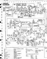
Figure 1. Typical Connection Diagram<br />
3-44 DS23F1
CS5336, CS5338, CS5339<br />
GENERAL DESCRIPTION<br />
The CS5336, CS5338, and CS5339 are 16-bit, 2-<br />
channel A/D converters designed specifically for<br />
stereo digital audio applications. The devices use<br />
two one-bit delta-sigma modulators which simultaneously<br />
sample the analog input signals at a 64<br />
X sampling rate. The resulting serial bit streams<br />
are digitally filtered, yielding pairs of 16-bit values.<br />
This technique yields nearly ideal conversion<br />
performance independent of input frequency and<br />
amplitude. The converters do not require difficultto-design<br />
or expensive anti-alias filters, and do not<br />
require external sample-and-hold amplifiers or a<br />
voltage reference.<br />
An on-chip voltage reference provides for an input<br />
signal range of ± 3.68 volts. Any zero offset is<br />
internally calibrated out during a power-up selfcalibration<br />
cycle. Output data is available in serial<br />
form, coded as 2’s complement 16-bit numbers.<br />
Typical power consumption of only 400 mW can<br />
be further reduced by use of the power-down<br />
mode.<br />
For more information on delta-sigma modulation<br />
and the particular implementation inside these<br />
ADCs, see the references at the end of this data<br />
sheet.<br />
OCLKD/<br />
L/R CMODE ICLKD ICLKA SCLK<br />
(kHz) (MHz) (MHz) (MHz)<br />
32 low 8.192 4.096 2.048<br />
32 high 12.288 4.096 2.048<br />
44.1 low 11.2896 5.6448 2.8224<br />
44.1 high 16.9344 5.6448 2.8224<br />
48 low 12.288 6.144 3.072<br />
48 high 18.432 6.144 3.072<br />
Table 1. Common Clock Frequencies<br />
SYSTEM DESIGN<br />
Very few external components are required to support<br />
the ADC. Normal power supply decoupling<br />
components, voltage reference bypass capacitors<br />
and a single resistor and capacitor on each input<br />
for anti-aliasing are all that’s required, as shown<br />
in Figure 1.<br />
Master Clock Input<br />
The master input clock (ICLKD) into the ADC<br />
runs the digital filter, and is used to generate the<br />
modulator sampling clock. ICLKD frequency is<br />
determined by the desired Output Word Rate<br />
(OWR) and the setting of the CMODE pin.<br />
CMODE high will set the required ICLKD frequency<br />
to 384 X OWR, while CMODE low will<br />
set the required ICLKD frequency to 256 X<br />
OWR. Table 1 shows some common clock frequencies.<br />
The digital output clock (OCLKD) is<br />
always equal to 128 X OWR, which is always<br />
2 X the input sample rate. OCLKD should be<br />
connected to ICLKA, which controls the input<br />
sample rate.<br />
The phase alignment between ICLKD and<br />
OCLKD is determined as follows: when CMODE is<br />
ICLKD<br />
Input<br />
DPD<br />
Input<br />
_<br />
L/ R<br />
Input<br />
OCLKD<br />
Output<br />
_<br />
L/ R<br />
Input<br />
OCLKD<br />
Output<br />
1<br />
1<br />
2<br />
2<br />
*<br />
**<br />
0 1 2 3 4 5 6 7<br />
***<br />
* DPD low is recognized on the next ICLKD rising edge (#0)<br />
** L/R rising before ICLKD rising #2 causes OCLKD -1<br />
*** L/R rising after ICLKD rising #2 causes OCLKD - 2<br />
Figure 2. ICLKD to OCLKD Timing with CMODE<br />
high (384 X OWR)<br />
DS23F1 3-45
CS5336, CS5338, CS5339<br />
L/ R<br />
Output<br />
* SCLK<br />
Output<br />
0 1 2 3 16 17 18 19 20 21 31 0 1 2 3 16 17 18 19 20 21 31 0 1<br />
FSYNC<br />
Output<br />
SDATA<br />
Output<br />
15 14 1 0 T2 T1 T0 15 14 1 0 T2 T1 T0<br />
* SCLK for CS5336/8.<br />
SCLK inverted for<br />
CS5339<br />
Left Audio Data Tag Bits Left Data Tag Right Audio Data Tag Bits Right Data Tag<br />
Figure 3. Data Output Timing - MASTER mode<br />
L/ R<br />
Input<br />
* SCLK<br />
Input<br />
0 1 2 15 16 17 18 19 20 30 31 0 1 2 15 16 17 18 19 20 21 31 0 1<br />
FSYNC<br />
Input (high)<br />
SDATA<br />
Output<br />
15 14 1 0 T2 T1 T0 15 14 1 0 T2 T1 T0<br />
* SCLK for CS5336/8.<br />
SCLK inverted for<br />
CS5339<br />
Left Audio Data Tag Bits Left Data Tag Right Audio Data Tag Bits Right Data Tag<br />
Figure 4. Data Output Timing - SLAVE Mode, FSYNC high<br />
low, ICLKD is divided by 2 to generate OCLKD.<br />
The phase relationship between ICLKD and<br />
OCLKD is always the same, and is shown in the<br />
Switching Characteristics Timing Diagrams.<br />
When CMODE is high, OCLKD is ICLKD divided<br />
by 3. There are two possible phase<br />
relationships between ICLKD and OCLKD,<br />
which depend on the start-up timing between<br />
DPD and L/R, shown in Figure 2.<br />
Serial Data Interface<br />
The serial data output interface has 3 possible<br />
modes of operation: MASTER mode, SLAVE<br />
mode with FSYNC high, and SLAVE mode with<br />
FSYNC controlled. In MASTER mode, the A/D<br />
converter is driven from a master clock (ICLKD)<br />
and outputs all other clocks, derived from ICLKD<br />
(see Figure 3). Notice the one SCLK cycle delay<br />
between L/R edges and FSYNC rising edges.<br />
FSYNC brackets the 16 data bits for each channel.<br />
In SLAVE mode, L/R and SCLK are inputs. L/R<br />
must be externally derived from ICLKD, and<br />
should be equal to the Output Word Rate. SCLK<br />
should be equal to the input sample rate, which is<br />
equal to OCLKD/2. Other SCLK frequencies are<br />
possible, but may degrade dynamic range because<br />
of interference effects. Data bits are clocked out<br />
via the SDATA pin using the SCLK and L/R inputs.<br />
The rising edge of SCLK causes the ADC to<br />
3-46 DS23F1
CS5336, CS5338, CS5339<br />
*<br />
L/ R<br />
Input<br />
SCLK<br />
Input<br />
0 1 2<br />
15 16 17 18 19 20 0 1 2 15 16 17 18 19 20<br />
FSYNC<br />
Input<br />
** *** **<br />
***<br />
SDATA<br />
Output<br />
15 15 14 1 0 T2 T1 T0 15 15 14 1 0 T2 T1 T0<br />
Left Audio Data Tag Bits Left Data Right Audio Data Tag Bits Right Data<br />
Tag<br />
Tag<br />
*<br />
SCLK for CS5336/8.<br />
**<br />
***<br />
Rising FSYNC enables<br />
SCLK inverted for CS5339<br />
SCLK to clock out SDATA<br />
Falling FSYNC stops SCLK from<br />
clocking out SDATA<br />
Figure 5. Data Output Timing - SLAVE Mode, FSYNC controlled<br />
output each bit, except the MSB, which is clocked<br />
out by the L/R edge. As shown in Figure 4, when<br />
FSYNC is high, serial data bits are clocked immediately<br />
following the L/R edge.<br />
In SLAVE mode with FSYNC controlled, as<br />
shown in Figure 5, when FSYNC is low, only the<br />
MSB is clocked out after the L/R edge. With<br />
FSYNC low, SCLK is ignored. When it is desired<br />
to start clocking out data, bring FSYNC high<br />
which enables SCLK to start clocking out data.<br />
Bringing FSYNC low will stop the data being<br />
clocked out. This feature is particularly useful to<br />
Input Level T2 T1 T0<br />
1.375 x FS 1 1 1<br />
1.250 x FS to 1.375 x FS 1 1 0<br />
1.125 x FS to 1.250 x FS 1 0 1<br />
1.000 x FS to 1.125 x FS 1 0 0<br />
-1.006dB to 0.000dB 0 1 1<br />
-3.060dB to -1.006dB 0 1 0<br />
-6.000dB to -3.060dB 0 0 1<br />
< -6.000dB 0 0 0<br />
FS = Full Scale (0dB) Input<br />
position in time the data bits onto a common serial<br />
bus.<br />
The serial nature of the output data results in the<br />
left and right data words being read at different<br />
times. However, the words within an L/R cycle<br />
represent simultaneously sampled analog inputs.<br />
In all modes, additional bits are output after the<br />
data bits: 3 tag bits and a left/right indicator. The<br />
tag bits indicate a near-to-clipping input condition<br />
for the data word to which the tag bits are attached.<br />
Table 2 shows the relationship between<br />
input level and the tag bit values. The serial bit<br />
immediately following the tag bits is 0 for the<br />
left channel, and 1 for the right channel. The remaining<br />
bits before the next L/R edge will be 1’s<br />
for the left channel and 0’s for the right channel.<br />
Normally, the tag bits are separated from the<br />
audio data by the digital signal processor. However,<br />
if the tag bits are interpreted as audio data,<br />
their position below the LSB would result as a<br />
very small dc offset.<br />
In all modes, SCLK is shown for the CS5336 and<br />
CS5338, where data bits are clocked out on rising<br />
edges. SCLK is inverted for the CS5339.<br />
Table 2. Tag Bit Definition<br />
DS23F1 3-47
CS5336, CS5338, CS5339<br />
Certain serial modes align well with various interface<br />
requirements. A CS5339 in MASTER mode,<br />
with an inverted L/R signal, generates I 2 S<br />
(Philips) compatible timing. A CS5336 in MAS-<br />
TER mode, using FSYNC, interfaces well with a<br />
Motorola DSP56000. A CS5336 in SLAVE mode<br />
emulates a CS5326 style interface, and also links<br />
up to a DSP56000 in network mode.<br />
Analog Connections<br />
The analog inputs are presented to the modulators<br />
via the AINR and AINL pins. The analog input<br />
signal range is determined by the internal voltage<br />
reference value, which is typically -3.68 volts.<br />
The input signal range therefore is typically<br />
± 3.68 volts.<br />
The ADC samples the analog inputs at<br />
3.072 MHz for a 12.288 MHz ICLKD (CMODE<br />
low). For the CS5336, the digital filter rejects all<br />
noise between 26 kHz and (3.072 MHz-26 kHz).<br />
For the CS5338 and CS5339, the digital filter rejects<br />
all noise between 28 kHz and<br />
(3.072 MHz-28 kHz). However, the filter will not<br />
reject frequencies right around 3.072 MHz (and<br />
multiples of 3.072 MHz). Most audio signals do<br />
not have significant energy at 3.072 MHz. Nevertheless,<br />
a 51 Ω resistor in series with the analog<br />
input, and a 10 nF NPO or COG capacitor to<br />
ground will attenuate any noise energy at 3.072<br />
MHz, in addition to providing the optimum<br />
source impedance for the modulators. The use of<br />
capacitors which have a large voltage coefficient<br />
(such as general purpose ceramics) should be<br />
avoided since these can degrade signal linearity. If<br />
active circuitry precedes the ADC, it is recommended<br />
that the above RC filter is placed between<br />
the active circuitry and the AINR and AINL pins.<br />
The above example frequencies scale linearly with<br />
output word rate.<br />
The on-chip voltage reference output is brought<br />
out to the VREF pin. A 10 µF electrolytic capacitor<br />
in parallel with a 0.1 µF ceramic capacitor<br />
attached to this pin eliminates the effects of high<br />
frequency noise. Note the negative value of VREF<br />
when using polarized capacitors. No load current<br />
may be taken from the VREF output pin.<br />
The analog input level used as zero during the<br />
offset calibration period (described later) is input<br />
on the ZEROL and ZEROR pins. Typically, these<br />
pins are directly attached to AGND. For the ultimate<br />
in offset nulling, networks can be attached to<br />
ZEROR and ZEROL whose impedances match<br />
the impedances present on AINL and AINR.<br />
Power-Down and Offset Calibration<br />
The ADC has a power-down mode wherein typical<br />
consumption drops to 150 µW. In addition,<br />
exiting the power-down state initiates an offset<br />
calibration procedure.<br />
APD and DPD are the analog and digital powerdown<br />
pins. When high, they place the analog and<br />
digital sections in the power-down mode. Bringing<br />
these pins low takes the part out of<br />
power-down mode. DPD going low initiates a<br />
calibration cycle. If not using the power down<br />
feature, APD should be tied to AGND. When using<br />
the power down feature, DPD and APD may<br />
be tied together if the capacitor on VREF is not<br />
Cal Period<br />
(4096 x L/R clocks)<br />
(85.33 ms @ 48kHz)<br />
DPD<br />
Filter Delay Time<br />
(~40 L/R periods)<br />
(~2 ms @ 48 kHz)<br />
Normal Operation<br />
DCAL<br />
Figure 6. Initial Calibration Cycle Timing<br />
3-48 DS23F1
CS5336, CS5338, CS5339<br />
greater than 10 µF, as stated in the "Power-Up<br />
Considerations" section.<br />
During the offset calibration cycle, the digital section<br />
of the part measures and stores the value of<br />
the calibration input of each channel in registers.<br />
The calibration input value is subtracted from all<br />
future outputs. The calibration input may be obtained<br />
from either the analog input pins (AINL<br />
and AINR) or the zero pins (ZEROL and<br />
ZEROR) depending on the state of the ACAL pin.<br />
With ACAL low, the analog input pin voltages are<br />
measured, and with ACAL high, the zero pin voltages<br />
are measured.<br />
As shown in Figure 6, the DCAL output is high<br />
during calibration, which takes 4096 L/R clock<br />
cycles. If DCAL is connected to the ACAL input,<br />
the calibration routine will measure the voltage on<br />
ZEROR and ZEROL. These should be connected<br />
directly to ground or through a network matched<br />
to that present on the analog input pins. Internal<br />
offsets of each channel will thus be measured and<br />
subsequently subtracted.<br />
Alternatively, ACAL may be permanently connected<br />
low and DCAL utilized to control a<br />
multiplexer which grounds the user’s front end.<br />
In this case, the calibration routine will measure<br />
and store not only the internal offsets but also<br />
any offsets present in the front end input circuitry.<br />
During calibration, the digital output of both<br />
channels is forced to a 2’s complement zero. Subtraction<br />
of the calibration input from conversions<br />
after calibration substantially reduces any<br />
power on click that might otherwise be experienced.<br />
A short delay of approximately 40 output<br />
words will occur following calibration for the<br />
digital filter to begin accurately tracking audio<br />
band signals.<br />
Power-up Considerations<br />
Upon initial application of power to the supply<br />
pins, the data in the calibration registers will be<br />
indeterminate. A calibration cycle should always<br />
be initiated after application of power to replace<br />
potentially large values of data in these registers<br />
with the correct values.<br />
The modulators settle very quickly (a matter of<br />
microseconds) after the analog section is powered<br />
on, either through the application of power, or by<br />
exiting the power-down mode. The voltage reference<br />
can take a much longer time to reach a final<br />
value due to the presence of large external capacitance<br />
on the VREF pin; allow approximately<br />
5 ms/µF. The calibration period is long enough to<br />
allow the reference to settle for capacitor values of<br />
up to 10 µF. If a larger capacitor is used, additional<br />
time between APD going low and DPD<br />
going low should be allowed for VREF settling<br />
before a calibration cycle is initiated.<br />
Grounding and Power Supply Decoupling<br />
As with any high resolution converter, the ADC<br />
requires careful attention to power supply and<br />
grounding arrangements if its potential performance<br />
is to be realized. Figure 1 shows the<br />
recommended power arrangements, with VA+,<br />
VA- and VL+ connected to a clean ± 5 V supply.<br />
VD+, which powers the digital filter, may be run<br />
from the system +5V logic supply, provided that<br />
it is not excessively noisy (< ± 50 mV pk-to-pk).<br />
Alternatively, VD+ may be powered from VA+ via<br />
a ferrite bead. In this case, no additional devices<br />
should be powered from VD+. Analog ground and<br />
digital ground should be connected together near<br />
to where the supplies are brought onto the printed<br />
circuit board. Decoupling capacitors should be as<br />
near to the ADC as possible, with the low value<br />
ceramic capacitor being the nearest.<br />
The printed circuit board layout should have separate<br />
analog and digital regions and ground planes,<br />
DS23F1 3-49
CS5336, CS5338, CS5339<br />
with the ADC straddling the boundary. All signals,<br />
especially clocks, should be kept away from<br />
the VREF pin in order to avoid unwanted coupling<br />
into the modulators. The VREF decoupling<br />
capacitors, particularly the 0.1 µF, must be positioned<br />
to minimize the electrical path from VREF<br />
to Pin 1 AGND and to minimize the path between<br />
VREF and the capacitors. An evaluation board is<br />
available which demonstrates the optimum layout<br />
and power supply arrangements, as well as allowing<br />
fast evaluation of the ADC.<br />
To minimize digital noise, connect the ADC digital<br />
outputs only to CMOS inputs.<br />
Synchronization of Multiple CS5336/8/9<br />
In systems where multiple ADC’s are required,<br />
care must be taken to insure that the ADC internal<br />
clocks are synchronized between converters to insure<br />
simultaneous sampling. In the absence of this<br />
synchronization, the sampling difference could be<br />
one ICLKD period which is typically 81.4 nsec<br />
for a 48 kHz sample rate.<br />
SLAVE MODE<br />
Synchronous sampling in the slave mode is<br />
achieved by connecting all DPD and APD pins to<br />
a single control signal and supplying the same<br />
ICLKD and L/R to all converters.<br />
PERFORMANCE<br />
FFT Tests<br />
For FFT based tests, a very pure sine wave is presented<br />
to the ADC, and an FFT analysis is<br />
performed on the output data. The resulting spectrum<br />
is a measure of the performance of the ADC.<br />
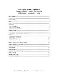
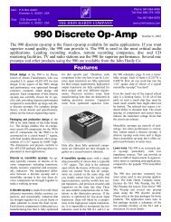
Figure 7 shows the spectral purity of the CS5336<br />
with a 1 kHz, -10 dB input. Notice the low noise<br />
floor, the absence of any harmonic distortion, and<br />
the Dynamic Range value of 95.41 dB.<br />
Figure 8 shows the CS5336 high frequency performance.<br />
The input signal is a -10 dB, 9 kHz<br />
sine wave. Notice the small 2nd harmonic at<br />
110 dB down.<br />
Figure 9 shows the low-level performance of the<br />
CS5336. Notice the lack of any distortion components.<br />
Traditional R-2R ladder based ADC’s can<br />
have problems with this test, since differential<br />
non-linearities around the zero point become very<br />
significant. Figure 10 shows the same very low<br />
input amplitude performance, but at 9kHz input<br />
frequency.<br />
MASTER MODE<br />
The internal counters of the CS5336/8/9 are reset<br />
during DPD/APD high and will start simultaneously<br />
by insuring that the release of DPD/APD<br />
for all converters is internally latched on the same<br />
rising edge of ICLKD. This can be achieved by<br />
connecting all DPD/APD pins to the same<br />
control signal and insuring that the DPD/APD<br />
falling edge occurs outside a ±30 ns window<br />
either side of an ICLKD rising edge.<br />
3-50 DS23F1
CS5336, CS5338, CS5339<br />
Signal<br />
Amplitude<br />
Relative to<br />
Full Scale<br />
(dB)<br />
0<br />
-10<br />
-20<br />
-30<br />
-40<br />
-50<br />
Output Word Rate: 48 kHz<br />
Full Scale: 7.3 Vp-p<br />
S/(N+D): 85.41 dB<br />
Dynamic Range: 95.41 dB<br />
(dc to 20 kHz)<br />
-60<br />
-70<br />
-80<br />
-90<br />
-100<br />
-110<br />
-120<br />
-130<br />
0 4 8 12 16 20 24<br />
Input Frequency (kHz)<br />
Signal<br />
Amplitude<br />
Relative to<br />
Full Scale<br />
(dB)<br />
0<br />
-10<br />
-20<br />
-30<br />
-40<br />
-50<br />
-60<br />
-70<br />
Output Word Rate: 48 kHz<br />
Full Scale: 7.3 Vp-p<br />
S/(N+D): 85.03 dB<br />
Dynamic Range: 95.033 dB<br />
(dc to 20 kHz)<br />
-80<br />
-90<br />
-100<br />
-110<br />
-120<br />
-130<br />
0 4 8 12 16 20 24<br />
Input Frequency (kHz)<br />
Figure 7. CS5336 FFT Plot with -10 dB, 1 kHz Input<br />
Figure 8. CS5336 FFT Plot with -10 dB, 9 kHz Input<br />
Signal<br />
Amplitude<br />
Relative to<br />
Full Scale<br />
(dB)<br />
0<br />
-10<br />
-20<br />
-30<br />
-40<br />
-50<br />
Output Word Rate: 48 kHz<br />
Full Scale: 7.3 Vp-p<br />
S/(N+D): 16.09 dB<br />
Dynamic Range: 96.09 dB<br />
(dc to 20 kHz)<br />
-60<br />
-70<br />
-80<br />
-90<br />
-100<br />
-110<br />
-120<br />
-130<br />
0 4 8 12 16 20 24<br />
Input Frequency (kHz)<br />
Signal<br />
Amplitude<br />
Relative to<br />
Full Scale<br />
(dB)<br />
0<br />
-10<br />
-20<br />
-30<br />
-40<br />
-50<br />
Output Word Rate: 48 kHz<br />
Full Scale: 7.3 Vp-p<br />
S/(N+D): 15.72 dB<br />
Dynamic Range: 95.72 dB<br />
(dc to 20 kHz)<br />
-60<br />
-70<br />
-80<br />
-90<br />
-100<br />
-110<br />
-120<br />
-130<br />
0 4 8 12 16 20 24<br />
Input Frequency (kHz)<br />
Figure 9. CS5336 FFT Plot with -80 dB, 1 kHz Input<br />
DNL Tests<br />
A Differential Non-Linearity test is also shown.<br />
Here, the converter is presented with a linear ramp<br />
signal. The resulting output codes are counted to<br />
yield a number which is proportional to the<br />
codewidth. A plot of codewidth versus code<br />
graphically illustrates the uniformity of the<br />
codewidths. Figure 11 shows the excellent Differential<br />
Non-Linearity of the CS5336. This plot<br />
Figure 10. CS5336 FFT Plot with -80 dB, 9 kHz Input<br />
displays the worst case positive and negative errors<br />
in each of 512 groups of 128 codes.<br />
Codewidths typically are within ± 0.2 LSB’s of<br />
ideal. A delta-sigma modulator based ADC has no<br />
inherent mechanism for generating DNL errors.<br />
The residual small deviations shown in Figure 11<br />
are a result of noise. Nevertheless, the performance<br />
shown is extremely good, and is superior to<br />
typical R-2R ladder based designs.<br />
DS23F1 3-51
CS5336, CS5338, CS5339<br />
+1<br />
+1/2<br />
DNL (LSB)<br />
-1/2<br />
0<br />
-1<br />
0 32,768<br />
65,535<br />
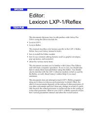
Digital Filter<br />
Figures 12 through 17 show the performance of<br />
the digital filter included in the ADC. All the plots<br />
assume an output word rate of 48 kHz. The filter<br />
frequency response will scale precisely with<br />
changes in output word rate. The passband ripple<br />
is flat to ± 0.01 dB maximum. Stopband rejection<br />
is greater than 80 dB.<br />
Figures 12,14 &16 show the CS5338 and CS5339<br />
filter characteristics. Figure 17 is an expanded<br />
view of the transition band.<br />
Figures 13,15 & 17 show the CS5336 filter characteristics.<br />
Figure 17 is an expanded view of the<br />
transition band.<br />
Codes<br />
Figure 11. CS5336 Differential Non-Linearity Plot<br />
3-52 DS23F1
CS5336, CS5338, CS5339<br />
Magnitude (dB)<br />
10<br />
0<br />
-10<br />
-20<br />
-30<br />
-40<br />
-50<br />
-60<br />
-70<br />
-80<br />
-90<br />
-100<br />
-110<br />
-120<br />
-130<br />
0 8 16 24 32 40 48<br />
Input Frequency (kHz)<br />
Magnitude (dB)<br />
10<br />
0<br />
-10<br />
-20<br />
-30<br />
-40<br />
-50<br />
-60<br />
-70<br />
-80<br />
-90<br />
-100<br />
-110<br />
-120<br />
-130<br />
0 8 16 24 32 40 48<br />
Input Frequency (kHz)<br />
Figure 12. CS5338/9 Digital Filter Stopband Rejection<br />
Figure 13. CS5336 Digital Filter Stopband Rejection<br />
0.020<br />
0.020<br />
Magnitude (dB)<br />
0.010<br />
0.000<br />
Magnitude (dB)<br />
0.010<br />
0.000<br />
-0.010<br />
-0.010<br />
-0.020<br />
0 4 8 12 16 20 24<br />
Input Frequency (kHz)<br />
-0.020<br />
0 4 8 12 16 20 24<br />
Input Frequency (kHz)<br />
Figure 14. CS5338/9 Digital Filter Passband Ripple<br />
Figure 15. CS5336 Digital Filter Passband Ripple<br />
Magnitude (dB)<br />
0<br />
-10<br />
-20<br />
-30<br />
-40<br />
-50<br />
-60<br />
-70<br />
-80<br />
-90<br />
-100<br />
22 23 24 25 26 27 28 29 30<br />
Input Frequency (kHz)<br />
Magnitude (dB)<br />
0<br />
-10<br />
-20<br />
-30<br />
-40<br />
-50<br />
-60<br />
-70<br />
-80<br />
-90<br />
-100<br />
20 21 22 23 24 25 26 27 28<br />
Input Frequency (kHz)<br />
Figure 16. CS5338/9 Digital Filter Transition Band<br />
Figure 17. CS5336 Digital Filter Transition Band<br />
DS23F1 3-53
CS5336, CS5338, CS5339<br />
PIN DESCRIPTIONS<br />
ANALOG GROUND AGND 1<br />
28 VREF VOLTAGE REFERENCE OUTPUT<br />
LEFT CHANNEL ANALOG INPUT AINL 2<br />
27 AINR RIGHT CHANNEL ANALOG INPUT<br />
LEFT CHANNEL ZERO INPUT ZEROL 3<br />
26 ZEROR RIGHT CHANNEL ZERO INPUT<br />
POSITIVE ANALOG POWER VA+ 4<br />
25 VL+ ANALOG SECTION LOGIC POWER<br />
NEGATIVE ANALOG POWER VA- 5<br />
24 LGND ANALOG SECTION LOGIC GROUND<br />
ANALOG POWER DOWN INPUT APD 6<br />
23 ICLKA ANALOG SECTION CLOCK INPUT<br />
ANALOG CALIBRATE INPUT ACAL 7<br />
22 NC NO CONNECT<br />
NO CONNECT NC 8<br />
21 OCLKD DIGITAL SECTION OUTPUT CLOCK<br />
DIGITAL CALIBRATE OUTPUT DCAL 9<br />
20 ICLKD DIGITAL SECTION CLOCK INPUT<br />
DIGITAL POWER DOWN INPUT DPD 10<br />
19 DGND DIGITAL GROUND<br />
TEST TST 11<br />
18 VD+ DIGITAL SECTION POSITIVE POWER<br />
SELECT CLOCK MODE CMODE 12<br />
17 FSYNC FRAME SYNC SIGNAL<br />
SELECT SERIAL I/O MODE SMODE 13<br />
16 SDATA SERIAL DATA OUTPUT<br />
LEFT/RIGHT SELECT L/R 14<br />
15 SCLK SERIAL DATA CLOCK<br />
Power Supply Connections<br />
VA+ - Positive Analog Power, PIN 4.<br />
Positive analog supply. Nominally +5 volts.<br />
VL+ - Positive Logic Power, PIN 25.<br />
Positive logic supply for the analog section. Nominally +5 volts.<br />
VA- - Negative Analog Power, PIN 5.<br />
Negative analog supply. Nominally -5 volts.<br />
AGND - Analog Ground, PIN 1.<br />
Analog ground reference.<br />
LGND - Logic Ground, PIN 24<br />
Ground for the logic portions of the analog section.<br />
VD+ - Positive Digital Power, PIN 18.<br />
Positive supply for the digital section. Nominally +5 volts.<br />
DGND - Digital Ground, PIN 19.<br />
Digital ground for the digital section.<br />
Analog Inputs<br />
AINL, AINR - Left and Right Channel Analog Inputs, PINS 2, 27<br />
Analog input connections for the left and right input channels. Nominally ±3.68 volts full<br />
scale.<br />
3-54 DS23F1
CS5336, CS5338, CS5339<br />
ZEROL, ZEROR - Zero Level Inputs for Left and Right Channels, PINS 3, 26.<br />
Analog zero level inputs for the left and right channels. The levels present on these pins<br />
can be used as zero during the offset calibration cycle. Normally connected to AGND,<br />
optionally through networks matched to the analog input networks.<br />
Analog Outputs<br />
VREF - Voltage Reference Output, PIN 28.<br />
Nominally -3.68 volts. Normally connected to a 0.1µF ceramic capacitor in parallel with a<br />
10µF or larger electrolytic capacitor. Note the negative output polarity.<br />
Digital Inputs<br />
ICLKA - Analog Section Input Clock, PIN 23.<br />
This clock is internally divided by 2 to set the modulators’ sample rate. Sampling rates,<br />
output rates, and digital filter characteristics scale to ICLKA frequency. ICLKA frequency<br />
is 128 X the output word rate. For example, 6.144 MHz ICLKA corresponds to an output<br />
word rate of 48 kHz per channel. Normally connected to OCLKD.<br />
ICLKD - Digital Section Input Clock, PIN 20.<br />
This is the clock which runs the digital filter. ICLKD frequency is determined by the<br />
required output word rate and by the CMODE pin. If CMODE is low, ICLKD frequency<br />
should be 256 X the desired output word rate. If CMODE is high, ICLKD should be<br />
384 X the desired output word rate. For example, with CMODE low, ICLKD should be<br />
12.288 MHz for an output word rate of 48 kHz. This clock also generates OCLKD,<br />
which is always 128 X the output word rate.<br />
APD - Analog Power Down, PIN 6.<br />
Analog section power-down command. When high, the analog circuitry is in power-down<br />
mode. APD is normally connected to DPD when using the power down feature. If power<br />
down is not used, then connect APD to AGND.<br />
DPD - Digital Power Down, PIN 10<br />
Digital section power-down command. Bringing DPD high puts the digital section into<br />
power-down mode. Upon returning low, the ADC starts an offset calibration cycle. This<br />
takes 4096 L/R periods (85.33 ms with a 12.288 MHz ICLKD). DCAL is high during the<br />
calibrate cycle and goes low upon completion. DPD is normally connected to APD when<br />
using the power down feature. A calibration cycle should always be initiated after<br />
applying power to the supply pins.<br />
ACAL - Analog Calibrate, PIN 7.<br />
Analog section calibration command. When high, causes the left and right channel<br />
modulator inputs to be internally connected to ZEROL and ZEROR inputs respectively.<br />
May be connected to DCAL.<br />
DS23F1 3-55
CS5336, CS5338, CS5339<br />
CMODE - Clock Mode Select, PIN 12.<br />
CMODE should be tied low to select an ICLKD frequency of 256 X the output word rate.<br />
CMODE should be tied high to select an ICLKD frequency of 384 X the output word<br />
rate.<br />
SMODE - Serial Interface Mode Select, PIN 13.<br />
SMODE should be tied high to select serial interface master mode, where SCLK, FSYNC<br />
and L/R are all outputs, generated by internal dividers operating from ICLKD. SMODE<br />
should be tied low to select serial interface slave mode, where SCLK, FSYNC and L/R<br />
are all inputs. In slave mode, L/R, FSYNC and SCLK need to be derived from ICLKD<br />
using external dividers.<br />
Digital Outputs<br />
SDATA - Serial Data Output, PIN 16.<br />
Audio data bits are presented MSB first, in 2’s complement format. Additional tag bits,<br />
which indicate input overload and left/right channel data, are output immediately<br />
following each audio data word.<br />
DCAL - Digital Calibrate Output, PIN 9.<br />
DCAL rises immediately upon entering the power-down state (DPD brought high). It<br />
returns low 4096 L/R periods after leaving the power down state (DPD brought low),<br />
indicating the end of the offset calibration cycle (which = 85.33 ms with a 12.288 MHz<br />
ICLKD). May be connected to ACAL.<br />
OCLKD - Digital Section Output Clock, PIN 21.<br />
OCLKD is always 128 X the output word rate. Normally connected to ICLKA.<br />
Digital Inputs or Outputs<br />
SCLK - Serial Data Clock, PIN 15.<br />
Data is clocked out on the rising edge of SCLK for the CS5336 and CS5338. Data is<br />
clocked out on the falling edge of SCLK for the CS5339.<br />
In master mode (SMODE high), SCLK is a continuous output clock at 64 X the output<br />
word rate.<br />
In slave mode (SMODE low), SCLK is an input, which requires a continuously supplied<br />
clock at any frequency from 32 X to 128 X the output word rate (64 X is preferred).<br />
When FSYNC is high, SCLK clocks out serial data, except for the MSB which appears on<br />
SDATA when L/R changes.<br />
3-56 DS23F1
CS5336, CS5338, CS5339<br />
L/R - Left/Right Select, PIN 14.<br />
In master mode (SMODE high), L/R is an output whose frequency is at the output word<br />
rate. L/R edges occur 1 SCLK cycle before FSYNC rises. When L/R is high, left channel<br />
data is on SDATA, except for the first SCLK cycle. When L/R is low, right channel data is<br />
on SDATA, except for the first SCLK cycle. The MSB data bit appears on SDATA one<br />
SCLK cycle after L/R changes.<br />
In slave mode (SMODE low), L/R is an input which selects the left or right channel for<br />
output on SDATA. The rising edge of L/R starts the MSB of the left channel data. L/R<br />
frequency must be equal to the output word rate.<br />
Although the outputs of each channel are transmitted at different times, the two words in<br />
an L/R cycle represent simultaneously sampled analog inputs.<br />
FSYNC - Frame Synchronization Signal, PIN 17.<br />
In master mode (SMODE high), FSYNC is an output which goes high coincident with the<br />
start of the first SDATA bit (MSB) and falls low immediately after the last SDATA audio<br />
data bit (LSB).<br />
In slave mode (SMODE low), FSYNC is an input which controls the clocking out of the<br />
data bits on SDATA. FSYNC is normally tied high, which causes the data bits to be<br />
clocked out immediately following L/R transitions. If it is desired to delay the data bits<br />
from the L/R edge, then FSYNC must be low during the delay period. Bringing FSYNC<br />
high will then enable the clocking out of the SDATA bits. Note that the MSB will be<br />
clocked out based on the L/R edge, independent of the state of FSYNC.<br />
Miscellaneous<br />
NC - No Connection, PINS 8, 22.<br />
These two pins are bonded out to test outputs. They must not be connected to any external<br />
component or any length of PC trace.<br />
TST -Test Input, PIN 11.<br />
Allows access to the ADC test modes, which are reserved for factory use. Must be tied to<br />
DGND.<br />
DS23F1 3-57
CS5336, CS5338, CS5339<br />
PARAMETER DEFINITIONS<br />
Resolution - The total number of possible output codes is equal to 2 N, where N = the number of bits<br />
in the output word for each channel.<br />
Dynamic Range - Full scale (RMS) signal to broadband noise ratio. The broadband noise is measured<br />
over the specified bandwidth, and with an input signal 60dB below full-scale. Units in decibels.<br />
Signal-to-(Noise plus Distortion) Ratio - The ratio of the rms value of the signal to the rms sum of all<br />
other spectral components over the specified bandwidth (typically 10 Hz to 20 kHz), including<br />
distortion components. Expressed in decibels.<br />
Total Harmonic Distortion - The ratio of the rms sum of all harmonics up to 20 kHz to the rms value<br />
of the signal. Units in percent.<br />
Interchannel Phase Deviation - The difference between the left and right channel sampling times.<br />
Interchannel Isolation - A measure of crosstalk between the left and right channels. Measured for<br />
each channel at the converter’s output with the input under test grounded and a full-scale signal<br />
applied to the other channel. Units in decibels.<br />
Interchannel Gain Mismatch - The gain difference between left and right channels. Units in<br />
decibels.<br />
Gain Error - The deviation of the measured full scale amplitude from the ideal full scale amplitude<br />
value.<br />
Gain Drift - The change in gain value with temperature. Units in ppm/°C.<br />
Bipolar Offset Error - The deviation of the mid-scale transition (111...111 to 000...000) from the ideal<br />
(1/2 LSB below AGND). Units in LSBs.<br />
3-58 DS23F1
CS5336, CS5338, CS5339<br />
REFERENCES<br />
1) "A Stereo 16-bit Delta-Sigma A/D Converter for Digital Audio" by D.R. Welland, B.P. Del Signore,<br />
E.J. Swanson, T. Tanaka, K. Hamashita, S. Hara, K. Takasuka. Paper presented at the 85th<br />
Convention of the Audio Engineering Society, November 1988.<br />
2) " The Effects of Sampling Clock Jitter on Nyquist Sampling Analog-to-Digital Converters, and on<br />
Oversampling Delta Sigma ADC’s" by Steven Harris. Paper presented at the 87th Convention of the<br />
Audio Engineering Society, October 1989.<br />
3) " An 18-Bit Dual-Channel Oversampling Delta-Sigma A/D Converter, with 19-Bit Mono Application<br />
Example" by Clif Sanchez. Paper presented at the 87th Convention of the Audio Engineering<br />
Society, October 1989.<br />
Ordering Guide<br />
Model Resolution Passband SCLK Temperature Package<br />
CS5336-KP 16-bits 22 kHz ↑ active 0°C to 70 °C 28-pin Plastic DIP<br />
CS5336-BP 16-bits 22 kHz ↑ active -40 to +85 °C 28-pin Plastic DIP<br />
CS5338-KP 16-bits 24 kHz ↑ active 0°C to 70 °C 28-pin Plastic DIP<br />
CS5339-KP 16-bits 24 kHz ↓ active 0°C to 70 °C 28-pin Plastic DIP<br />
CS5336-KS 16-bits 22 kHz ↑ active 0°C to 70 °C 28-pin SOIC<br />
CS5336-BS 16-bits 22 kHz ↑ active -40 to +85 °C 28-pin SOIC<br />
CS5338-KS 16-bits 24 kHz ↑ active 0°C to 70 °C 28-pin SOIC<br />
CS5339-KS 16-bits 24 kHz ↓ active 0°C to 70 °C 28-pin SOIC<br />
CS5336-TC 16-bits 22 kHz ↑ active -55 to +125 °C 28-pin Sidebrazed Ceramic DIP<br />
CDB5336<br />
CDB5338<br />
CDB5339<br />
CS5336 Evaluation Board<br />
CS5338 Evaluation Board<br />
CS5339 Evaluation Board<br />
DS23F1 3-59