Delta 1010 Manual - Free Pro Audio Schematics
Delta 1010 Manual - Free Pro Audio Schematics
Delta 1010 Manual - Free Pro Audio Schematics

You also want an ePaper? Increase the reach of your titles
YUMPU automatically turns print PDFs into web optimized ePapers that Google loves.
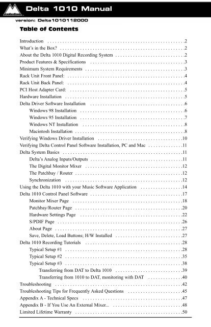
<strong>Delta</strong> <strong>1010</strong> <strong>Manual</strong><br />
version: <strong>Delta</strong><strong>1010</strong>112000<br />
Table of Contents<br />
Introduction . . . . . . . . . . . . . . . . . . . . . . . . . . . . . . . . . . . . . . . . . . . . . . . . . . . . . . .2<br />
What’s in the Box? . . . . . . . . . . . . . . . . . . . . . . . . . . . . . . . . . . . . . . . . . . . . . . . . . .2<br />
About the <strong>Delta</strong> <strong>1010</strong> Digital Recording System . . . . . . . . . . . . . . . . . . . . . . . . . . . .2<br />
<strong>Pro</strong>duct Features & Specifications . . . . . . . . . . . . . . . . . . . . . . . . . . . . . . . . . . . . . .3<br />
Minimum System Requirements . . . . . . . . . . . . . . . . . . . . . . . . . . . . . . . . . . . . . . . .3<br />
Rack Unit Front Panel: . . . . . . . . . . . . . . . . . . . . . . . . . . . . . . . . . . . . . . . . . . . . . . .4<br />
Rack Unit Back Panel: . . . . . . . . . . . . . . . . . . . . . . . . . . . . . . . . . . . . . . . . . . . . . . .4<br />
PCI Host Adapter Card: . . . . . . . . . . . . . . . . . . . . . . . . . . . . . . . . . . . . . . . . . . . . . .5<br />
Hardware Installation . . . . . . . . . . . . . . . . . . . . . . . . . . . . . . . . . . . . . . . . . . . . . . . .5<br />
<strong>Delta</strong> Driver Software Installation . . . . . . . . . . . . . . . . . . . . . . . . . . . . . . . . . . . . . .6<br />
Windows 98 Installation . . . . . . . . . . . . . . . . . . . . . . . . . . . . . . . . . . . . . . . . . .6<br />
Windows 95 Installation . . . . . . . . . . . . . . . . . . . . . . . . . . . . . . . . . . . . . . . . . .7<br />
Windows NT Installation . . . . . . . . . . . . . . . . . . . . . . . . . . . . . . . . . . . . . . . . .8<br />
Macintosh Installation . . . . . . . . . . . . . . . . . . . . . . . . . . . . . . . . . . . . . . . . . . . .8<br />
Verifying Windows Driver Installation . . . . . . . . . . . . . . . . . . . . . . . . . . . . . . . . . .10<br />
Verifying <strong>Delta</strong> Control Panel Software Installation, PC and Mac . . . . . . . . . . . . . .11<br />
<strong>Delta</strong> System Basics . . . . . . . . . . . . . . . . . . . . . . . . . . . . . . . . . . . . . . . . . . . . . . . .11<br />
<strong>Delta</strong>’s Analog Inputs/Outputs . . . . . . . . . . . . . . . . . . . . . . . . . . . . . . . . . . . . .11<br />
The Digital Monitor Mixer . . . . . . . . . . . . . . . . . . . . . . . . . . . . . . . . . . . . . . .12<br />
The Patchbay / Router . . . . . . . . . . . . . . . . . . . . . . . . . . . . . . . . . . . . . . . . . . .12<br />
Synchronization . . . . . . . . . . . . . . . . . . . . . . . . . . . . . . . . . . . . . . . . . . . . . . .12<br />
Using the <strong>Delta</strong> <strong>1010</strong> with your Music Software Application . . . . . . . . . . . . . . . . .14<br />
<strong>Delta</strong> <strong>1010</strong> Control Panel Software . . . . . . . . . . . . . . . . . . . . . . . . . . . . . . . . . . . . .17<br />
Monitor Mixer Page . . . . . . . . . . . . . . . . . . . . . . . . . . . . . . . . . . . . . . . . . . . .18<br />
Patchbay/Router Page . . . . . . . . . . . . . . . . . . . . . . . . . . . . . . . . . . . . . . . . . . .20<br />
Hardware Settings Page . . . . . . . . . . . . . . . . . . . . . . . . . . . . . . . . . . . . . . . . .22<br />
S/PDIF Page . . . . . . . . . . . . . . . . . . . . . . . . . . . . . . . . . . . . . . . . . . . . . . . . . .26<br />
About Page . . . . . . . . . . . . . . . . . . . . . . . . . . . . . . . . . . . . . . . . . . . . . . . . . . .27<br />
Save, Delete, Load Buttons; H/W Installed . . . . . . . . . . . . . . . . . . . . . . . . . . .27<br />
<strong>Delta</strong> <strong>1010</strong> Recording Tutorials . . . . . . . . . . . . . . . . . . . . . . . . . . . . . . . . . . . . . . .28<br />
Typical Setup #1 . . . . . . . . . . . . . . . . . . . . . . . . . . . . . . . . . . . . . . . . . . . . . . .28<br />
Typical Setup #2 . . . . . . . . . . . . . . . . . . . . . . . . . . . . . . . . . . . . . . . . . . . . . . .35<br />
Typical Setup #3 . . . . . . . . . . . . . . . . . . . . . . . . . . . . . . . . . . . . . . . . . . . . . . .38<br />
Transferring from DAT to <strong>Delta</strong> <strong>1010</strong> . . . . . . . . . . . . . . . . . . . . . . . . . . .39<br />
Transferring from <strong>1010</strong> to DAT, monitoring with DAT . . . . . . . . . . . . . .40<br />
Troubleshooting . . . . . . . . . . . . . . . . . . . . . . . . . . . . . . . . . . . . . . . . . . . . . . . . . . .42<br />
Troubleshooting Tips for Frequently Asked Questions . . . . . . . . . . . . . . . . . . . . . .45<br />
Appendix A - Technical Specs . . . . . . . . . . . . . . . . . . . . . . . . . . . . . . . . . . . . . . . .47<br />
Appendix B - If You Use An External Mixer... . . . . . . . . . . . . . . . . . . . . . . . . . . . .48<br />
Limited Lifetime Warranty . . . . . . . . . . . . . . . . . . . . . . . . . . . . . . . . . . . . . . . . . . .50
Introduction<br />
Congratulations on your purchase of the <strong>Delta</strong> <strong>1010</strong> Digital Recording System<br />
designed and built by M <strong>Audio</strong>. Even if you are experienced in digital recording,<br />
please take the time to read this manual. It will give you valuable information<br />
on installing your new card and the supporting software, plus help you to fully<br />
understand the function and usability of the <strong>Delta</strong> <strong>1010</strong>. Once you’re up and<br />
running, you will quickly discover the power and brilliance, both in sound and<br />
design, of your <strong>Delta</strong> <strong>1010</strong> Digital Recording System.<br />
What’s in the Box?<br />
Your <strong>Delta</strong> <strong>1010</strong> box contains:<br />
• This instruction manual.<br />
• The <strong>Delta</strong> <strong>1010</strong> rack-mount converter unit.<br />
• The <strong>Delta</strong> <strong>1010</strong> PCI host adapter card.<br />
• 25-pin D-sub to 25-pin D-sub host cable.<br />
• 9V AC 3A ‘Desktop’ power supply unit.<br />
• CD containing drivers & <strong>Delta</strong> Control Panel software for Windows<br />
98/95/NT and Macintosh OS 8.5.1 or higher.<br />
• Warranty Registration card.<br />
About the <strong>Delta</strong> <strong>1010</strong> Digital Recording<br />
System<br />
The <strong>Delta</strong> <strong>1010</strong> functions as a 10-input, 10-output digital recording interface.<br />
Eight balanced/unbalanced analog inputs and outputs plus coaxial S/PDIF I/O<br />
give you the highest quality digital I/O available -- all up to 24-bit data width and<br />
any sampling rate from 8kHz to 96kHz. Connect a line-level signal from your<br />
instrument, mixer, or pre-amp to the <strong>Delta</strong> <strong>1010</strong>’s TRS jacks on the rear of the<br />
rack-mount unit. Match the operating line level of your inputs and outputs using<br />
the individual +4/-10 switches. Record a digital audio signal from your DAT,<br />
MiniDisc, CD, or external A/D converter via the <strong>Delta</strong> <strong>1010</strong>’s S/PDIF input<br />
located on the PCI Host card. Control all routing and hardware settings with the<br />
<strong>Delta</strong>’s comprehensive control panel software.<br />
The sturdy rack-mount unit houses all of the A/D and D/A converters, keeping<br />
them away from the internal noise of your computer and assuring the best audio<br />
performance possible. Also located on the rack unit is Word Clock I/O, offering<br />
stable digital audio synchronization between the <strong>Delta</strong> <strong>1010</strong> and another word<br />
clock capable device. MIDI I/O is there too, giving you the ability to lock to<br />
MTC sync or just provide an additional MIDI port for your MIDI gear.<br />
2
Within the <strong>Delta</strong> <strong>1010</strong>’s PCI chip is a hardware digital mixer. Controlled by the<br />
included <strong>Delta</strong> Control Panel software, it may handle all of your routing needs,<br />
give you extra control of all left, right and stereo levels, in addition to control of<br />
pans, solos, and mutes.<br />
<strong>Pro</strong>duct Features & Specifications<br />
• 10x10 24-bit/96khz full-duplex recording interface.<br />
• PCI host card with external rack-mounted converter unit.<br />
• 8x8 analog I/O, balanced or unbalanced on 1/4” TRS connectors,<br />
+4dB or -10dB operation, individually selectable on the external<br />
rack-mount unit.<br />
• MIDI and Word Clock I/O on the rack-mount unit, S/PDIF I/O on<br />
the PCI card.<br />
• High dynamic range (A-weighted measured): D/A 108dB, A/D<br />
109dB.<br />
• Low distortion (measured THD @ 0dBFS): D/A less than 0.0015%,<br />
A/D less than 0.001%.<br />
• All data paths support up to 24bit/96kHz performance, no upgrades<br />
necessary.<br />
• Comprehensive digital mixing, routing, and monitoring capabilities<br />
with included <strong>Delta</strong> Control Panel software.<br />
• Hardware sample-accurate sync will allow linking of multiple <strong>Delta</strong><br />
units.<br />
• Windows 95/98 multi-card drivers with ASIO1 and ASIO2 multicard,<br />
GSIF and EASI drivers included; Windows NT multi-card and<br />
Mac OS drivers with ASIO 1&2 also included.<br />
Minimum System Requirements<br />
Windows<br />
• Windows 95 or Windows 98.<br />
• Pentium II 300MHz for 96kHz operation. Pentium 300 MMX for<br />
48kHz or less.<br />
• 128 MB of PC100 RAM for 96kHz operation. 64MB SDRAM for<br />
48kHz or less.<br />
Mac<br />
• Mac G3 or G3 accelerator with 128 MB of RAM recommended.<br />
• Mac OS 8.5.1 minimum (8.6 recommended.)<br />
• UDMA EIDE or fast SCSI HDD recommended.<br />
3
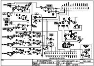
13<br />
14<br />
15<br />
2 3 4 5<br />
1<br />
6 7 8 9 10 11 12<br />
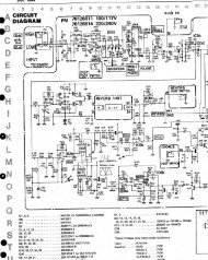
Rack Unit Front Panel:<br />
1. Power indicator LED: When lit, this LED indicates that the external rackmount<br />
unit’s power is on. Note that there is no power switch on the rackmount<br />
unit; instead the rack-mount unit’s power is enabled while the host<br />
computer is turned on.<br />
2. MIDI Input LED: This LED will light corresponding to MIDI information<br />
received at the <strong>Delta</strong> <strong>1010</strong>’s MIDI input.<br />
3. MIDI Output LED: This LED will light corresponding to MIDI information<br />
transmitted from the <strong>Delta</strong> <strong>1010</strong>’s MIDI output.<br />
4. MIDI In jack: This standard MIDI connector accepts a standard MIDI cable.<br />
Typically a MIDI controller or MTC source would be connected to the <strong>Delta</strong><br />
<strong>1010</strong> MIDI input jack.<br />
5. MIDI Out jack: This standard MIDI connector accepts a standard MIDI cable.<br />
Typically a MIDI keyboard or sound module would be connected to the MIDI<br />
output jack.<br />
Rack Unit Back Panel:<br />
6. Word Clock In: This female BNC connector is used to input word clock signals<br />
from external sources. The <strong>Delta</strong> <strong>1010</strong> is capable of synchronizing its sample<br />
rate with that of the incoming word clock signal. The input provides built-in<br />
75-ohm termination. The use of 75-ohm coaxial cables (with male BNC<br />
connectors) is highly recommended.<br />
7. Word Clock Out: This female BNC connector outputs a word clock signal that<br />
is in-sync with the present sample rate clock of the <strong>Delta</strong> <strong>1010</strong>. The output<br />
circuitry is designed to drive a word clock signal across 75-ohm coaxial cables<br />
and into a device with 75-ohm termination.<br />
8. Host Cable connector: This 25-pin D-sub connector is used to attach the<br />
external rack-mount unit to the PCI host card, using the supplied host cable.<br />
9. Analog Inputs 1-8: These jacks input analog audio from a variety of external<br />
4
sources. Each jack is 1/4” TRS (Tip-Ring-Sleeve) and is compatible with 1/4”<br />
TRS (balanced) or TS (unbalanced) connections.<br />
10. Analog Outputs 1-8: These jacks output analog audio to a variety of external<br />
sources. Each jack is 1/4” TRS (Tip-Ring-Sleeve) and is compatible with 1/4”<br />
TRS (balanced) or TS (unbalanced) connections.<br />
11. Signal-Level +4/-10 Switches: These push buttons, one per each analog input<br />
and output, set the operating signal level of each individual channel. The<br />
button in the "out" position sets the channel for a +4dB nominal signal level.<br />
Pressing the button to the "in" position sets the channel for a –10dB nominal<br />
signal level.<br />
12. Power Jack (9V AC): This connects to the included 9VAC "Desktop" power<br />
supply. It is always necessary to use a 9V AC supply, with at least 3 ampere<br />
capability. A DC power supply will never do.<br />
PCI Host Adapter Card:<br />
13. Coaxial S/PDIF Input: This RCA connector receives an S/PDIF stereo signal<br />
from your coaxial S/PDIF digital source such as a DAT, MiniDisc player or<br />
external A/D converter.<br />
14. Coaxial S/PDIF Output: This RCA connector sends an S/PDIF stereo signal to<br />
your coaxial S/PDIF digital target device such as a DAT, MiniDisc player or<br />
external D/A converter.<br />
15. Host Cable connector: This 25-pin D-sub connector attaches to the supplied<br />
host cable to allow communication between the PCI host card and the rackmount<br />
unit.<br />
Hardware Installation<br />
To mechanically install the <strong>Delta</strong> <strong>1010</strong>, do the following:<br />
1. Turn off your computer.<br />
2. Remove the computer’s cover and position the computer so that you may<br />
easily access its PCI slots.<br />
3. Select the PCI slot where you will install your <strong>Delta</strong> <strong>1010</strong> PCI host card. Make<br />
sure the slot is a PCI slot. If you don't know what "PCI slot" means, check the<br />
owner’s manual for your computer. PCI slots are distinguishable from ISA<br />
slots by being shorter and set back farther from the outside of the computer,<br />
however some newer computers have only PCI slots. Newer Macintoshs will<br />
have only PCI slots.<br />
4. Before removing the <strong>Delta</strong> <strong>1010</strong> PCI host card from its protective anti-static<br />
bag, touch the metal power s upply case of the computer in order to dissipate<br />
any static electricity your body may have accumulated. You might want to<br />
pick up a grounding wrist strap (available from electronics stores like Radio<br />
Shack) if you want to be doubly sure you aren't carrying a static charge that<br />
could damage the card.<br />
5. Remove the metal bracket that covers the access hole on the back of the<br />
computer. This bracket is usually fastened to the computer with a single<br />
screw.<br />
6. Position the <strong>Delta</strong> <strong>1010</strong> PCI host card over the target PCI slot and fit the card<br />
5
loosely over it with the card in the upright position. Press the card gently but<br />
firmly downward into the slot until the card is completely and squarely<br />
seated in the slot. If the card seems difficult to seat, a slight rocking motion<br />
may help.<br />
7. Screw the <strong>Delta</strong> <strong>1010</strong> PCI host card’s metal bracket down into the screw hole<br />
on the back of your computer using the screw you removed in step 5 above.<br />
8. Place the cover back on your computer.<br />
IMPORTANT: Complete the attachment of your <strong>Delta</strong> <strong>1010</strong> rack<br />
mount unit and its 9v power supply to the PCI card before powering<br />
up your computer. Never attach the rack unit to the PCI card while<br />
the computer is on. Doing so could damage the PCI card and void<br />
the warranty.<br />
Now it is time to connect the <strong>Delta</strong> <strong>1010</strong> rack-mount unit to the PCI host card<br />
that you have just installed. With your computer turned off:<br />
1. Mount the <strong>Delta</strong> <strong>1010</strong> rack-mount unit in your rack, or place it on a desktop<br />
in a convenient but secure place.<br />
2. Connect one end of the supplied host cable to the 25-pin D-sub connector on<br />
the rack mount unit.<br />
3. Connect the other end of the host cable to the 25-pin D-sub connector on the<br />
<strong>Delta</strong> <strong>1010</strong> PCI Host card that now resides in your computer.<br />
4. Connect the appropriate end of the 9V AC power supply into the wall outlet<br />
to supply standard house current. Plug the other end into the <strong>Delta</strong> <strong>1010</strong> 9V<br />
AC power jack.<br />
<strong>Delta</strong> Driver Software Installation<br />
The <strong>Delta</strong> <strong>1010</strong> system includes a driver CD for Windows 98/95/NT and<br />
Macintosh, containing all Windows drivers, Macintosh drivers (including all<br />
ASIO and MIDI), and <strong>Delta</strong> Control Panel software. To install these on your<br />
system, please follow these steps:<br />
Windows 98 Installation<br />
1. After installing the <strong>Delta</strong> <strong>1010</strong> hardware, boot your system and start<br />
Windows. During the Windows boot procedure, new hardware will be<br />
automatically detected by the Add New Hardware Wizard as shown here.<br />
Click ‘Next>’.<br />
6
2. The ‘Add New Hardware Wizard’ will now ask how you want to find the<br />
driver. "Search for the best driver for your device" is already selected. Click<br />
‘Next>’.<br />
3. Windows will give you a selection of locations to search. Make sure that only<br />
“Choose a Path” is checked, or click on the check box to do so. Insert the<br />
Driver CD into your CD ROM drive. Browse to your CD ROM open the <strong>Delta</strong><br />
Series folder select the corresponding opperating system (win9x). Click<br />
‘Next>’.<br />
4. The ‘Wizard’ reports that its Windows driver file search has found the M<br />
<strong>Audio</strong> <strong>Delta</strong> <strong>1010</strong>. Click Next>.<br />
5. Windows is now ready to install the driver files from the specified location.<br />
Click Next>. Windows will start to copy the files and show you a progress<br />
report screen.<br />
6. The Wizard reports that Windows has finished installing the software. Click<br />
‘Finish’. Your <strong>Delta</strong> <strong>1010</strong> is ready for action.<br />
After completion of the driver installation, Windows may require you to restart<br />
Windows. If it does request a restart, remove the Drivers CD Disk from the CD<br />
drive and respond “Yes”. The system will restart and your <strong>Delta</strong> <strong>1010</strong> is ready<br />
for play.<br />
Windows 95 Installation<br />
1. After installation of the <strong>Delta</strong> <strong>1010</strong> hardware, boot your system and start<br />
Windows. During the Windows boot procedure, new hardware will be<br />
automatically detected.<br />
2. Choose the Install of "driver from disk provided by hardware manufacturer,"<br />
then click OK.<br />
3. An ‘Install From Disk’ will prompt you to copy files from the A:\ drive. Insert<br />
the Driver software CD into your CD ROM drive. Browse to your CD ROM<br />
open the <strong>Delta</strong> Series folder select the corresponding opperating system<br />
7
(win98) (these drivers also work in Win95). Click ‘Next>’.<br />
4. Windows will start to copy files, with a progress indicator on the screen. Once<br />
this process completes itself, your <strong>Delta</strong> <strong>1010</strong> will be ready for action.<br />
After completion of the driver installation, Windows may require you to restart<br />
Windows. If it does request a restart, remove the Drivers CD Disk from the CD<br />
drive and respond “Yes”. The system will restart and your <strong>Delta</strong> <strong>1010</strong> is ready<br />
for play.<br />
Windows NT Installation<br />
1. Power up your computer after physically installing the <strong>Delta</strong> <strong>1010</strong> interface<br />
card.<br />
2. Go to Start | Settings | Control Panel and double click on ‘Multimedia.’<br />
3. Click the ‘Devices’ tab, then click the ‘Add’ button.<br />
4. “Unlisted or Updated Driver" will be highlighted at the top of the list. Click<br />
OK.<br />
5. The ‘Install Driver’ box will prompt you to insert the driver disk, and the A:<br />
prompt will appear as the path. Insert the Drivers CD into your CD ROM<br />
drive. Browse to your CD ROM open the <strong>Delta</strong> Series folder select the<br />
corresponding opperating system (winNT). Click OK.<br />
6. The "M <strong>Audio</strong> <strong>Delta</strong> Interface Card" driver will appear in the Add Unlisted or<br />
Updated Driver dialog box. Click OK.<br />
7. Windows NT will require you to restart your computer for the changes to take<br />
effect. Choose "Restart Now." Upon restart, your <strong>Delta</strong> <strong>1010</strong> will be ready for<br />
use.<br />
Macintosh Installation<br />
1. Open the System folder on your Macintosh hard drive. In the System folder,<br />
locate the Extensions folder.<br />
2. On you Drivers CD disk, open the Mac <strong>Delta</strong> Drivers folder. Place the<br />
extension file "<strong>Delta</strong> <strong>1010</strong> Driver" in your Extensions folder by clicking on it<br />
and dragging it to the Extensions folder.<br />
3. If you are using a music program that uses ASIO drivers, it will also have an<br />
ASIO folder within the application’s folder. In your Mac <strong>Delta</strong> Drivers folder<br />
you will find three <strong>Delta</strong> <strong>1010</strong> ASIO drivers. For Cubase versions 4.x, use the<br />
"ASIO2 <strong>Delta</strong><strong>1010</strong>" driver. For Metro, or earlier versions of Cubase, use the<br />
"ASIO <strong>Delta</strong><strong>1010</strong>v3" driver. For any music program that is not ASIO2 capable,<br />
use the “ASIO <strong>Delta</strong> <strong>1010</strong>” driver instead (check your program’s<br />
documentation). Place the file "ASIO <strong>Delta</strong>" in your program's ASIO folder by<br />
clicking on it and dragging it to the ASIO folder.<br />
4. Drag the "<strong>Delta</strong>Panel PPC" file onto your Macintosh hard drive. You can run<br />
the <strong>Delta</strong> Control Panel from any place that's convenient, though music<br />
software applications that use ASIO will allow you to launch the <strong>Delta</strong> panel<br />
from within the program. If not, we suggest creating an alias of the control<br />
panel by highlighting it and pressing Command (Apple key)+M. Then, drag<br />
the alias to the desktop.<br />
8
5. With the <strong>Delta</strong> <strong>1010</strong> PCI card installed, restarting the computer will load the<br />
<strong>Delta</strong> <strong>1010</strong> extension. You will be able to visually see the <strong>Delta</strong> extension icon<br />
pass by as your system loads the extensions.<br />
6. Go to the Apple menu |Control Panel | Sound. You should see the “built-in”<br />
sound icon, plus the <strong>Delta</strong> icon if your <strong>Delta</strong> <strong>1010</strong> is properly installed. If your<br />
music program does use ASIO, leave the Sound Manager driver set to "builtin"<br />
for both Sound In and Sound Out. If your program does not use ASIO<br />
(check your software’s documentation) and you will be using the Sound<br />
Manager to communicate with your <strong>Delta</strong> <strong>1010</strong>, set Sound In and Sound Out<br />
to “<strong>Delta</strong>.” See the section “Hardware Settings Page” in the <strong>Delta</strong> <strong>1010</strong><br />
“Control Panel Software” section for information on selecting Sound Manger<br />
inputs and outputs.<br />
Your <strong>Delta</strong> <strong>1010</strong> is now ready for audio input and output. To configure the <strong>Delta</strong><br />
for MIDI, you will need to have Opcode’s OMS (Open Music System) installed<br />
first. OMS is provided on the CD that came with the unit. Opening the OMS<br />
2.3.7 folder and double-clicking on the “Install OMS 2.3.7” program will install<br />
OMS in your system. To install the <strong>Delta</strong> MIDI driver once OMS is properly<br />
installed:<br />
1. Open the “<strong>Delta</strong> <strong>Pro</strong>ducts”folder on the driver CD, then the <strong>Delta</strong> <strong>1010</strong> Mac<br />
folder. Locate the “<strong>Delta</strong> OMS Driver.”<br />
2. On your Macintosh hard drive, in your System folder, you will find an “OMS<br />
Folder.”Drag the <strong>Delta</strong> OMS Driver into the OMS Folder.<br />
3. Restart your computer.<br />
To Configure your <strong>Delta</strong> <strong>1010</strong> MIDI in OMS, go to the Apple Talk Control Panel<br />
or Chooser under the Apple Menu, and make sure AppleTalk is turned off (this<br />
is recommended, although OMS will sense that it is on and prompt you to turn it<br />
off). If you are configuring OMS for the first time, follow these instructions to<br />
configure OMS.<br />
1. In the Opcode folder, which you will find on your hard drive, locate the OMS<br />
Applications folder, then “OMS Setup." Double click on OMS Setup.<br />
2. OMS will inform you that it has not yet been configured. Click OK.<br />
3. The Create A New Studio Setup dialog box now appears. Click OK.<br />
4. The "OMS Driver Search" box asks you to choose the port on which you've<br />
attached the Deta MIDI (either Modem or Printer). DO NOT choose a port,<br />
just click "Search." OMS begins Searching.<br />
5. "OMS Driver Setup" shows the "<strong>Delta</strong>" MIDI in a list when OMS successfully<br />
finds the driver. Click OK. OMS will now define (shows "Identifying") the<br />
<strong>Delta</strong> output port. The "OMS MIDI Device Setup" dialog box will appear<br />
showing the <strong>Delta</strong>'s output port with a check box to the left of the port,<br />
indicating that the port is enabled. Now click on OK.<br />
6. Next, the "My Studio Setup" appears with a 'file save' dialog box over it. You<br />
will now need to save your new Studio Setup before you can assign an<br />
instrument to the <strong>Delta</strong>'s MIDI output and input. Assign your instrument and<br />
you are done. You may now exit OMS Setup by quitting the application.<br />
9
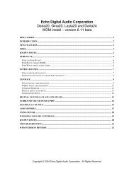
Verifying Windows Driver Installation<br />
Windows displays the <strong>Delta</strong> <strong>1010</strong> driver status in the Device Manager page of the<br />
System <strong>Pro</strong>perties dialog box. The Device Manager page is opened via the<br />
Windows Start button: select Start | Settings | Control Panel | System | Device<br />
Manager. With the Device Manager displayed, click on the "+" next to "Sound,<br />
video and game controllers" to open a list of devices, the <strong>Delta</strong> <strong>1010</strong> being a<br />
device of that nature. Below is an example view of the Device Manager..<br />
This example shows the M <strong>Audio</strong> <strong>Delta</strong> <strong>1010</strong> and Midiman WINMAN 4x4/S<br />
(another product shown here only as an example) entries in the Windows Device<br />
Manager device list. The <strong>Delta</strong> <strong>1010</strong> is properly installed with no conflicts, as is<br />
the WINMAN 4x4/S. If you do not see your M <strong>Audio</strong> <strong>Delta</strong> <strong>1010</strong> in your Device<br />
Manager in this fashion, please jump ahead to the "Troubleshooting" section of<br />
this manual.<br />
10
Verifying <strong>Delta</strong> Control Panel Software<br />
Installation, PC and Mac<br />
In Windows, open the Windows Control Panel (do so via Start | Settings | Control<br />
Panel ). If your <strong>Delta</strong> <strong>1010</strong> hardware and <strong>Delta</strong> Control Panel software are<br />
properly installed, the Windows Control Panel should display an "M <strong>Audio</strong> <strong>Delta</strong><br />
H/W" icon. By double-clicking on that icon, you can launch the <strong>Delta</strong> Control<br />
Panel software. For convenience, you may also create a shortcut on your desktop<br />
by dragging a copy of the "M <strong>Audio</strong> <strong>Delta</strong> H/W" icon from the Control Panel to<br />
your Windows desktop using your mouse or trackball. After completing the drag<br />
operation, a dialog box will ask you if you wish to create a shortcut -- click on<br />
‘Yes’. Once the shortcut is installed, all you have to do is double-click on the<br />
shortcut icon on your desktop to launch the <strong>Delta</strong> Control Panel software.<br />
On the Macintosh, the <strong>Delta</strong> Control Panel may be placed anywhere on your hard<br />
drive, or any partition of your hard drive that you find convenient. Once the<br />
control panel file has been dragged from the CD onto your hard drive, you may<br />
double click it to launch the <strong>Delta</strong> Control Panel software. You may create an<br />
alias to the control panel by highlighting it, then holding Apple key+M. This<br />
alias can then be placed on your desktop.<br />
NOTE: When using a music software program that is ASIO capable,<br />
launch the <strong>Delta</strong> Control Panel software from within that program.<br />
Some of the control panel functions will be controlled from within<br />
that program, such as master clock setting and sample rate, so it<br />
is desireable to launch the music program first, and then the <strong>Delta</strong><br />
Control Panel from the the program’s “launch” or “control panel”<br />
button. Without the music program open however, it is okay to<br />
open the <strong>Delta</strong> panel from your desktop or other location.<br />
<strong>Delta</strong> System Basics<br />
<strong>Delta</strong>’s Analog Inputs/Outputs<br />
The <strong>Delta</strong> <strong>1010</strong> Digital Recording System’s analog inputs and outputs are<br />
compatible with a wide variety of audio products. On the external rack-mount<br />
unit, you will find a +4/-10 signal level pushbutton for each analog input and<br />
output. Pushing the button and locking it in the "out" position configures the<br />
channel for use with +4dBu signal levels, compatible with most musical<br />
instruments and professional mixers. Pushing the button and locking it in the<br />
"in" position sets up the channel for -10dBV signal levels, commonly used with<br />
consumer equipment such as CD, cassette tape and DAT players.<br />
NOTE: In order to preserve its high dynamic range and minimize<br />
distortion, the <strong>Delta</strong> <strong>1010</strong> does not have microphone pre-amplifiers<br />
11
uilt into it. Therefore direct connection to a microphone is not<br />
recommended. Instead run the microphone signal through a<br />
microphone pre-amp (such as the Midiman "<strong>Audio</strong> Buddy") and<br />
then connect the pre-amp output to the input of the <strong>Delta</strong> <strong>1010</strong>.<br />
All analog jacks on the <strong>Delta</strong> <strong>1010</strong> rack-mount chassis are of the 1/4" TRS (Tip-<br />
Ring-Sleeve) variety. The TRS jacks allow connection to either balanced<br />
(typically professional) or unbalanced (typically consumer) connections. +4dBu<br />
balanced configurations provide the highest performance and should be used<br />
whenever possible. However, the <strong>Delta</strong> <strong>1010</strong>’s analog connections support any<br />
combination of balanced and unbalanced, +4dBu and –10dBV signals.<br />
The Digital Monitor Mixer<br />
The <strong>Delta</strong> <strong>1010</strong> Digital Recording System has a hardware digital audio mixer<br />
built into its PCI controller chip. It accepts digital audio streams from all<br />
hardware inputs and all outgoing software audio devices, mixes them with 36-bit<br />
internal precision and then provides the mixed output to one or more locations.<br />
For the purpose of monitoring, the output of the mixer may be routed to the first<br />
set of <strong>Delta</strong> <strong>1010</strong> analog outputs (OUT1/OUT2 as a stereo pair) and/or the<br />
S/PDIF digital output. At the same time the mixer may be used for stereo mixdown,<br />
with the mixer’s output recorded into the user’s application software. The<br />
digital audio mixer is configured and controlled by the included <strong>Delta</strong> Control<br />
Panel Software.<br />
The Patchbay / Router<br />
In addition to the built-in monitor mixer, the <strong>Delta</strong> <strong>1010</strong> Digital Recording<br />
System includes an output patchbay/router. The patchbay/router allows each<br />
output (analog or digital) to be connected to a variety of input sources. The<br />
<strong>1010</strong>’s outputs may accept audio from software sources (these output devices are<br />
visible in your audio software applications) or from hardware sources such as the<br />
analog and digital inputs or the monitor mixer. This capability makes the <strong>Delta</strong><br />
<strong>1010</strong> quite flexible for WAV output, monitoring, or directly connecting inputs to<br />
outputs for system test purposes.<br />
Synchronization<br />
For proper operation, the entire <strong>Delta</strong> <strong>1010</strong> system is always synchronized to a<br />
single master clock. The master clock is chosen via the <strong>Delta</strong> Control Panel<br />
software and this clock may be derived from the <strong>Delta</strong> <strong>1010</strong>’s internal crystal<br />
oscillators, S/PDIF In, or Word Clock In. Most of the time the master clock is<br />
taken from the internal crystal oscillators. However, the S/PDIF and Word Clock<br />
options are used in situations where the <strong>Delta</strong> <strong>1010</strong> must be synchronized to<br />
external digital audio or sample rates derived from an external device.<br />
12
Using the initial default setting, the master clock is derived from the internal<br />
crystal oscillators. Operation in this mode is similar to that of a generic sound<br />
card – for instance, when a WAV file is played through the <strong>Delta</strong> drivers, the<br />
software application playing the WAV file is responsible for setting the sample<br />
rate in the sound card hardware. The <strong>Delta</strong> <strong>1010</strong> supports these sample rates by<br />
using either of its internal crystal oscillators and dividing the rate of that<br />
oscillator by some value to derive the proper sample rate.<br />
In situations where S/PDIF In is being used, the <strong>Delta</strong> <strong>1010</strong> should usually be<br />
configured to get its master clock from the S/PDIF In data stream. The reason<br />
for this is simple – an S/PDIF data stream coming from an external source is<br />
rarely going to be in sync with the <strong>Delta</strong> <strong>1010</strong> (or other digital audio devices in<br />
the system for that matter), even if the sample rates are set the same. If the<br />
master clock were set to use the internal crystal, then the incoming S/PDIF audio<br />
would have "pops," "crackles," and other undesirable audio artifacts present in it.<br />
Instead, setting the master clock to "S/PDIF In" will synchronize the <strong>Delta</strong> <strong>1010</strong><br />
to the S/PDIF input data and its digital audio will be transferred properly. There<br />
is one special case to consider, however. The external unit sending the S/PDIF<br />
digital audio to the <strong>Delta</strong> <strong>1010</strong> may be "locked" to the word clock emitted from<br />
the <strong>Delta</strong> <strong>1010</strong>, or both the external unit and the <strong>Delta</strong> <strong>1010</strong> are locked to the<br />
same external word clock. In these cases, the <strong>Delta</strong> <strong>1010</strong> and the external<br />
S/PDIF device are in-sync, and the S/PDIF data would therefore be in-sync with<br />
the <strong>Delta</strong> <strong>1010</strong> system.<br />
We’ve discussed internal crystals and S/PDIF In as master clock sources. The<br />
third option is Word Clock. Word Clock is the desirable choice when you want<br />
to synchronize the <strong>Delta</strong> <strong>1010</strong> with the word clock of something else in your<br />
system. That "something else" may be a another unit that has a word clock<br />
output, or it may be a dedicated house word clock generator.<br />
Finally, the Word Clock and S/PDIF In options may be used to operate the <strong>Delta</strong><br />
<strong>1010</strong> at non-standard sample rates. When one of these two options is selected,<br />
the <strong>Delta</strong> <strong>1010</strong>’s sample rate will automatically match that of the incoming word<br />
clock or S/PDIF data stream.<br />
NOTE: When either the S/PDIF In or Word Clock is selected as the<br />
master clock source, the <strong>Delta</strong> <strong>1010</strong> mixer’s frequency response<br />
will be affected by whatever sample rates you inject at the S/PDIF<br />
In or Word Clock In. This is because (1) the digital mixer operates<br />
at the same sample rate as the rest of the board, and (2) sample<br />
rate and frequency response are directly correlated.<br />
13
Using the <strong>Delta</strong> <strong>1010</strong> with your Music<br />
Software Application<br />
Once the <strong>Delta</strong> <strong>1010</strong>’s hardware and driver software are properly installed, it is<br />
ready for use with your music application software. Some of these applications<br />
may require you to highlight or enable the <strong>Delta</strong> <strong>1010</strong> drivers within the<br />
program, and others may have a utility that analyzes or profiles the audio cards<br />
in your system and enables the drivers. Your software should have an audio<br />
device driver setup page, as well as a MIDI driver setup page.<br />
WINDOWS MME AUDIO INPUT DEVICES: All <strong>Delta</strong> <strong>1010</strong> analog and<br />
S/PDIF inputs may be used simultaneously for a total of 10 input channels.<br />
Within your software application(s), the names of the <strong>Delta</strong> <strong>1010</strong> audio input<br />
devices are:<br />
PCM In 1/2 <strong>Delta</strong>-<strong>1010</strong><br />
PCM In 3/4 <strong>Delta</strong>-<strong>1010</strong><br />
PCM In 5/6 <strong>Delta</strong>-<strong>1010</strong><br />
PCM In 7/8 <strong>Delta</strong>-<strong>1010</strong><br />
S/PDIF In <strong>Delta</strong>-<strong>1010</strong><br />
Mon. Mixer <strong>Delta</strong>-<strong>1010</strong><br />
The PCM In devices allow recording a stereo stream directly from the specified<br />
analog input pairs. The S/PDIF In device allows you to record a stereo stream<br />
directly from the S/PDIF input. The Mon. Mixer device allows stereo recording<br />
from the digital "monitor" mixer built-into the <strong>Delta</strong> <strong>1010</strong>. The audio data<br />
recorded from this device is the mix of input and output streams that is set up in<br />
the <strong>Delta</strong> Control Panel software (see <strong>Delta</strong> <strong>1010</strong> Control Panel Software<br />
section).<br />
Note that all of the input devices are stereo. Your application software may break<br />
these down further to "left" and "right" mono devices. Therefore you may see<br />
them as "Left PCM In 1/2 <strong>Delta</strong>-<strong>1010</strong>, Right PCM In 1/2 <strong>Delta</strong>-<strong>1010</strong>", "Left<br />
S/PDIF In <strong>Delta</strong>-<strong>1010</strong>, Right S/PDIF In <strong>Delta</strong>-<strong>1010</strong>", or "Left Mon. Mixer <strong>Delta</strong>-<br />
<strong>1010</strong>, Right Mon. Mixer <strong>Delta</strong>-<strong>1010</strong>," etc. from within your recording software.<br />
WINDOWS MME AUDIO OUTPUT DEVICES: All <strong>Delta</strong> <strong>1010</strong> analog and<br />
S/PDIF outputs may be used simultaneously for a total of 10 output channels.<br />
Within your software application(s), the names of the <strong>Delta</strong> <strong>1010</strong> audio output<br />
devices are:<br />
14
made to “WavOut.” SM/ASIO are the software outputs on the Mac, while<br />
WavOut are the software outputs on the PC.<br />
The leftmost vertical column of Patchbay/Router page, "H/W Out 1/2," connects<br />
this analog stereo pair to one of eight stereo sources:<br />
1. The default setting, "WavOut 1/2", connects ports OUT1 and OUT2 to your<br />
music software or Windows multimedia applet. In other words, when music<br />
software plays audio to the device named "WavOut 1/2 <strong>Delta</strong>-<strong>1010</strong>" it will be<br />
routed directly to the "hardware" analog outputs 1 & 2 of your <strong>1010</strong> rackmount<br />
chassis.<br />
2. The second option, "Monitor Mixer", connects ports OUT1 and OUT2 to the<br />
outputs of the <strong>Delta</strong> <strong>1010</strong> monitor mixer. For more information of the<br />
capabilities of the monitor mixer, please see the section "Monitor Mixer Page".<br />
3. The third option, "S/PDIF In", connects ports OUT1 and OUT2 directly to the<br />
hardware S/PDIF input on the <strong>Delta</strong> <strong>1010</strong> PCI host card. The left channel of<br />
the S/PDIF In is routed to OUT1 and the right channel of the S/PDIF In is<br />
routed to OUT2.<br />
4. The fourth option, "S/PDIF In (L/R Rev.)", functions identically to the third<br />
option, except that the left and right channels are swapped. Therefore in this<br />
mode, the left channel of the S/PDIF In is routed to OUT2 and the right<br />
channel of the S/PDIF In is routed to OUT1.<br />
5. Selections five through eight connect the hardware analog inputs 1 & 2, 3 & 4,<br />
5 & 6, or 7 & 8 (respectively) directly to the <strong>1010</strong>’s hardware analog outputs 1<br />
& 2. For example, if "H/W In 1/2" were selected, any signal present at the IN1<br />
port will be copied to OUT1, and any signal present at the IN2 port will be<br />
copied to OUT2. This same behavior applies to "H/W In 3/4", "H/W In 5/6",<br />
and "H/W In 7/8" when selected.<br />
The next three vertical columns of the Patchbay/Router page (from left to right),<br />
"H/W Out 3/4," "H/W Out 5/6," and "H/W Out 7/8," connect these hardware<br />
analog outputs to one of seven sources. Since the three columns function<br />
identically, we’ll use "H/W Out 3/4" as the example:<br />
1. The default setting, "WavOut 3/4", connects ports OUT3 and OUT4 to your<br />
music software or Windows multimedia applet. In other words, when music<br />
software plays audio to the device named "WavOut 3/4 <strong>Delta</strong>-<strong>1010</strong>" it will be<br />
routed directly to the "hardware" analog outputs 3 & 4 of your <strong>1010</strong> rackmount<br />
chassis.<br />
2. The second option, "S/PDIF In", connects ports OUT3 and OUT4 directly to<br />
the hardware S/PDIF input on the <strong>Delta</strong> <strong>1010</strong> PCI host card. The left channel<br />
of the S/PDIF In is routed to OUT3 and the right channel of the S/PDIF In is<br />
routed to OUT4.<br />
3. The third option, "S/PDIF In (L/R Rev.)", functions identically to the second<br />
option, except that the left and right channels are swapped. Therefore in this<br />
mode, the left channel of the S/PDIF In is routed to OUT4 and the right<br />
channel of the S/PDIF In is routed to OUT3.<br />
4. Options four through seven connect the hardware analog inputs 1 & 2, 3 & 4,<br />
21
5 & 6, or 7 & 8 (respectively) directly to the <strong>1010</strong>’s hardware analog outputs 3<br />
& 4. For example, if "H/W In 1/2" were selected, any signal present at the IN1<br />
port will be copied to OUT3, and any signal present at the IN2 port will be<br />
copied to OUT4. This same behavior applies to "H/W In 3/4", "H/W In 5/6",<br />
and "H/W In 7/8" when selected.<br />
The rightmost vertical column of Patchbay/Router page, "H/W Out S/PDIF,"<br />
connects the <strong>Delta</strong> <strong>1010</strong>’s hardware S/PDIF outputs to one of eight sources:<br />
1. The default setting, "WavOut S/PDIF", connects the S/PDIF Out port to your<br />
music software or Windows multimedia applet. In other words, when music<br />
software plays audio to the device named "WavOut S/PDIF <strong>Delta</strong>-<strong>1010</strong>" it will<br />
be routed directly to the hardware S/PDIF output on your <strong>Delta</strong> <strong>1010</strong> PCI host<br />
card.<br />
2. The second option, "Monitor Mixer", connects the S/PDIF Out port to the<br />
outputs of the <strong>Delta</strong> <strong>1010</strong> monitor mixer. For more information on the<br />
capabilities of the monitor mixer, please see the section "Monitor Mixer Page".<br />
3. The third option, "S/PDIF In", connects the S/PDIF Out port directly to the<br />
hardware S/PDIF input on the <strong>Delta</strong> <strong>1010</strong> PCI host card. The left channel of<br />
the S/PDIF In is routed to the left channel of S/PDIF Out and the right<br />
channel of the S/PDIF In is routed to the right channel of S/PDIF Out.<br />
4. The fourth option, "S/PDIF In (L/R Rev.)", functions identically to the third<br />
option, except that the left and right channels are swapped. Therefore in this<br />
mode, the left channel of the S/PDIF In is routed to the right channel of<br />
S/PDIF Out and the right channel of the S/PDIF In is routed to the left<br />
channel of S/PDIF Out.<br />
5. Selections five through eight connect the hardware analog inputs 1 & 2, 3 & 4,<br />
5 & 6, or 7 & 8 (respectively) directly to the <strong>1010</strong>’s S/PDIF Out port. For<br />
example, if "H/W In 1/2" were selected, any signal present at the IN1 port<br />
will be sent to the left channel of the S/PDIF Out, and any signal present at<br />
the IN2 port will be sent to the right channel of the S/PDIF Out. This same<br />
behavior applies to "H/W In 3/4", "H/W In 5/6", and "H/W In 7/8" when<br />
selected.<br />
At this point, you may begin to realize the versatility of the Monitor Mixer and<br />
the Patchbay/Router, and the relationship between the two. You may want to reread<br />
this section and make some practice adjustments within the <strong>Delta</strong> Control<br />
Panel software to become proficient in routing and mixing. If somewhere in the<br />
process you become confused, you may always restore the default settings to use<br />
the card as a straight 10-in 10-out device -- just choose the topmost option in<br />
each of the Patchbay/Router columns.<br />
Hardware Settings Page<br />
The Hardware Settings page of the <strong>Delta</strong> Control Panel gives you control over<br />
miscellaneous features of the <strong>Delta</strong> <strong>1010</strong>. To display this page, click the<br />
"Hardware Settings" tab of the <strong>Delta</strong> Control Panel.<br />
22
MASTER CLOCK: This section allows you to select the source of the board’s<br />
master clock: Internal Xtal (crystal), S/PDIF In, or Word Clock. Master clock<br />
operation is outlined in the Synchronization section of this manual. Internal Xtal<br />
is the default setting. Be sure to select "S/PDIF In" if you will be recording or<br />
monitoring an S/PDIF stream, or "Word Clock" if you wish to synchronize your<br />
digital audio with a source device that is Word Clock capable.<br />
NOTE: If "S/PDIF In" is selected as the master clock source, be<br />
sure to supply a valid S/PDIF signal to the board’s active S/PDIF<br />
input. Otherwise, erratic timing and/or improper sample rates will<br />
be experienced. The same is true for selecting "Word Clock" as the<br />
master clock setting – make sure there is a valid word clock signal<br />
present at the <strong>Delta</strong> <strong>1010</strong>’s Word Clock In.<br />
Once a master clock source has been selected, its synchronization status is<br />
continually monitored and displayed below the master clock radio buttons. If<br />
internal crystal is selected, the status display will always say "Locked." On the<br />
other hand, if S/PDIF In or Word Clock is selected as the master clock source,<br />
the control panel will display "Locked" only when a valid S/PDIF or Word Clock<br />
signal is detected. It will display "Unlocked" when there is no signal at the<br />
selected input, or when the signal is corrupt or invalid for any reason.<br />
CODEC SAMPLE RATE: This section indicates the present board sample rate,<br />
as set by application software. The sample rate selected here will be used to<br />
drive the digital mixer and all outputs. The "Rate Locked" checkbox is used to<br />
force a sample rate upon the system. It is disabled by default to allow software<br />
access to all supported sample rates. When checked, it causes the driver to only<br />
operate at the selected sample rate. This means that any application that attempts<br />
to open the <strong>Delta</strong> <strong>1010</strong> driver at a sample rate other than the one selected here<br />
will fail to do so and will post an error message. "Reset Rate When Idle" is<br />
selected when you want the sample rate to return to a particular setting when a<br />
software application is not actively using the board. This is particularly handy<br />
for keeping the digital mixer running at a specific sample rate.<br />
NOTE: Because the digital monitor mixer runs at the sample rate<br />
of the rest of the board, and because sample rate directly affects<br />
frequency response, it may be desirable to keep the sample rate at<br />
or above 44.1 kHz while using the monitor mixer. This is<br />
accomplished by enabling "Reset Rate When Idle" and selecting a<br />
sample rate of 44.1 kHz or greater.<br />
S/PDIF SAMPLE RATE: When using S/PDIF In as your master clock, this<br />
section tells the driver what the expected S/PDIF input sample rate is. The<br />
section is only displayed when the board is set to use S/PDIF In as the master<br />
clock source. From the list, select the sample rate closest to that of the S/PDIF<br />
input data. The sample rate selected here will be the only sample rate available<br />
to the software applications. Therefore, you must set your audio software<br />
23
application to this same sample rate or else the application will display an error<br />
message.<br />
NOTE: When S/PDIF In is the master clock source, the digital<br />
monitor mixer will run at the sample rate received at the S/PDIF In.<br />
Since frequency response and sample rate are directly related, the<br />
mixer frequency response will be directly related to the sample rate<br />
of the S/PDIF input data.<br />
WORD CLOCK SAMPLE RATE: When using Word Clock In as your master<br />
clock, this section tells the driver what the expected word clock input sample rate<br />
is. The section is only displayed when the board is set to use Word Clock In as<br />
the master clock source. From the list, select the sample rate closest to that of<br />
the incoming word clock. The sample rate selected here will be the only sample<br />
rate available to the software applications. Therefore, you must set your audio<br />
software application to this same sample rate or else the application will display<br />
an error message.<br />
NOTE: When Word Clock is the master clock source, the digital<br />
monitor mixer will run at the sample rate received at the Word<br />
Clock in. Since frequency response and sample rate are directly<br />
related, the mixer frequency response will be directly related to the<br />
sample rate of the S/PDIF input data.<br />
MULTITRACK DRIVER DEVICES: The <strong>Delta</strong> <strong>1010</strong> drivers intelligently<br />
synchronize the beginning of recording and playback across all audio devices on<br />
the board. When using application software that is capable of using multiple<br />
channels simultaneously, select "Single and In-Sync" to ensure that all audio<br />
channels will begin playback and/or recording at the same time. Otherwise<br />
select "Independent" to allow the audio channels to play independently – this<br />
setting may be desirable if more than one application needs to access the <strong>Delta</strong><br />
<strong>1010</strong> simultaneously.<br />
DMA BUFFER SIZES: This section specifies the amount of system memory<br />
dedicated to digital audio buffering. Setting a buffer size that is too small may<br />
result in clicks or pops in the audio stream as some data may be lost. Larger<br />
buffers cause slightly more latency but prevent the pops and clicks that might<br />
occur with smaller buffer sizes – the default settings are recommended but you<br />
may desire to tweak these default settings to suit your tastes. This buffer size<br />
must be set in the <strong>Delta</strong> Control Panel before you launch your music software.<br />
When using ASIO with the <strong>Delta</strong> <strong>1010</strong>, set the buffer size in the control panel,<br />
then exit the control panel. After doing so, launch your music software.<br />
ON THE MAC: The Hardware Settings Page in the Macintosh version of the<br />
<strong>Delta</strong> Control Panel also contains software switches that allow you to select<br />
which <strong>Delta</strong> input and output stereo pair will be used by the Sound Manager, if<br />
and when you choose the <strong>Delta</strong> as the Sound Manager input and output device.<br />
24
If you go to the Apple menu | Control Panel |Sound and highlight the <strong>Delta</strong> icon<br />
for Sound In and Sound Out, then your Apple system sounds and Alert Sounds,<br />
will be routed to the <strong>Delta</strong> hardware output that you have selected here. If you<br />
choose to record, you will receive input from the <strong>Delta</strong> hardware input that you<br />
select here.<br />
You will want to choose the <strong>Delta</strong> for input and output in the Sounds control<br />
panel if your music program does not use ASIO and the <strong>Delta</strong> ASIO drivers. If<br />
you are using the ASIO drivers (see Mac Software Installation), then leave the<br />
Sound control panel selection to “built-in.” With the Sound control panel set to<br />
built-in, these Sound Manager settings in the <strong>Delta</strong> Control Panel will have no<br />
effect.<br />
The Sound Manager driver limits you to using only one of the <strong>Delta</strong> <strong>1010</strong> stereo<br />
input pairs for audio input and only one of the stereo output pairs for output.<br />
These do not need to be matched pairs- you can use inputs 1&2 for Sound In and<br />
S/PDIF for Sound Out, for example, or any combination that you choose. The<br />
following screen shot shows the Hardware Settings page on the Mac with the<br />
Sound Manager I/O set to “Analog 1&2” for Input and “Analog !&2” for Output.<br />
Once you have made a selection, go to the File menu and “Save as Preferences.”<br />
25
S/PDIF Page<br />
The S/PDIF page of the <strong>Delta</strong> Control Panel configures the S/PDIF output format<br />
and displays the status of the S/PDIF input. To display this page, click the<br />
"S/PDIF" tab of the <strong>Delta</strong> Control Panel software.<br />
DIGITAL INPUT: This group box displays the current S/PDIF input status.<br />
The <strong>Delta</strong> <strong>1010</strong>’s S/PDIF receiver is capable of recognizing a valid input signal<br />
versus an invalid, corrupt or non-present one. When a valid signal is detected at<br />
S/PDIF In, this group box displays "Valid Input Detected." When an invalid<br />
signal is detected or no signal is present, the group box displays "Invalid or Not<br />
Present." Below this message are two ‘grayed-out’ buttons: "Coax(RCA)" and<br />
"Optical." These are functions of the <strong>Delta</strong> DiO 2496, another product in the M<br />
<strong>Audio</strong> <strong>Delta</strong> line, one with both optical and coaxial S/PDIF inputs. These<br />
controls do not apply to the <strong>Delta</strong> <strong>1010</strong>.<br />
DIGITAL OUTPUT FORMAT: Within the "Digital Output Format" group,<br />
you choose the digital audio format of the S/PDIF output. The default setting,<br />
"Consumer," is a true S/PDIF format and is recognized by all consumer devices.<br />
The alternate "<strong>Pro</strong>fessional" setting is an AES/EBU type data stream, but<br />
electrically S/PDIF. This is a work-around that is recognized by some but not all<br />
AES/EBU devices.<br />
For both consumer and professional output formats, the "Advanced" checkbox<br />
will allow you to force a few particular status bits in the outgoing S/PDIF signal.<br />
The advanced option is for expert users only; however, if you decide to go<br />
exploring, change a few bit settings and get lost, you can always select the<br />
"Restore Defaults" button to restore the outgoing status bits to their factory<br />
settings. When "Consumer" and "Advanced" are both selected, the group<br />
"Consumer Format Advanced Settings" will appear. When "<strong>Pro</strong>fessional" and<br />
"Advanced" are both selected, the group "<strong>Pro</strong>fessional Format Advanced<br />
Settings" will appear. These groups are described below:<br />
CONSUMER FORMAT ADVANCED SETTINGS (Copy Mode): Copy<br />
protection, also known as Serial Copy Management System (SCMS), is written<br />
into the S/PDIF subcode, a reserved part of the S/PDIF digital stream that is<br />
independent of the actual audio data being transmitted. It can be used to inhibit<br />
the amount of copies that can be made, or allow for unlimited copying. Three<br />
SCMS modes are available. "Original (Copy Permitted)" indicates that the<br />
source material may be copied by a receiving device. "1st Generation" indicates<br />
that the source material is a first generation copy. Most devices that are capable<br />
of recording will reject material with this SCMS mode set. The final option is<br />
"No SCMS" which may be used to override the other two modes and allow a<br />
recording device to successfully record the audio data. Different manufacturers’<br />
products may interpret these codes differently and require you to set these bits by<br />
"trial-and-error" until proper operation is achieved.<br />
26
CONSUMER FORMAT ADVANCED SETTINGS (Emphasis): This status<br />
bit is used to indicate if pre-emphasis has been applied to the outgoing digital<br />
audio signal. The default is "None" and rarely will any user want to set the value<br />
to "50/15uSec" unless the transmitted audio has been encoded with 50/15uSec<br />
pre-emphasis.<br />
PROFESSIONAL FORMAT ADVANCED SETTINGS (Data Type): The<br />
user may assign the outgoing data as audio or non-audio data. Many devices<br />
ignore this setting. The obvious default is "audio."<br />
PROFESSIONAL FORMAT ADVANCED SETTINGS (Emphasis): The<br />
user may choose to indicate or not indicate if pre-emphasis has been applied to<br />
the outgoing digital audio signal. The default is "None" and rarely will any user<br />
want to set the value to "CCITT" or "50/15uSec" unless the transmitted audio has<br />
been encoded with one of those types of pre-emphasis.<br />
About Page<br />
The "About" page, while displaying the handsome M <strong>Audio</strong> logo and applicable<br />
copyright information, also reports the driver version and control panel software<br />
version. If you have Internet browsing capabilities and are currently connected<br />
to the Internet, clicking on the Midiman copyright will link you to the M <strong>Audio</strong><br />
/ Midiman web site (PC only).<br />
Save, Delete, Load Buttons; H/W Installed<br />
On the PC, at the rightmost side of the <strong>Delta</strong> Control Panel are the Save, Load<br />
and Delete buttons as well as an "installed hardware" set of radio buttons. These<br />
controls appear regardless of what <strong>Delta</strong> Control Panel page is being displayed.<br />
To save your settin<br />
SAVE, DELETE, LOAD: The <strong>Delta</strong> Control Panel always retains the last<br />
settings entered. However the Save, Delete, and Load functions expand this<br />
capability to store different sets of control panel settings using different<br />
configuration file names. These configurations are then available for recall at a<br />
later date and time.<br />
Clicking the ‘Save’ button brings up a dialog box prompting you to name the current<br />
configuration. Once you have done this, click ‘OK’, and your current configuration<br />
has been saved to disk. If you decide that you no longer need a particular<br />
configuration, click the ‘Delete’ button. Highlight the name of the configuration file<br />
that you wish to delete, and click the ‘OK’ button. To recall or reload a saved<br />
configuration, click the ‘Load’ button. Highlight the name of the configuration file<br />
that you wish to recall, and click ‘OK’. Those settings will now appear in the <strong>Delta</strong><br />
Control Panel and the driver will automatically update the hardware.<br />
27
H/W INSTALLED: Up to four <strong>Delta</strong> cards may be installed in a system at one<br />
time. (Note: this option may not exist in the <strong>Delta</strong> software drivers at the time<br />
of the first release.) This section displays all installed <strong>Delta</strong> cards, and allows<br />
you to select which particular card is under the control of the control panel<br />
software. To select a card for configuration, click the radio button to the left of<br />
that particular card in the “H/W Installed” list.<br />
ON THE MAC: To save your <strong>Delta</strong> control Panel settings, go to the File menu<br />
and select “Save,”or “Save as.” A dialog box will appear, promting you to name<br />
the current configuration. Once you have done so, click the Save button. To save<br />
the current settings as your default, go to the File menu and choose “Save as<br />
Preferences.”<br />
In the upper righthand corner of the control panel is a “H/W Installed” dropdown<br />
list. At the time of this writing, the <strong>Delta</strong> Mac ASIO drivers will support<br />
only a single <strong>Delta</strong> device, and of course the sound Manager will support only<br />
one stereo pair regardless of how many audio cards are installed in your system.<br />
The H/W Installed list will display “<strong>Delta</strong> <strong>1010</strong> as the active device in the control<br />
panel”.<br />
<strong>Delta</strong> <strong>1010</strong> Recording Tutorials<br />
In this section we will explore a few sample setups for recording and playback<br />
using the <strong>Delta</strong> <strong>1010</strong> Digital Recording System. This is by no means an<br />
exhaustive tutorial but its intent is to help you understand most of the <strong>Delta</strong><br />
<strong>1010</strong>’s feature set. Before beginning, you should open your music software and<br />
profile the <strong>Delta</strong> <strong>1010</strong>, enable its drivers, or otherwise setup the software for<br />
operation with the <strong>Delta</strong> <strong>1010</strong>.<br />
NOTE: All of these examples refer to the Windows MME driver<br />
names. If you’re using ASIO drivers, you’ll need to substitute the<br />
appropriate driver names when referring to software inputs or<br />
outputs.<br />
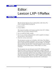
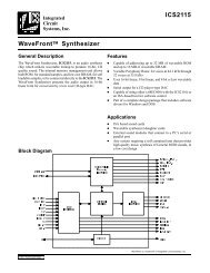
Typical Setup #1<br />
Let’s assume for this setup that we’re recording a guitar and vocal, then<br />
overdubbing another guitar and vocal track while listening to the first tracks.<br />
The following diagram shows a microphone pre-amp and direct box being used<br />
(in this case, the <strong>Audio</strong> Buddy by Midiman), and a stereo sound system. The<br />
pre-amp and direct box are required for the mic and guitar. Many instruments,<br />
such as MIDI modules or keyboards, may be connected directly to the <strong>Delta</strong><br />
<strong>1010</strong>’s inputs.<br />
28
<strong>Delta</strong> <strong>1010</strong> and the<br />
M <strong>Audio</strong> product line line areis<br />
produced by by MIDIMAN.<br />
+4 -10<br />
NOTE: Because improper connections may potentially make very<br />
loud noises, it’s a good idea to have all monitor levels set low or<br />
muted while hooking up audio equipment -- you may even choose<br />
to turn your computer off before making the connections.<br />
Mic<br />
Ch.2<br />
Guitar<br />
Ch. 1<br />
MIDIMAN<br />
<strong>Audio</strong> Buddy<br />
<strong>Delta</strong> <strong>1010</strong><br />
Wordclock<br />
In<br />
Out<br />
Host<br />
Host Cable<br />
Cable<br />
Ins<br />
Outs<br />
8 7 6 5 4 3 2 1<br />
9 VAC<br />
Computer<br />
Sound System<br />
1. Plug the guitar into the channel-1 Line input of the pre-amp. Plug the<br />
microphone into the channel-2 Mic input.<br />
2. Plug the outputs 1 & 2 of the pre-amp into the <strong>Delta</strong> <strong>1010</strong>’s analog inputs 1 &<br />
2. Both are balanced outputs and inputs (respectively), so use a high quality<br />
TRS cable. Most balanced lines run at +4dB line level, so let’s set our +4/-10<br />
switches to +4dB on inputs 1 & 2. The +4 setting requires the +4/-10 button<br />
to be pressed and locked to the "out" position.<br />
3. Plug the hardware outputs 1 & 2 of the <strong>Delta</strong> <strong>1010</strong> to a sound system or power<br />
amp with speakers. If your sound system is a consumer type, set the +4/-10<br />
switches on outputs 1 & 2 to the –10 setting. The –10 setting requires the +4/-<br />
10 button to be pressed and locked to the "in" position.<br />
4. Turn on your equipment in this suggested order: pre-amp, computer, then<br />
sound system.<br />
We’re now physically set up to monitor, record, and play back audio. The next<br />
steps involve configuring the <strong>Delta</strong> Control Panel software and the music<br />
software into which you will be recording. We’ll start with the <strong>Delta</strong> Control<br />
Panel’s "Hardware Settings" page, then the "Patchbay/Router" page, and finally<br />
the "Monitor Mixer" page. We’re not using S/PDIF in this example so we’ll<br />
ignore the S/PDIF page.<br />
29
5. Open the <strong>Delta</strong> Control Panel by double clicking the icon in your Windows<br />
Control Panel, and then click on the ‘Hardware Settings’ tab.<br />
6. Select ‘Internal Xtal’ as the master clock source. This allows the <strong>Delta</strong> <strong>1010</strong> to<br />
derive its sample rates from its internal clock oscillator. ‘Internal Xtal’ is the<br />
default setting for the <strong>Delta</strong> Control Panel, so selecting it may not be necessary<br />
(it may already be selected).<br />
7. Under "CODEC Sample Rate," verify that the "Rate Locked" checkbox is not<br />
activated. This will allow your application software to set the <strong>Delta</strong> <strong>1010</strong><br />
sample rate as it pleases.<br />
8. Since this example will include the use of the monitor mixer, we will activate<br />
the "Reset Rate When Idle" feature. This will make sure the monitor mixer is<br />
running at a decent sample rate while the system is idle – this prevents the<br />
mixer sample rate from being set too low and therefore lowering its frequency<br />
response. Select a sample rate in the "CODEC Sample Rate" group to use as<br />
this idle sample rate. Choose a 44.1kHz or higher setting for best results, and<br />
select the same sample rate you will be using in your application if possible.<br />
We’ve chosen 48,000kHz for this example.<br />
Now click on the <strong>Delta</strong> Control Panel’s "Patchbay/Router" tab. In the first<br />
column of the Patchbay/Router page, click the radio button "Monitor Mixer" to<br />
connect the monitor mixer’s stereo output directly to <strong>Delta</strong> analog outputs OUT1<br />
and OUT2. Now, everything that we hear at outputs 1 & 2 will reflect our<br />
settings in the Monitor Mixer page.<br />
30
Select the "Monitor Mixer" tab of the <strong>Delta</strong> Control Panel. The default Master<br />
Volume fader settings are 0dB and unmuted, and all other faders are set to full<br />
attenuation (-144dB) and muted. We will need to adjust these to our preference.<br />
The screen capture on the next page shows the settings that we wish to achieve.<br />
31
9. In the Mixer Input column labeled "WavOut 1/2," click on each fader handle<br />
and drag it up to the 0dB setting. Also, deactivate (uncheck) each WavOut<br />
1/2 mute box to unmute the channels. This will allow us, once we’ve<br />
recorded into a music software program, to hear those software outputs upon<br />
playback.<br />
10. Using the scroll bar at the bottom of the control panel, scroll to the right until<br />
you see the column labeled "H/W In 1/2." Strum the guitar, and you should<br />
see an indication in the left meter, which represents signal levels from the<br />
<strong>Delta</strong> analog input 1. Test the mic, and you should see an indication in the<br />
right meter, which represents signal levels from <strong>Delta</strong> hardware input 2.<br />
11. Adjust the gain on the pre-amp so that you’re seeing a good level on the input<br />
meters, about –6dB to –3dB in the loudest parts (this is playing it a safe<br />
because you don’t want to hit 0dB and clip). Make similar adjustments for the<br />
microphone, using the right fader. These are the levels at which the signals<br />
will be recorded.<br />
12. Now let’s set the levels at which you will monitor the mic and guitar while<br />
recording. These are not to be confused with the levels that are recorded by<br />
the software – these levels are merely monitor levels that appear in the mixer<br />
outputs (in this case at <strong>Delta</strong> <strong>1010</strong> analog outs 1 & 2). Click on the left fader<br />
handle of H/W In 1/2, and drag it about halfway up. Strum the guitar. If it’s<br />
not loud enough, bring it up all of the way. If it is still not loud enough, you<br />
will have to raise the listening level of your sound system. Make similar<br />
adjustments for the microphone, using the right fader.<br />
13. Now fine-tune your monitor levels. Sing and play guitar, adjusting your<br />
listening levels using the H/W In 1/2 faders so that you have a comfortable<br />
blend of guitar and mic levels.<br />
32
Now is the time to launch your music software and set it up to record and<br />
playback audio tracks. We’re going to speak in general terms here, since setup<br />
within software programs will vary somewhat. Minimize your <strong>Delta</strong> Control<br />
Panel so that you can easily access it from your Windows taskbar. Then open<br />
your music software program.<br />
14. First set up the sample rate in the software application. This operation will<br />
depend on the software. Choose a sample rate that is high enough to capture<br />
the frequency response of the guitar and vocals. A general rule of thumb is to<br />
multiply the highest frequency you would like to capture by two and add<br />
maybe a little on top of that – that gives you a suitable sample rate. Also keep<br />
in mind that if the final results of your work will end up on a CD-ROM<br />
burned from your WAV file, you probably want to use 44.1kHz, the native<br />
sample rate of "redbook" CD audio.<br />
15. In your software application, set the ‘source’ or ‘input port’ to "Left PCM In<br />
1/2 <strong>Delta</strong>-<strong>1010</strong>" on track one, and "Right PCM In 1/2 <strong>Delta</strong>-<strong>1010</strong>" on track<br />
two. Arm the tracks for recording. Track one is now set up to record the<br />
guitar, and track two the microphone. If your software requires this, set the<br />
software’s clock source to ‘<strong>Audio</strong>.’<br />
16. Press record on your software’s transport bar. Record a take of your guitar<br />
and vocals. Understand that while recording, you are monitoring the <strong>Delta</strong><br />
inputs by way of the Monitor Mixer settings for H/W In 1/2, and according<br />
to the selection of ‘Monitor Mixer’ within the Patchbay/Router page. At the<br />
same time, your software is recording from H/W In 1/2 but at the levels that<br />
were set up with the pre-amp.<br />
17. When you are done playing, stop the recording software and rewind the take.<br />
Before playing back what you’ve recorded, you will need to assign the<br />
recorded tracks to output devices on the <strong>Delta</strong> <strong>1010</strong>.<br />
Note: For efficiency’s sake, this step could have taken place while<br />
you were setting up the recording track assignments. However,<br />
since this step only affects playback and does not affect the<br />
recording setup in any way, we’ve placed it here to lessen<br />
confusion.<br />
Assign software track 1 to output device "WavOut 1/2 <strong>Delta</strong>-<strong>1010</strong>" and pan the<br />
track (within your software) all the way to the left (hard left). Then assign track<br />
2 to output device "WavOut 1/2 <strong>Delta</strong>-<strong>1010</strong>" and pan the track all the way to the<br />
hard right. Now, when you start playback, track one (guitar) will be sent to the<br />
<strong>Delta</strong> software (WavOut) output 1, and track two (mic) to <strong>Delta</strong> software<br />
output 2. These two software outputs are inputs to the monitor mixer, therefore<br />
the recorded guitar and mic channels will be sent to the monitor mixer, levels will<br />
be modified by the mixer and the output of the mixer will be heard at analog<br />
outputs 1 & 2.<br />
18. Start playback from your software’s transport bar. Open the <strong>Delta</strong> Control<br />
Panel and go to the Monitor Mixer page. Observe the meters at "WavOut 1/2"<br />
– these are the playback levels of your guitar and mic. Adjust the faders and<br />
33
mute controls so that you may hear the guitar and mic at the appropriate<br />
levels and mix. These are the levels at which you may monitor the prerecorded<br />
tracks while you overdub (record other tracks while listening to the<br />
first) additional parts.<br />
Let’s assume that you like this take, and wish to overdub an additional guitar and<br />
a harmony vocal. We can still use hardware inputs 1 & 2 of the <strong>Delta</strong>. We’re set<br />
up to do so and there’s no reason to change these inputs. Let’s set ourselves up<br />
to overdub these next two tracks. We will record the next two tracks of material<br />
to tracks 3 & 4 of the software:<br />
19. Back in your music program, set the ‘source’ or ‘input port’ to "Left PCM In<br />
1/2 <strong>Delta</strong>-<strong>1010</strong>" on track three, and "Right PCM In 1/2 <strong>Delta</strong>-<strong>1010</strong>" on track<br />
four. Arm the tracks for recording. Track three is now set up to record the<br />
guitar, and track four the microphone. Usually at this point you would want<br />
to return to the <strong>Delta</strong> Control Panel monitor mixer to set up levels. However,<br />
because you will be recording the same instruments that you did on the first<br />
two tracks, you probably won’t need to adjust input or monitoring levels.<br />
20. Press record on your software’s transport bar. Record a take of your new<br />
guitar and vocal tracks. Because you have set up the first two tracks to play<br />
back through the monitor mixer, you should hear those original tracks along<br />
with the ones that you are now recording.<br />
21. When you are done playing, stop the recording software and rewind the take.<br />
Before playing back what you’ve recorded, you will need to assign the newly<br />
recorded tracks to output devices on the <strong>Delta</strong> <strong>1010</strong>. In your software, set the<br />
output ports of tracks three and four to "WavOut 3/4 <strong>Delta</strong>-<strong>1010</strong>." Pan track<br />
three all of the way to the left (hard left), and pan track four hard right. Now<br />
track three (guitar) will be sent to the <strong>Delta</strong> software output 3, and track four<br />
(mic) to <strong>Delta</strong> software output 4.<br />
22. Press play on your software’s transport bar. Understand now that the four<br />
recorded tracks from the software are being sent to WavOut 1, WavOut 2,<br />
WavOut 3, and WavOut 4 simultaneously. Therefore they are all being input<br />
to the monitor mixer and their playback levels can be controlled at the<br />
corresponding channels of the monitor mixer. Open the Monitor Mixer page<br />
of the <strong>Delta</strong> Control Panel and adjust the levels of the four channels according<br />
to your taste. You may also experiment with the Mute and Solo controls while<br />
listening to the playback. Note also that the mixer continues to monitor the<br />
guitar and mic at analog inputs 1 & 2!<br />
At this point, you should be able to see how this multi-tracking session is<br />
developing. As we add more tracks within our music software, we set them to<br />
the next pair of <strong>Delta</strong> software outputs (3/4, then 5/6…), and bring up the faders<br />
of those software inputs in the monitor mixer (WavOut 3/4, WavOut 5/6…). We<br />
continually monitor from the <strong>Delta</strong> hardware outs 1 & 2, via the ‘Mon. Mixer’<br />
setting as the monitor ‘source’ in the Patchbay/Router page, and adjusting our<br />
mix of the software outputs (and the way we monitor our guitar and vocal at the<br />
inputs) via the Monitor Mixer settings.<br />
34
<strong>Delta</strong> <strong>1010</strong> and the<br />
M <strong>Audio</strong> product line line areis<br />
produced by by MIDIMAN.<br />
+4 -10<br />
Notice that if we continue to overdub past track 8, we run out of WavOut devices<br />
to assign to. In this case, you may want to do some of your level mixing within<br />
the software application if it supports it. Most applications will allow you to<br />
assign more than one track to an output device and then set the relative levels of<br />
the tracks within the software, letting the software do the mixing. In this<br />
example you could have assigned all of the playback tracks to "WavOut 1/2" and<br />
let the software handle the mix.<br />
Typical Setup #2<br />
This section contains a multi-tracking example illustrating another way to use the<br />
<strong>Delta</strong> <strong>1010</strong> and its control panel software. We’re going to use multiple inputs<br />
and multiple outputs, so a mixing console that will handle multiple inputs must<br />
be used on the output side of the <strong>Delta</strong> <strong>1010</strong>. A discussion of mixing consoles<br />
and their use will follow in Appendix B. For simplicity in this example we’ll use<br />
pre-amps to get the signal to the <strong>Delta</strong> <strong>1010</strong>, and a mixer connected to a sound<br />
system to handle the multiple outputs.<br />
Let’s say that we’re recording a band. We’ve got 6 mics on the drum set, with the<br />
guitar and bass going ‘direct’ into the pre-amps.<br />
NOTE: Because improper connections can potentially make very<br />
loud noises, it’s a good idea to have monitor levels down while<br />
hooking up audio equipment – you may choose to turn your<br />
computer off before making the connections.<br />
Mixer<br />
MIDIMAN<br />
<strong>Audio</strong> Buddy<br />
MIDIMAN<br />
<strong>Audio</strong> Buddy<br />
MIDIMAN<br />
<strong>Audio</strong> Buddy<br />
MIDIMAN<br />
<strong>Audio</strong> Buddy<br />
<strong>Delta</strong> <strong>1010</strong><br />
Wordclock<br />
In<br />
Out<br />
Host<br />
Host Cable<br />
Cable<br />
Ins<br />
Outs<br />
8 7 6 5 4 3 2 1<br />
9 VAC<br />
Computer<br />
1. Plug the microphones into the mic inputs 1-6 of the pre-amps, and place<br />
around the drums in some strategic fashion (you may want to consult a book<br />
35
on recording techniques). Plug the guitar and bass into the high impedance<br />
inputs 7 & 8 of the pre-amps.<br />
2. Plug the outputs of the pre-amps 1-8 into the hardware inputs 1-8 of the <strong>Delta</strong><br />
<strong>1010</strong>. Usually pre-amp outputs are balanced, so if they are, use TRS cables<br />
and set the <strong>Delta</strong> +4/-10 input switches to the +4dB setting.<br />
3. Plug the hardware outputs 1-8 of the <strong>Delta</strong> <strong>1010</strong> into your mixer’s inputs 1-8<br />
(using 1-8 is recommended for convenience, but not necessary). Some mixers<br />
run at –10 line level, and some at +4. Many mixers may be set either way and<br />
actually have their own +4/-10 switch(es). Let’s assume that our mixer runs<br />
at +4, so set the <strong>Delta</strong> +4/-10 output switches to +4. At this point we’ll assume<br />
that all mixer faders are down, and that the mixer is plugged into a sound<br />
system for monitoring.<br />
We’re now physically set up to monitor, record, and playback audio with the<br />
<strong>Delta</strong> <strong>1010</strong> and related components. The next steps involve the settings in the<br />
<strong>Delta</strong> Control Panel. We’ll use the same settings as Typical Setup #1 for the<br />
<strong>Delta</strong> Control Panel’s ‘Hardware Settings’ page, i.e. "Internal Xtal", "Reset Rate<br />
When Idle" and 48kHz idle sampling rate. The settings that we’ll focus on will<br />
involve the ‘Patchbay/Router’ page. We won’t be using the <strong>Delta</strong> <strong>1010</strong>’s<br />
Monitor Mixer, so we’ll ignore the ‘Monitor Mixer’ page.<br />
4. Open the <strong>Delta</strong> Control Panel software and click on the Patchbay/Router tab.<br />
5. For the first stereo pair, H/W Out 1/2, click the radio button in that column<br />
for "H/W In 1/2." For the second stereo pair, H/W Out 3/4, click the radio<br />
button in that column to "H/W In 3/4." Continuing with this pattern, set the<br />
H/W Out 5/6 column to "H/W In 5/6," and the H/W Out 7/8 column to<br />
"H/W In 7/8." Using these settings for the Patchbay/Router page connects<br />
each hardware input directly to a hardware outputs. These settings will allow<br />
us to monitor the inputs to the <strong>Delta</strong> <strong>1010</strong> (drums, guitar, and bass) while we<br />
are recording.<br />
6. Minimize the <strong>Delta</strong> Control Panel to the Windows taskbar.<br />
7. Open your music software program. Set up eight tracks for recording:<br />
36
Track one -- Left PCM In 1/2 <strong>Delta</strong>-<strong>1010</strong><br />
Track two -- Right PCM In 1/2 <strong>Delta</strong>-<strong>1010</strong><br />
Track three -- Left PCM In 3/4 <strong>Delta</strong>-<strong>1010</strong><br />
Track four -- Right PCM In 3/4 <strong>Delta</strong>-<strong>1010</strong><br />
Track five -- Left PCM In 5/6 <strong>Delta</strong>-<strong>1010</strong><br />
Track six -- Right PCM In 5/6 <strong>Delta</strong>-<strong>1010</strong><br />
Track seven -- Left PCM In 7/8 <strong>Delta</strong>-<strong>1010</strong><br />
Track eight -- Right PCM In 7/8 <strong>Delta</strong>-<strong>1010</strong><br />
8. Now we want to set up the output ports for the eight tracks.<br />
Track one -- WavOut 1/2 <strong>Delta</strong>-<strong>1010</strong>, panned hard left.<br />
Track two -- WavOut 1/2 <strong>Delta</strong>-<strong>1010</strong>, panned hard right.<br />
Track three -- WavOut 3/4 <strong>Delta</strong>-<strong>1010</strong>, panned hard left.<br />
Track four -- WavOut 3/4 <strong>Delta</strong>-<strong>1010</strong>, panned hard right.<br />
Track five -- WavOut 5/6 <strong>Delta</strong>-<strong>1010</strong>, panned hard left.<br />
Track six -- WavOut 5/6 <strong>Delta</strong>-<strong>1010</strong>, panned hard right.<br />
Track seven -- WavOut 7/8 <strong>Delta</strong>-<strong>1010</strong>, panned hard left.<br />
Track eight -- WavOut 7/8 <strong>Delta</strong>-<strong>1010</strong>, panned hard right.<br />
9. Bring up the meter view in your music software, and let’s start to get some<br />
levels here. Let’s say that your hardware input 1 is the kick drum mic. Have<br />
the drummer play the kick drum and raise the input gain on your pre-amp<br />
channel 1 until you see a level of –6dB or so. This is your recording level. At<br />
the same time you can begin to raise the faders on your mixer until you hear<br />
the kick drum at a comfortable volume. This is your monitor level. Do the<br />
same for each instrument.<br />
NOTE: You could view the record levels from the Monitor Mixer<br />
page also. The levels appearing in H/W In 1/2 through H/W In 7/8<br />
will represent the signal appearing at the hardware inputs. We are<br />
not monitoring via the Monitor Mixer, however, so no fader levels in<br />
this page will apply or are needed in this example.<br />
37
Once this is done, we are set up and ready to record. Close or minimize your<br />
software’s meter view at this point.<br />
10. Arm tracks one through eight for recording and press the record button on<br />
your music software’s transport bar.<br />
11. Once you have a take that you think is worth listening to, stop recording and<br />
rewind. Maximize the <strong>Delta</strong> Control Panel from your Windows taskbar.<br />
12. Click the Patchbay/Router tab. In the first column, H/W Out 1/2, click the<br />
radio button "WavOut 1/2" so that our monitoring source is now the software<br />
outputs from the music program. Set the H/W Out 3/4 column to "WavOut<br />
3/4," the H/W Out 5/6 column to "WavOut 5/6," and finally, set the H/W<br />
Out 7/8 column to "WavOut 7/8." Now all of the software outputs of the<br />
music program are connected to the corresponding hardware outputs.<br />
Minimize the control panel.<br />
13. Click play on the transport bar of your music software. If the take is<br />
satisfactory, disarm tracks one through eight and revel in your success. If you<br />
wish to redo the tracks, "undo" the recording in your software, repeat steps 10<br />
through 13 in this section.<br />
Using the <strong>Delta</strong> <strong>1010</strong> and the <strong>Delta</strong> Control Panel software in this manner may<br />
be your choice when using a mixing console to control the monitor and playback<br />
levels. If this were a real recording situation and you wished to add vocals or<br />
other instruments as overdubs, you might want to combine all of the drums (for<br />
instance) to one stereo pair of outputs (WavOut 1/2 <strong>Delta</strong>-<strong>1010</strong>, for example).<br />
This would ‘free up’ several channels for monitoring the overdubs.<br />
Typical Setup #3<br />
Let’s look at a setup that involves a typical transfer of information from DAT to<br />
computer and back to DAT. Here, we’ll be using the <strong>Delta</strong> <strong>1010</strong>’s S/PDIF I/O,<br />
plus one of the analog output stereo pairs.<br />
NOTE: Because improper connections can potentially make very<br />
loud noises, it’s a good idea to have monitor levels down while<br />
hooking up audio equipment -- you may even choose to turn your<br />
computer off before making the connections.<br />
In this example, we will connect a DAT to the <strong>Delta</strong> <strong>1010</strong> PCI Host card using<br />
coaxial S/PDIF cables (75-ohm impedance RCA-to-RCA). We’ll also connect<br />
the <strong>1010</strong>’s analog outputs to a sound system for monitoring purposes. A setup<br />
like this might be used to transfer a number of mixes from a DAT into an audio<br />
editing program, performing the appropriate edits, and then transferring the<br />
edited material back to DAT.<br />
The example below may at first look long and laborious, but you will find that<br />
most of the settings are factory defaults and will rarely need to be modified.<br />
38
<strong>Delta</strong> <strong>1010</strong> and the<br />
M <strong>Audio</strong> product line line areis<br />
produced by by MIDIMAN.<br />
<strong>Delta</strong> <strong>1010</strong><br />
Wordclock<br />
In<br />
Out<br />
Host<br />
Host Cable<br />
Cable<br />
Ins<br />
+4 -10<br />
Outs<br />
8 7 6 5 4 3 2 1<br />
9 VAC<br />
<strong>Delta</strong> <strong>1010</strong> PCI<br />
Card in Computer<br />
Sound System<br />
DAT<br />
Transferring from DAT to <strong>Delta</strong> <strong>1010</strong><br />
1. Connect the DAT’s coaxial S/PDIF output to the S/PDIF In of the <strong>Delta</strong> <strong>1010</strong><br />
PCI host card, using a good quality cable.<br />
2. Connect the <strong>1010</strong> analog outputs 1 & 2 to some type of amplified sound<br />
system. The sound system should be equipped with speakers or headphones.<br />
Set the +4/-10 switches on OUT1 and OUT2 to be compatible with<br />
that sound system’s inputs.<br />
3. Because you will be recording from the S/PDIF input, you will need to set up<br />
the <strong>Delta</strong> <strong>1010</strong> to synchronize its master clock with the S/PDIF input. To do<br />
this, open the Hardware Settings page of the control panel software. Under<br />
Master Clock, select "S/PDIF In."<br />
4. Next, you will need to tell your application software the expected sample rate.<br />
We’ll use 44.1 kHz in this example. Therefore, on the Hardware Settings page,<br />
set the "S/PDIF Sample Rate" to 44,100.<br />
5. In order to monitor the digital signal coming into the <strong>1010</strong>, switch to the<br />
Patchbay/Router page of the control panel software. In the "H/W Out 1/2"<br />
39
<strong>Delta</strong> <strong>1010</strong> and the<br />
M <strong>Audio</strong> product line line areis<br />
produced by by MIDIMAN.<br />
column, select the radio button named "S/PDIF In." This will copy all S/PDIF<br />
input audio directly over to the analog outputs – therefore in this example, the<br />
monitor mixer will be completely bypassed. Once this assignment is made,<br />
you may play the DAT material at any time and verify that it is making it into<br />
the <strong>Delta</strong> <strong>1010</strong> successfully. This can be done regardless of whether or not<br />
your recording software is open.<br />
6. Within your recording software, select "S/PDIF In <strong>Delta</strong>-<strong>1010</strong>," as the audio<br />
input device. The <strong>Delta</strong> input appears as a stereo pair.<br />
7. Start your software recording and then start your DAT material playing. You<br />
should be able to hear the DAT material through your sound system.<br />
<strong>Delta</strong> <strong>1010</strong><br />
Wordclock<br />
In<br />
Out<br />
Host<br />
Host Cable<br />
Cable<br />
Ins<br />
+4 -10<br />
Outs<br />
8 7 6 5 4 3 2 1<br />
9 VAC<br />
<strong>Delta</strong> <strong>1010</strong> PCI<br />
Card in Computer<br />
DAT<br />
Sound System<br />
Transferring from <strong>1010</strong> to DAT, monitoring with DAT<br />
1. Connect the <strong>Delta</strong> <strong>1010</strong>’s S/PDIF Out to the DAT’s coaxial S/PDIF Input<br />
using a good quality cable.<br />
2. Connect the DAT analog outputs to some type of amplified sound system.<br />
The sound system should be equipped with speakers or headphones.<br />
3. Because you will be playing back at the recorded sample rate, you will want<br />
to set the <strong>Delta</strong> <strong>1010</strong>’s master clock to use the <strong>1010</strong> internal crystal. Do this by<br />
40
opening the Hardware Settings page of the <strong>Delta</strong> Control Panel software and<br />
under Master Clock, selecting "Internal Xtal." Also, under the Codec Sample<br />
Rate section you may uncheck "Rate Locked" if it is previously checked. This<br />
allows for more flexible sample rate playback.<br />
4. In order to verify proper S/PDIF Output routing, open the Patchbay/Router<br />
page of the control panel software. In the "H/W Out S/PDIF" column, select<br />
the radio button named "WavOut S/PDIF." Now everything that is sent by<br />
your software to the "WavOut S/PDIF" device will be routed to the hardware<br />
S/PDIF output, and consequently to the DAT.<br />
5. Next let’s make sure the S/PDIF output format is correct. Open the S/PDIF<br />
page of the control panel software. Under Digital Output Format, choose<br />
"Consumer." Uncheck "Advanced" if it is checked previously. Now click on<br />
the "Restore Defaults" button to set the default S/PDIF outgoing status bits.<br />
This will disable copy protection and also set the emphasis to "none," allowing<br />
the DAT to accept and record the audio properly.<br />
6. Within your recording software, select "WavOut S/PDIF <strong>Delta</strong>-<strong>1010</strong>" as the<br />
audio output device.<br />
7. Start your DAT recording and then start your software playing. You should be<br />
able to hear the DAT material through your sound system. This verifies that<br />
the digital audio is making it into the DAT correctly.<br />
41
Troubleshooting<br />
This section addresses potential problems that can occur in all operating system<br />
environments, with emphasis on hardware troubleshooting. Within the PC<br />
environment there are a limited number of hardware resources (I/O addresses,<br />
IRQs, and DMA channels) available for use. Since audio cards require many<br />
resources, most audio card installation problems arise from unavailable or<br />
improperly set resources. This is important enough to repeat:<br />
IMPORTANT: Most sound card installation problems result from<br />
attempting to use system resources (IRQs, address locations)<br />
already in use by other hardware (or software acting as “virtual”<br />
hardware) in the system.<br />
The <strong>Delta</strong> <strong>1010</strong> has been carefully designed to minimize the number of resources<br />
consumed (it requires just one IRQ and does not require any DMA channel<br />
resources). It is also capable of sharing an IRQ in some cases. However, the<br />
possibility of resource conflicts still exists due to the nature of the Windows<br />
environment. Many resource conflicts are automatically recognized by<br />
Windows’ Plug-and-Play (PnP) system. When a resource conflict is detected, it<br />
is displayed in the Windows Device Manager. The Device Manager places a<br />
yellow exclamation point on top of the icon associated with the problem device.<br />
For an example of how the Device Manager should look when a <strong>Delta</strong> <strong>1010</strong> is<br />
successfully installed, see the "Verifying Windows Driver Installation" section of<br />
this manual. If a yellow exclamation point does appear over your <strong>Delta</strong> <strong>1010</strong><br />
icon, you may have a resource conflict. There are several ways to approach this<br />
problem.<br />
NOTE: When resolving conflicts between PnP and non-PnP<br />
devices, it is recommended to re-adjust the resource settings of<br />
the non-PnP device first. Typically, Windows is only aware of the<br />
resource settings of the installed PnP devices and has no<br />
information available to it for adjusting the PnP devices’ resources<br />
around those of the non-PnP devices. The exceptions to this are<br />
when: (1) a non-PnP device has a true Windows 98/95 driver<br />
written for it, (2) the BIOS setup allows reserving an IRQ for a<br />
legacy device as opposed to a PnP device, or (3) resource<br />
requirements for the non-PnP device have been manually entered<br />
into the Windows Device Manager. In these cases Windows is<br />
aware of the non-PnP device’s resource requirements.<br />
One of the quickest ways to change the resources assigned to a PCI card like the<br />
<strong>Delta</strong> <strong>1010</strong> is to merely relocate the card to another PCI slot. With the<br />
computer’s power off, remove the <strong>Delta</strong> <strong>1010</strong> from its current PCI slot, move it<br />
to another available PCI slot, and turn your computer back on. More often than<br />
not, this will change the IRQ assignment of the <strong>Delta</strong> <strong>1010</strong> when you re-enter<br />
Windows. After returning to Windows, follow the steps outlined in the<br />
42
"Verifying Windows Driver Installation" section of this manual. It might take<br />
more than one PCI slot relocation to find an open IRQ.<br />
If relocating your card to another PCI slot does not cure the <strong>Delta</strong> <strong>1010</strong>’s<br />
conflict(s), then you must do some further investigation to determine the exact<br />
nature of the conflict(s). Again, go to the Windows Device Manager, highlight<br />
the <strong>Delta</strong> <strong>1010</strong> or other devices with conflicts and click the "<strong>Pro</strong>perties" button<br />
at the bottom of the Device Manager window. This will open the properties page<br />
for that device. Select the "Resources tab" in order to view the resource<br />
assignments, plus possible conflicts. You may learn more about a conflict by<br />
highlighting each item one-by-one (done by clicking on them, or scrolling<br />
through the list using your keyboard cursor keys) and examining the "Conflicting<br />
resource list:" at the bottom of the box.<br />
Sometimes it is possible that a resource problem is not showing up in the<br />
conflicting resource list or as a yellow exclamation point in the Device Manager.<br />
If you have any doubt about the configuration of your device (or just want to<br />
double-check), you can view all of the devices and their assigned resources by<br />
highlighting "Computer" at the top of the Device Manager list and clicking the<br />
<strong>Pro</strong>perties button. This will allow you to view a list of assigned IRQ numbers on<br />
the left, and the associated devices on the right. If a number does not show up<br />
in this list, it means that it is available for use. Look also for IRQs that are shared<br />
by more than one device. While the <strong>Delta</strong> <strong>1010</strong> may share an IRQ with some<br />
devices, not all devices are capable of sharing IRQs. An entry that reads "IRQ<br />
Holder for PCI Steering" along with an installed PCI device (such as the <strong>Delta</strong><br />
<strong>1010</strong>) is normal. If you see another device showing up on the same IRQ as the<br />
<strong>Delta</strong> <strong>1010</strong> (such as a video card, SCSI adapter, or USB Host Controller), then it<br />
is possible that this is the source of the conflict. Typically, if you move one of<br />
the conflicting cards to another PCI slot, an IRQ conflict will disappear.<br />
Address conflicts are rare amongst PCI devices, but if there is no obvious IRQ<br />
conflict, why not check for I/O Address conflicts while in the Device Manager?<br />
43
You may view the list of assigned I/O addresses by selecting the "Input/output<br />
(I/O)" radio button below the "Interrupt Request (IRQ)" radio button at the top<br />
of the Device Manager page. I/O addresses are displayed as 16-bit hexadecimal<br />
numbers, therefore one might note that an address of 300h (the default address<br />
of the Winman 4X4/s, for instance), will read "0300" in this list.<br />
If scanning all the resource lists in the Device Manager does not provide an<br />
answer or clue to the resource conflict, you might want to exit Windows and do<br />
a final inspection of your computer’s BIOS setup. Some newer BIOS’s (see your<br />
computer manual) allow the reservation of an IRQ for each PCI slot on the<br />
motherboard. This may be very handy in resolving IRQ assignments for PCI<br />
devices.<br />
Also, sometimes a BIOS is configured to direct a particular IRQ to an ISA legacy<br />
device (non-PnP ISA card), and needs to be told to look for a PCI/ISA PnP device<br />
(some systems default to this, especially with IRQs 3 and 4). Consult your<br />
computer or motherboard manual for advice on how to do this.<br />
Finally, with some systems you will reach the dead-end realization that you have<br />
no available IRQ’s – every one of them is assigned to some device in the system.<br />
This most typically occurs with pre-packaged computers made by the big-name<br />
O.E.M. computer companies. These computers have so many features packed<br />
into them that every IRQ is consumed. In this type of situation, some kind of<br />
reconfiguring or reprioritizing your system is in order. Optionally, Windows<br />
may allow you to create a second "hardware configuration" which disables some<br />
of the installed devices and makes their resources available for general use. See<br />
your Windows documentation for information on this subject.<br />
44
Troubleshooting Tips for Frequently Asked<br />
Questions<br />
<strong>Pro</strong>blem: No Sound.<br />
Possible Cause 1: The <strong>Delta</strong> <strong>1010</strong> hardware or software device<br />
drivers are not properly installed. See the installation sections of this<br />
manual for further information.<br />
Possible Cause 2: There is a resource conflict between the <strong>Delta</strong> <strong>1010</strong><br />
and another device in your computer. Check the <strong>Delta</strong> <strong>1010</strong> configuration<br />
(Address, IRQ) against those of the other installed devices. If necessary, change<br />
the settings for the one or more of the devices.<br />
Possible Cause 3: Your application software has not been properly<br />
configured to use the <strong>Delta</strong> <strong>1010</strong> as its audio output device.<br />
Possible Cause 4: Misrouted outputs in the <strong>Delta</strong> Control Panel. Check<br />
the <strong>Delta</strong> Control Panel’s Patchbay/Router page to verify output routing<br />
assignments. Also, make sure that if the output is routed from the digital mixer,<br />
that the mixer’s faders, solo and mute controls are set up properly.<br />
Possible Cause 5: Improper connections of the audio accessories.<br />
Verify that the <strong>Delta</strong> <strong>1010</strong> analog audio outputs are properly connected to a<br />
digital mix deck or external mixer/amplifier, or the S/PDIF Out is connected to<br />
an external digital audio device capable of receiving S/PDIF.<br />
<strong>Pro</strong>blem: No visual activity on <strong>Audio</strong> Input volume (VU) meters of user<br />
software.<br />
Possible Cause 1: The <strong>Delta</strong> <strong>1010</strong> input devices are not properly<br />
selected in the user’s application software.<br />
Possible Cause 2: If the software is recording from the <strong>Delta</strong> <strong>1010</strong>’s<br />
monitor mixer device, be sure that the mixer’s faders, solo and mute controls are<br />
set up properly.<br />
Possible Cause 3: Improper connections to audio accessories.<br />
<strong>Pro</strong>blem: Repetitious Sound.<br />
Possible Cause: An IRQ resource conflict. Often this will result in a<br />
small segment of sound (0.5 to 1 second) repeating itself over and over,<br />
sometimes completely locking up the computer. See the general troubleshooting<br />
suggestions at the beginning of this section.<br />
45
<strong>Pro</strong>blem: I’m getting some pops and clicks in my audio recording.<br />
Possible Cause 1: Input levels are too "hot," causing clipping or input<br />
distortion. Make sure you have the proper signal levels set on the rear of the<br />
<strong>Delta</strong> <strong>1010</strong> rack-mount unit. "+4" can handle much hotter signals than "-10." If<br />
you find that you are still clipping at the +4 setting, you will need to turn down<br />
the audio at the source.<br />
Possible Cause 2: If you are recording from the S/PDIF input, but you<br />
have the <strong>Delta</strong> <strong>1010</strong>’s master clock set to something other than the S/PDIF input,<br />
you are recording an out-of-sync S/PDIF stream. This can result in lost or bogus<br />
samples being recorded.<br />
Possible Cause 3: Your application software may not have the proper<br />
audio buffer sizes set. Each software application handles this differently, but<br />
typically there is somewhere in the software’s setup to set the size of the<br />
playback and recording buffers used by the application. Some applications also<br />
require you to run a card calibration (sometimes called "profiling") the first time<br />
you use the software with a new audio card.<br />
Possible Cause 4: Some accelerated graphics cards use excessive<br />
amounts of system bandwidth, preventing the recording buffer of an audio card<br />
from keeping up with demand. This can cause clicks in the recording. Reducing<br />
or turning off the graphics card’s graphics acceleration feature often resolves this<br />
problem. In Windows, the level of graphics acceleration is accessed from Start<br />
|Settings | Control Panel | System | Performance | Graphics.<br />
<strong>Pro</strong>blem: I’m getting some pops and clicks in my monitoring signal, even<br />
when my system is idle.<br />
Possible Cause: If the S/PDIF input is not muted in the monitor mixer,<br />
and you have the <strong>Delta</strong> <strong>1010</strong>’s master clock set to something other than the<br />
S/PDIF input, you are monitoring an out-of-sync S/PDIF stream. This can result<br />
in lost or bogus samples being recorded.<br />
<strong>Pro</strong>blem: The sound from the monitor mixer is muffled. It sounds as if it<br />
were running through a mixer with the treble control turned all the way down!<br />
Possible Cause: The current <strong>Delta</strong> <strong>1010</strong> sample rate is too low. The<br />
monitor mixer is a digital device that runs at the current sample rate of the <strong>Delta</strong><br />
<strong>1010</strong> board. The frequency response of the mixer is roughly one-half of the<br />
sample rate. There is no way to prevent this lost frequency response while<br />
playing back or recording at a low sample rate. However, it may be prevented<br />
when the system is idle. See the "CODEC SAMPLE RATE" paragraph of the<br />
section ‘Hardware Settings Page’ for more information.<br />
46
Appendix A - Technical Specs<br />
Analog <strong>Audio</strong><br />
Peak Analog Input Signal:<br />
+20.2dBu (+4dBu setting),<br />
+2.1dBV (-10dBV setting)<br />
Peak Analog Output Signal:<br />
+20.0dBu (+4dBu setting),<br />
+2.0dBV (-10dBV setting)<br />
Dynamic Range:<br />
Outputs:<br />
Inputs:<br />
108dB (a-weighted),<br />
109dB (a-weighted)<br />
THD (at 0dBFS):<br />
Outputs: less than 0.0015%,<br />
Inputs: less than 0.001%<br />
Frequency Response:<br />
Input Impedance:<br />
Input Connectors:<br />
Output Connectors:<br />
22Hz - 22kHz, -0.3,-0.2dB<br />
10k ohms minimum<br />
1/4" female TRS-type, balanced or<br />
unbalanced<br />
1/4" female TRS-type, balanced or<br />
unbalanced<br />
Digital <strong>Audio</strong><br />
Digital Input Format:<br />
Digital Input Sample Rate:<br />
Digital Output Format:<br />
S/PDIF coaxial, 0.5V to 5V peak-topeak.<br />
8kHz to 96kHz.<br />
S/PDIF coaxial, 0.5V peak-to-peak;<br />
AES/EBU data stream over S/PDIF<br />
coaxial.<br />
Digital Output Sample Rate:<br />
Word Clock Input Rate:<br />
Word Clock Output Rate:<br />
8kHz to 96kHz.<br />
8kHz to 50kHz.<br />
8kHz to 96kHz.<br />
47
Adapter Resource Requirements<br />
IRQ:<br />
I/O Addresses:<br />
DMA Channels:<br />
One required<br />
Four blocks: 32, 16, 16, and 64 bytes<br />
None required<br />
Appendix B - If You Use An External Mixer...<br />
Our main objective is to get the signal we want to record to the <strong>Delta</strong> <strong>1010</strong>, and<br />
to monitor the outputs from the <strong>Delta</strong> <strong>1010</strong>. The <strong>1010</strong> has a mixer contained on<br />
its chip that allows you to mix hardware inputs and software outputs and send it<br />
to an analog stereo output pair and/or the S/PDIF out. The <strong>1010</strong> also allows you<br />
to record that mix into your music software as a hardware input. Still, some of<br />
you may choose to use a mixing console to achieve your multi-tracking goals.<br />
A mixing console (sometimes referred to as mixing ‘board’ or ‘desk’) that is<br />
designed for multi-track recording has the ability to fulfill these two basic<br />
functions -- getting the signal to the recording device, and receiving the outputs<br />
of that recording device for mixing or monitoring. In this sense, a recording<br />
console is two mixers in one. A mixer designed for recording will also have the<br />
ability to send to one or more mixdown decks, to monitor these mixdown decks,<br />
to control separate control room and studio listening levels, as well as other<br />
recording-specific functions.<br />
There are two basic layouts for the recording console, "split section" and "inline."<br />
The split section design is arranged with a recording or ‘channel’ section<br />
(to send the signal to the recording device) side-by-side with a monitoring<br />
section (to receive the outputs of the recording device). The in-line design has the<br />
recording and monitoring sections "in line" within each channel module, so that<br />
each channel has two line inputs.<br />
The recording section is distinguished by its bussing system, which takes the<br />
recording channel signal through a summing matrix to multiple outputs- usually<br />
in multiples of eight. It could be said that an ‘8-buss system’ is designed for 8<br />
track recording, and a 24-buss system for 24 track recording, etc., but this is not<br />
written in stone.<br />
What we are describing here is the extreme- a professional, costly piece of gear<br />
that has been purchased for this one specialized purpose. There are features<br />
inherent in other types of consoles, however, that will allow us to perform these<br />
two separate functions of recording and monitoring. A sound reinforcement or a<br />
broadcast console, and in some cases a recording console, might offer a bussing<br />
48
system in the form of "sub-mix outs." These are usually arranged in stereo pairs<br />
with a set of level control faders for each pair. This configuration can be<br />
effectively used for recording, as long as the record channels are taken out of the<br />
stereo buss. The difference here is that there is no real distinction between the<br />
recording and monitoring sections.<br />
Some line mixers have a number of effect or auxiliary sends for each channel.<br />
These sends will have their own individual level control and will receive the<br />
signal either pre fader or post fader, i.e. either independent or dependent on that<br />
channel’s fader level. It is possible to use these "aux sends" to send a signal to<br />
the recording device. A pre fader send is certainly preferable, since this will allow<br />
for a recording level that is separate from the monitoring level.<br />
The bottom line here is that you can not use the ‘main output’ of your mixer to<br />
send a signal to the recording device, and then take the outputs of that recording<br />
device back into the mixer (whose signal also goes to the main out). This creates<br />
a feedback loop, bad for your eardrums and bad for your equipment.<br />
One modern console design gets around that by offering an "alt out," which is an<br />
alternate stereo buss or output. When selecting ‘alt out’ on a channel, it mutes<br />
that channel to the stereo buss and redirects it to the alt out buss. This could be<br />
viewed as a 2-buss system, and can be used effectively for recording purposes.<br />
In our Typical Setup 1 and 2 in the previous section, we used pre-amps to handle<br />
the recording. A line mixer that simply received the line outputs from the <strong>1010</strong><br />
and mixed them to stereo could handle the monitoring needs. Hopefully, the<br />
information here will give you some insight into how to use the gear that you<br />
own, or what to look for if you are seeking additional equipment to facilitate your<br />
hard disk recording.<br />
49
Limited Lifetime Warranty<br />
MIDIMAN warrants that this product is free of defects in materials and<br />
workmanship under normal use so long as the product is: owned by the original<br />
purchaser; the original purchaser has proof of purchase from an authorized<br />
MIDIMAN dealer; and the purchaser has registered his/her ownership of the<br />
product by sending in the completed warranty card.<br />
This warranty explicitly excludes power supplies and included cables which may<br />
become defective as a result of normal wear and tear.<br />
In the event that MIDIMAN receives written notice of defects in materials or<br />
workmanship from such an original purchaser, MIDIMAN will either replace the<br />
product, repair the product, or refund the purchase price at its option. In the event<br />
any repair is required, shipment to and from MIDIMAN and a nominal handling<br />
charge shall be born by the purchaser. In the event that repair is required, a<br />
Return Authorization number must be obtained from MIDIMAN. After this<br />
number is obtained, the unit should be shipped back to MIDIMAN in a protective<br />
package with a description of the problem and the Return Authorization clearly<br />
written on the package.<br />
In the event that MIDIMAN determines that the product requires repair because<br />
of user misuse or regular wear, it will assess a fair repair or replacement fee. The<br />
customer will have the option to pay this fee and have the unit repaired and<br />
returned, or not pay this fee and have the unit returned unrepaired.<br />
The remedy for breach of this limited warranty shall not include any other<br />
damages. MIDIMAN will not be liable for consequential, special, indirect, or<br />
similar damages or claims including loss of profit or any other commercial<br />
damage, even if its agents have been advised of the possibility of such damages,<br />
and in no event will MIDIMAN's liability for any damages to the purchaser or<br />
any other person exceed the price paid for the product, regardless of any form of<br />
the claim. MIDIMAN specifically disclaims all other warranties, expressed or<br />
implied. Specifically, MIDIMAN makes no warranty that the product is fit for<br />
any particular purpose.<br />
This warranty shall be construed, interpreted, and governed by the laws of the<br />
state of California. If any provision of this warranty is found void, invalid or<br />
unenforceable, it will not affect the validity of the balance of the warranty, which<br />
shall remain valid and enforceable according to its terms. In the event any<br />
remedy hereunder is determined to have failed of its essential purpose, all<br />
limitations of liability and exclusion of damages set forth herein shall remain in<br />
full force and effect.<br />
50
Notes:<br />
51
D<strong>1010</strong>-111700<br />
52