Neutrik NPPA-TT-PT.pdf - Free Pro Audio Schematics
Neutrik NPPA-TT-PT.pdf - Free Pro Audio Schematics
Neutrik NPPA-TT-PT.pdf - Free Pro Audio Schematics

Create successful ePaper yourself
Turn your PDF publications into a flip-book with our unique Google optimized e-Paper software.
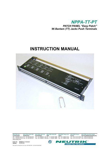
<strong>NPPA</strong>-<strong>TT</strong>-<strong>PT</strong><br />
PATCH PANEL “Easy Patch”<br />
96 Bantam (<strong>TT</strong>) Jacks Push Terminals<br />
INSTRUCTION MANUAL<br />
NEUTRIK AG NEUTRIK Zürich AG NEUTRIK (UK) Ltd. NEUTRIK USA INC. NEUTRIK Tokyo Ltd. NEUTRIK France NEUTRIK Vertriebs GmbH<br />
Liechtenstein Switzerland Great Britain USA Japan France Germany/Netherlands/Austria<br />
Tel.: +423/237 24 24 Tel.: +41 44/736 5010 Tel.: +44 1983/811 441 Tel.: +1 732/901 9488 Tel.: +81 3/3663 4733 Tel.: +33 1/4131 6750 Tel.: +49 8131/28 08 90<br />
Fax: +423/232 53 93 Fax: +41 44/736 5011 Fax: +44 1983/811 439 Fax: +1 732/901 9608 Fax: +81 3/3663 4796 Fax: +33 1/4131 0511 Fax: +49 8131/28 08-30<br />
www.neutrik.com<br />
Draft. Nr.: BDA80-2/ 3102M0801<br />
Update: 06.06.2007<br />
Data subject to change without prior notice. ©2007 NEUTRIK . ALL RIGHTS RESERVED.
S<br />
T<br />
R<br />
S<br />
R<br />
T<br />
S<br />
R<br />
T<br />
TN<br />
RN<br />
S<br />
TN<br />
RN<br />
T<br />
R<br />
S<br />
R<br />
T<br />
S<br />
R<br />
T<br />
S<br />
R<br />
T<br />
S<br />
R<br />
T<br />
S<br />
TN<br />
RN<br />
TN<br />
RN<br />
S<br />
T<br />
R<br />
T<br />
R<br />
S<br />
R<br />
T<br />
S<br />
R<br />
T<br />
S<br />
R<br />
T<br />
S<br />
R<br />
T<br />
<strong>NPPA</strong>-<strong>TT</strong>-<strong>PT</strong> Instruction Manual<br />
Index<br />
1. Electrical configuration.................................................................................................3<br />
2. Replacement of Jack Pairs..........................................................................................4<br />
3. Reconfiguration by hand..............................................................................................5<br />
4. Grounding variations ...................................................................................................7<br />
5. Wiring ..........................................................................................................................8<br />
6. Cable retention to the unit............................................................................................9<br />
7. Channel identification ..................................................................................................9<br />
8. Technical data ...........................................................................................................11<br />
9. Wiring Diagram..........................................................................................................12<br />
10. Ordering Information................................................................................................13<br />
Dimensional Drawings “Easy Patch” <strong>NPPA</strong>-<strong>TT</strong><br />
1 2 3 4 5 6 7 8 9 10 11 12 13 14 15 16 17 18 19 20 25 26 27 28<br />
48<br />
Half Normalled Bottom<br />
Half Normalled Top<br />
Full Normalled<br />
Parallel<br />
Isolated<br />
Grounding<br />
Common Signal Ground<br />
Upper Row<br />
Chassis Ground<br />
Common Signal Ground<br />
Bottom Row<br />
Soldering Pads<br />
to connect<br />
Individual Grounds to Common Ground<br />
Module Arrangement<br />
Top View<br />
Key<br />
<strong>NPPA</strong>-<strong>TT</strong>-S<br />
Front panel<br />
Cable retention bar<br />
Top cover<br />
Page 2 of 13
<strong>NPPA</strong>-<strong>TT</strong>-<strong>PT</strong> Instruction Manual<br />
1. Electrical configuration<br />
The <strong>Neutrik</strong> ”Easy Patch” Patch Panel is fitted with high quality, long life NJ3<strong>TT</strong>A gold plated<br />
double contact jacks (2 x 48). This Patch Panel is an innovative and compact patching system<br />
(just 1 U high) for 19” rack mounting. Robustly housed in black coated steel shell and featuring<br />
precision aluminum fittings it is built to last. The <strong>Neutrik</strong> "Easy Patch” is suitable for analog and<br />
digital audio signals.<br />
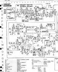
The ”Easy Patch” is available in five normalling configurations (fully loaded).<br />
• half normalled bottom row<br />
• half normalled top row<br />
• full normalled<br />
• parallel<br />
• isolated<br />
Configuration Chart<br />
Furthermore individual jack pairs can be changed to combine various normallings within one<br />
panel quickly and without fuss. This is even possible while the panel is "on air". For this we offer<br />
pre-configured jack pairs (NJ3<strong>TT</strong>A-4-*).<br />
In case of emergency the normalling for individual jack pairs can be changed by the use of<br />
normalling bars. Normalling bars to change the normalling of 4 channels are included.<br />
Page 3 of 13
<strong>NPPA</strong>-<strong>TT</strong>-<strong>PT</strong> Instruction Manual<br />
2. Replacement of Jack Pairs<br />
Each individual jack pair can be exchanged quickly and without fuss even while the panel is "on<br />
air". For replacement simply remove the easy accessible jack pairs.<br />
Module consisting of 2 Jack Pairs<br />
Remove Front Panel by unscrewing the 3 black cross-recessed<br />
screws (M3x8 Taptite), remove the two side-stops.<br />
Push out the channel identification strips.<br />
Pull one module out of the casing using the supplied<br />
disassembling pliers<br />
Alternatively the jack pairs may be pulled out by the use of two<br />
Bantam plugs (diagonally plugged in).<br />
Page 4 of 13
<strong>NPPA</strong>-<strong>TT</strong>-<strong>PT</strong> Instruction Manual<br />
The two jack pairs have to be re-assembled in the right way so<br />
that the thicker body marked “left” is put on the left side with<br />
the mark outside and readable.<br />
To complete, push the new jack pairs into the casing again with the mark on the left side (If<br />
more than one module are removed always assemble from the center to the right or left side<br />
and be careful that the keys on the left side of the jack pairs find their guiding slots. If all jack<br />
pairs are removed start at the casing support in the center and assemble to the right and left<br />
side). Slide in again the channel identification strips (best from the outside inwards) and fix the<br />
front panel with the black cross-recessed screws. Don’t forget to insert the side-stops before<br />
fixing the screws (see page 10).<br />
3. Reconfiguration by hand<br />
Please note, in case of emergency the normalling can by changed by hand by the use of<br />
normalling bars. For easy and safe modification work we recommend our preconfigured jack<br />
pairs (NJ3<strong>TT</strong>A-4-*).<br />
The two jack pairs are separated by spreading apart the rear<br />
parts to unlock the fixing mechanism till it is possible...<br />
...to slide the jack pairs against each other in axial direction.<br />
Page 5 of 13
<strong>NPPA</strong>-<strong>TT</strong>-<strong>PT</strong> Instruction Manual<br />
Then remove the cover with a tiny grip at the side and carefully<br />
Pull out the configuration bars you need to exchange<br />
(preferably using a small screw-driver).<br />
Insert new bars carefully by pressing them in parallel at both<br />
ends.<br />
Attention: To ensure best contact conditions never reuse the<br />
configuration bars once being put in place! Always take new<br />
ones! Keep the contacts and switches in place with the thumb<br />
while manipulating the normalling contacts.<br />
Finally snap on the cover (Insert it first at one side and then<br />
snap slightly into the opposite groove with a light pressure on<br />
the nose).<br />
Page 6 of 13
<strong>NPPA</strong>-<strong>TT</strong>-<strong>PT</strong> Instruction Manual<br />
4. Grounding variations<br />
The flexible grounding system provides the following versions:<br />
Individual:<br />
Group:<br />
Central:<br />
Chassis-Common:<br />
Each channel is individually grounded by its corresponding cable shield<br />
(default configuration).<br />
Selected channel grounds are connected via the ground bus on the<br />
PCB using solder bridges and track cuts to form a group that is<br />
connected to one common cable shield.<br />
All channel grounds (individual top and bottom row) are connected via<br />
the ground bus on the PCB using solder bridges and wired with only<br />
one cable shield.<br />
The same as central grounding but with the addition of the common<br />
ground bus (top and / or bottom rows) connected to the patch panel<br />
chassis by means of jumpers.<br />
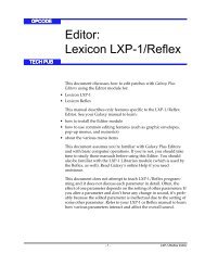
Grounding Variations (<strong>PT</strong> version)<br />
Common Signal Ground<br />
Top Row<br />
Soldering Pads<br />
Chassis Ground<br />
to connect<br />
Individual Grounds to Common Ground<br />
Common Signal Ground<br />
Bottom Row<br />
Jumper Setting for Group, Central & Chassis Common<br />
Common Signal Grounds of<br />
Top and Bottom Row separated<br />
Common Signal Ground Bottom Row<br />
connected to Chassis Ground<br />
Common Signal Ground Top Row<br />
connected to Chassis Ground<br />
Arrangement<br />
Push Terminals<br />
Common Signal Ground Top and Bottom Row<br />
connected to Chassis Ground<br />
edge of PCB<br />
Common Signal Ground of Top and Bottom Row<br />
connected together and separated from Chassis Ground<br />
... Needed Jumper Position for certain Grounding<br />
... Position has no Influence to the Grounding<br />
Grounding Variations<br />
Position of Pin-Header on PCB<br />
Pin Header<br />
NOTE: In standard configuration there is no ground connection between top and bottom row<br />
unless it is provided by an inserted patch cable. If this is required, as in the case of<br />
phantom powered microphone lines, either make an internal connection by individually<br />
wiring the corresponding upper and lower ‘S’ terminals, or if the latter is critical with<br />
respect to possible ground loops make the connection via patch cable instead of using<br />
the normalling feature.<br />
Page 7 of 13
<strong>NPPA</strong>-<strong>TT</strong>-<strong>PT</strong> Instruction Manual<br />
5. Wiring<br />
For access to the terminals remove the top- and bottom-cover with three cross-recessed screws<br />
(M2.5x8) each fixed in a triangle.<br />
Rear front for wiring<br />
Spring loaded push-terminals with gas tight connection enable fast and easy wiring. NO<br />
soldering or fixing with screws is necessary.<br />
Simply insert the stripped wire (6 mm) after pressing down the white key with a screwdriver.<br />
Color coding of terminals: Orange – Tip (signal +)<br />
Black – Ring (signal -)<br />
White – Sleeve (shield)<br />
The terminal will handle solid and stranded wire up to 20AWG (0.5 mm 2 ). Solid wires up to<br />
18AWG (0.75mm 2 ) are possible.<br />
Wiring with spring loaded push terminals (<strong>PT</strong>)<br />
Tip Ring Sleeve<br />
Page 8 of 13
<strong>NPPA</strong>-<strong>TT</strong>-<strong>PT</strong> Instruction Manual<br />
6. Cable retention to the unit<br />
The built in cable retention bar is at the back of the casing. Simply attach the cables with cable<br />
ties to the bar as shown in the photo.<br />
For large and heavy bundles there is an additional strain relief bar <strong>NPPA</strong>-S available. It is<br />
attached to the casing with four screws.<br />
Cable Retention Bar<br />
7. Channel identification<br />
The front panel is equipped with channel identification strips located in the center of the<br />
channels and marked with the channel numbers 1-24 and 25-48 respectively.<br />
Channel identification strips<br />
Labeling strips<br />
For the perfect management of the system and for individual identification according to<br />
customer’s needs there are two large and separate labeling strips, one for the bottom and one<br />
for the top row.<br />
To write on the paper you have to unscrew one of the outer fixing screws of the front panel.<br />
Then pull out the side-stop, the transparent foil and the paper strip itself.<br />
After marking is done assemble the parts in reversed sequence.<br />
Page 9 of 13
<strong>NPPA</strong>-<strong>TT</strong>-<strong>PT</strong> Instruction Manual<br />
Remove labeling strip<br />
Side Stop<br />
NOTE: For easy and perfect marking you can use our designation software “PatchLabel”<br />
which is available on our web site www.neutrik.com free of charge.<br />
Print-Out software “Patch Label”<br />
Page 10 of 13
<strong>NPPA</strong>-<strong>TT</strong>-<strong>PT</strong> Instruction Manual<br />
8. Technical data<br />
8.1 Electrical<br />
Frequency range:<br />
Digital suitability:<br />
Channel separation:<br />
Insulation resistance:<br />
Connector contact resistance:<br />
Switch contact resistance:<br />
Dielectric strength:<br />
DC to > 50 MHz<br />
Digital audio acc. to AES/EBU<br />
> 100 dB @ 10 kHz, 600 Ω terminated<br />
> 40 dB @ 6 MHz , 110 Ω terminated<br />
> 10 9 Ω @ 500 V dc<br />
< 20 mΩ<br />
< 25 mΩ<br />
1000 V dc<br />
7.2 Mechanical<br />
Lifetime:<br />
> 5.000 Insertion / withdrawal cycles<br />
Insertion / Withdrawal force: < 10 N / > 8 N<br />
Cable retention force:<br />
70 N max per cable retention bar<br />
Dimensions (rack mount): 482 mm (W) × 44 mm (H) (19” × 1 U)<br />
Depth: 178 mm (7”)<br />
Weight:<br />
2.9 kg<br />
Temperature range:<br />
30°C to +80°C<br />
7.3 Materials<br />
Jack housing:<br />
Jack contacts:<br />
Casing:<br />
Front Panel:<br />
PA 66 blend<br />
CuSn6 – TRIBOR ® plated (0.2 µm AuCo over 2 µm NiP)<br />
Steel and aluminum, black coated<br />
AlMgSi 0.5 F22<br />
Page 11 of 13
<strong>NPPA</strong>-<strong>TT</strong>-<strong>PT</strong> Instruction Manual<br />
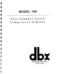
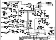
9. Wiring Diagram<br />
Wiring diagram<br />
Page 12 of 13
<strong>NPPA</strong>-<strong>TT</strong>-<strong>PT</strong> Instruction Manual<br />
10. Ordering Information<br />
Patch Panels<br />
Part Number Description Configuration* Wiring Grounding<br />
<strong>NPPA</strong>-<strong>TT</strong>-<strong>PT</strong> 2 x 48 jacks half normalled bottom 288 push terminals individual<br />
<strong>NPPA</strong>-<strong>TT</strong>-<strong>PT</strong>-FN 2 x 48 jacks full normalled 288 push terminals individual<br />
<strong>NPPA</strong>-<strong>TT</strong>-<strong>PT</strong>-HNT 2 x 48 jacks half normalled top row 288 push terminals individual<br />
<strong>NPPA</strong>-<strong>TT</strong>-<strong>PT</strong>-I 2 x 48 jacks isolated 288 push terminals individual<br />
<strong>NPPA</strong>-<strong>TT</strong>-<strong>PT</strong>-P 2 x 48 jacks parallel 288 push terminals individual<br />
* fully loaded jack pairs only<br />
Pre-configured Jack-Pairs<br />
Part Number Description Configuration*<br />
NJ3<strong>TT</strong>A-4-HNB blocks of 2 channels half normalled bottom row cover ident color: clear<br />
NJ3<strong>TT</strong>A-4-HNT blocks of 2 channels half normalled top row cover ident color: yellow<br />
NJ3<strong>TT</strong>A-4-FN blocks of 2 channels full normalled cover ident color: green<br />
NJ3<strong>TT</strong>A-4-P blocks of 2 channels parallel cover ident color: red<br />
NJ3<strong>TT</strong>A-4-I blocks of 2 channels isolated cover ident color: orange<br />
Accessories<br />
<strong>NPPA</strong>-S<br />
NK<strong>TT</strong>*<br />
<strong>NPPA</strong>-NB<br />
Strain Relief bar<br />
Patch cords with NP3<strong>TT</strong>-1 plugs. Available in black, blue, green, red and<br />
yellow. Lenght: 30, 40, 60, 90, 120 cm<br />
Normalling bars for changing the normalling of all 48 channels<br />
Standard supply<br />
The compact <strong>Neutrik</strong> "Easy Patch” <strong>NPPA</strong>-<strong>TT</strong>-<strong>PT</strong> consists of:<br />
• Black coated steel casing with aluminum fittings<br />
• 2 x 48 highly integrated <strong>Neutrik</strong> NJ3<strong>TT</strong>A jacks with gold plated double contacts and specially<br />
designed normalling mechanism (standard: half normalled bottom row)<br />
• Integrated internal pre-wiring with selectable flexible grounding system<br />
• Spring loaded push terminal blocks<br />
• 2 Built–in cable retention bars<br />
• Spare normalling configuration bars<br />
4 Normal 1 : “short”, bridges 5 contacts<br />
8 Normal 2 : “medium”, bridges 6 contacts<br />
4 Normal 3 : “long” , bridges 7 contacts<br />
• 1 Disassembling pliers<br />
• 1 Instruction Manual<br />
Page 13 of 13