Comtrol CC-4500 Compressor & Condenser ... - icemeister.net
Comtrol CC-4500 Compressor & Condenser ... - icemeister.net
Comtrol CC-4500 Compressor & Condenser ... - icemeister.net

Create successful ePaper yourself
Turn your PDF publications into a flip-book with our unique Google optimized e-Paper software.
C O N T E N T S<br />
(Click on items in RED to take you straight to that page in the maual)<br />
1 Introduction . . . . . . . . . . . . . . . . . . . . . . . . . . . . . . . 1-1<br />
General . . . . . . . . . . . . . . . . . . . . . . . . . . . . . . . . . . . . . . . . . . . 1-1<br />
The Front Panel . . . . . . . . . . . . . . . . . . . . . . . . . . . . . . . . . . . . 1-1<br />
Passwords . . . . . . . . . . . . . . . . . . . . . . . . . . . . . . . . . . . . . . . . 1-2<br />
2 Installation . . . . . . . . . . . . . . . . . . . . . . . . . . . . . . . 2-1<br />
3 Programming/Setup . . . . . . . . . . . . . . . . . . . . . . . . 3-1<br />
Setting the Refrigerant Type . . . . . . . . . . . . . . . . . . . . . . . . . . 3-1<br />
Setup Suction #1 & #2 . . . . . . . . . . . . . . . . . . . . . . . . . . . . . . . 3-2<br />
Setup <strong>Condenser</strong> . . . . . . . . . . . . . . . . . . . . . . . . . . . . . . . . . . 3-3<br />
Change Passwords . . . . . . . . . . . . . . . . . . . . . . . . . . . . . . . . . 3-4<br />
Set Date & Time . . . . . . . . . . . . . . . . . . . . . . . . . . . . . . . . . . . . 3-5<br />
Calibration . . . . . . . . . . . . . . . . . . . . . . . . . . . . . . . . . . . . . . . . 3-6<br />
4 Viewing Status . . . . . . . . . . . . . . . . . . . . . . . . . . . 4-1<br />
Status of Suction #1 & #2 . . . . . . . . . . . . . . . . . . . . . . . . . . . . . 4-1<br />
Status of <strong>Condenser</strong> . . . . . . . . . . . . . . . . . . . . . . . . . . . . . . . . . 4-4<br />
5 Changing Setpoints . . . . . . . . . . . . . . . . . . . . . . . 5-1<br />
Suction #1 & #2 Setpoints . . . . . . . . . . . . . . . . . . . . . . . . . . . . . 5-1<br />
<strong>Condenser</strong> Setpoints . . . . . . . . . . . . . . . . . . . . . . . . . . . . . . . . 5-2<br />
6 Alarms . . . . . . . . . . . . . . . . . . . . . . . . . . . . . . . . . . . 6-1<br />
Alarm History Log . . . . . . . . . . . . . . . . . . . . . . . . . . . . . . . . . . . 6-1<br />
Change Alarm Settings . . . . . . . . . . . . . . . . . . . . . . . . . . . . . . . . 6-3<br />
Clear Alarm History Log . . . . . . . . . . . . . . . . . . . . . . . . . . . . . . . 6-4<br />
7 Drawings . . . . . . . . . . . . . . . . . . . . . . . . . . . . . . . . . . . . . . . . 7-1<br />
8 Control Algorithms . . . . . . . . . . . . . . . . . . . . . . . . . . . . . . . 8-1<br />
03/03/02
Chapter 1 - Introduction<br />
General<br />
The <strong>CC</strong>-<strong>4500</strong> <strong>Compressor</strong> & <strong>Condenser</strong> Controller was developed to provide a cost<br />
effective, easy to use electronic controller for all applications that require compressor and<br />
condenser control at a lower cost.<br />
The <strong>CC</strong>-<strong>4500</strong> controller was developed to be fully compatible with Com-Trol I/O boards,<br />
COM-5002 Communications Controller, and MCS-6000 Graphical user interface. While<br />
most systems will provide only the basic compressor and condenser control, they can be<br />
expanded to a fully integrated control system at anytime, if the customer so desires.<br />
The <strong>CC</strong>-<strong>4500</strong> can control up to two suction groups with up to 8 compressors (or<br />
compressors and unloaders) each. It can also control one air-cooled condenser with up to<br />
eight stages. Floating suction control with one case temperature sensor for each suction<br />
group is optional.<br />
The control algorithms are the same as used in the Com-Trol MCS-4000, but the set-up<br />
and operational screens have been customized for the limited application, thus making it<br />
extremely easy to program and use.<br />
The controller is based upon Com-Trol’s MCS-<strong>4500</strong>, with a customized keypad/overlay<br />
and a 4 line by 20 character LCD display. Alarm indications are provided by flashing<br />
LED’s and a buzzer. There are alarm outputs that can be used to drive remote relays for<br />
alarm lights and/or bells. The controller is mounted on a flat panel that fits nicely into a<br />
control panel mounting location.<br />
Alarms are provided for suction pressure, head pressure, phase loss, oil failure, as well as<br />
hardware failure alarms.<br />
Help is built into the controller. Pressing the Help key will bring up information to explain<br />
the particular screen/function you are on.<br />
The Front Panel<br />
The Front Panel contains the 4 line by 20 character display, the alarm LED’s and the<br />
keypad.<br />
03/03/02 Introduction 1-1
Introduction (cont.)<br />
The alarm LED’s will flash in sequence anytime there is an active alarm. A buzzer will also<br />
be activated when an alarm occurs, but it can be silenced, until another alarm occurs, by<br />
pressing the Cancel key.<br />
The keypad consists of twenty keys, the purpose of each key is as follows:<br />
0 to 9 - entry of setpoints.<br />
. - decimal point or : when entering delay times.<br />
- - minus sign for temperature below zero.<br />
Help<br />
- brings up the appropriate help information screen.<br />
Cancel - silences the alarm buzzer or voids the entry of a setting prior to<br />
hitting Enter.<br />
Escape - backs you up one screen/menu.<br />
Enter - secures change/setting or selection and moves to next screen.<br />
fl<br />
- moves down one line or to next page, if at bottom.<br />
› - moves up one line or to previous page, if at top.<br />
fi<br />
- moves to another screen associated with the screen you are on<br />
giving more information.<br />
‹ - returns you from a screen giving additional information.<br />
Passwords<br />
The <strong>CC</strong>-<strong>4500</strong> contains two levels of passwords. The low level starts out as 8888. The high<br />
level starts out at 9999. They can be changed at any time (see Programming/Setup -<br />
Chapter 3). You will be automatically prompted for a password anytime you are performing<br />
a function or entering into an area where changes can be made. The low level password<br />
lets you make setpoint changes. The high level password is required for the Setup<br />
function, to change passwords, and to Clear the alarm History Log.<br />
03/03/02 Introduction 1-2
Chapter 2 - Installation<br />
The installation of the <strong>CC</strong>-<strong>4500</strong> is very simple. The controller is pre-mounted on a flat panel<br />
(part number 45TD270G01). This panel has six (6) #10 screw studs at each corner for<br />
mounting to the control cabi<strong>net</strong> door. Drills holes and place the panel/controller assembly<br />
into position and secure into place with nuts and star washers provided (Chapter 7-1).<br />
Next, mount the power transformer and cable assembly (part number 45TB001G01) on the<br />
back plane. Wire the primary side of the transformer to the appropriate terminals. This<br />
transformer/cable assembly will power the controller and up to two I/O boards. If more<br />
boards are needed, use transformer/cable assembly for controller and use another 5 board<br />
transformer for board power.<br />
Mount the input and output boards, as required for the particular job, to the back plane.<br />
Most jobs will require one to three relay boards, and one input board (AI-8). (Chapter 7-2).<br />
Connect the transformer, I/O boards, and <strong>CC</strong>-<strong>4500</strong> controller together with the pre-wired<br />
cable harness (Chapter 7-2,3).<br />
Set the address switches on the I/O boards as follows:<br />
1 st RO-8 = 0, 2 nd RO-8 = 1, etc. as required.<br />
AI-8 or AI-16 = 0.<br />
The control wiring of the compressors and fans to the relay boards, and the input wiring for<br />
the pressures, temperature, and monitors, will be determined by the set-up of the <strong>CC</strong>-<strong>4500</strong><br />
controller for each application. The controller automatically makes the board and point<br />
assignments, however it will follow the same format each time as follows:<br />
Relays<br />
1. <strong>Compressor</strong> #1 - Suction group #1<br />
2. <strong>Compressor</strong> # 2 or unloader for <strong>Compressor</strong> #1 - Suction group #1<br />
3. <strong>Compressor</strong> #3 or <strong>Compressor</strong> #2, if unloader on #1-Suction grp #1etc.<br />
4. Suction group #2 follows in same manner, if present.<br />
<strong>Condenser</strong> Stage 1 to 8<br />
Digital Inputs<br />
1. Phase Loss<br />
2. Oil Failure #1 (Rack Alarm)<br />
3. Oil Failure #2, if second suction group.<br />
4. Low Refrigerant (optional – DI or AI)<br />
5. Hot Gas DI (optional)<br />
03/03/02 Installation 2-1
Installation (cont.)<br />
Analog Inputs<br />
1. Head Pressure<br />
2. Suction pressure #1<br />
3. Suction pressure #2, if second suction group, or Float #1<br />
4. Float #1<br />
5. Float #2<br />
Example: Single Suction Rack, w/ 3 compressors, 4 fan stages; Use one RO-8, & one AI-<br />
8.<br />
RO-8<br />
AI-8<br />
1. <strong>Compressor</strong> 1 1. Phase Loss*<br />
2. <strong>Compressor</strong> 2 2. Oil Failure #1*<br />
3. <strong>Compressor</strong> 3 3. N/A (would be Oil Fail #2 if used)*<br />
4. <strong>Condenser</strong> Fan Stage 1 4. Low Refrigerant (optional)*<br />
5. <strong>Condenser</strong> Fan Stage 2 5. Hot Gas DI (optional)*<br />
6. <strong>Condenser</strong> Fan Stage 3 6. Head Pressure*<br />
7. <strong>Condenser</strong> Fan Stage 4 7. Suction Pressure #1*<br />
8. spare 8. Float#1(optional)<br />
Note: For the digital inputs on the AI-8 board, the dip switches must be set to 1=ON,<br />
2=OFF. For temp sensors and Pressure Transducers, both are ON.<br />
Also, the jumper at the top of the board must be set to AI/DI any time you have both<br />
digital and analog inputs on the same board.<br />
Example: Dual Suction Rack, w/ 3 compressors each w/ unloader on first compressor, 5<br />
fan stages; Use two RO-8, & one AI-16.<br />
RO-8 R0-8 AI-16<br />
1. <strong>Compressor</strong> 1-1 1. <strong>Condenser</strong> Fan Stage 1 1. Phase Loss*<br />
2. Unloader 1-1 2. <strong>Condenser</strong> Fan Stage 2 2. Oil Failure #1*<br />
3. <strong>Compressor</strong> 2-1 3. <strong>Condenser</strong> Fan Stage 3 3. Oil Failure #2*<br />
4. <strong>Compressor</strong> 3-1 4. <strong>Condenser</strong> Fan Stage 4 4. Low Ref–option*<br />
5. <strong>Compressor</strong> 1-2 5. <strong>Condenser</strong> Fan Stage 5 5. HotGasDI-option*<br />
6. Unloader 1-2 6. Spare 6. Head Press*<br />
7. <strong>Compressor</strong> 2-2 7. Spare 7. SuctionPress #1*<br />
8. <strong>Compressor</strong> 3-2 8. Spare 8. SuctionPress #2<br />
9.Float #1<br />
10. Float #2<br />
11-16 Spare<br />
* Denotes input board points that are “fixed” to those particular features listed. If feature is<br />
not used, do not wire that input point on the board.<br />
03/03/02 Installation 2-2
Chapter 3 - Programming/Setup<br />
Programming or Setup of the <strong>CC</strong>-<strong>4500</strong> has been greatly simplified. The user only has to<br />
specify the type of refrigerant being used; then for each suction group, the suction<br />
temperature or target pressure desired, and the horsepower of each compressor/unloader.<br />
For the <strong>Condenser</strong> specify, the condensing temperature or target pressure desired and the<br />
number of fans/stages. The set-up is then complete. The controller does the rest of the<br />
work: assigns all the inputs and outputs required, sets-up the appropriate alarms, and<br />
provides standardized names to all the inputs & outputs.<br />
The Menu Tree and screens for each operation are show below:<br />
MAIN MENU<br />
→ Status<br />
Setpoints<br />
Alarms<br />
Pressing the fl key 3 times brings you to the Setup selection.<br />
MAIN MENU<br />
Setpoints<br />
Alarms<br />
→ Setup<br />
Press Enter, to bring up the Setup Menu.<br />
SETUP MENU<br />
→ Refrigerant Type<br />
Suction #1<br />
Suction #2<br />
Setting the Refrigerant Type<br />
Pressing Enter with the fi pointing to Refrigerant Type allows you to select the refrigerant<br />
that is being used on this Rack.<br />
REFRIGERANT TYPE<br />
R-404A<br />
Enter 1 to 9<br />
Press Help for List<br />
Press the Help key to get to a list of refrigerants to choose from. The current or default<br />
selection is shown at the upper right, i.e.R404A. The Help screen gives a list of the<br />
refrigerants to choose from as shown below:<br />
1 = R-22<br />
2 = R-409A<br />
3 = R-134A<br />
page 1 of 3<br />
↓↑<br />
03/03/02 Installation 3-1
Programming/Setup (cont.)<br />
Pressing the fl key brings up the next page of the Help Screen, etc. until all Help screens<br />
are viewed. You can back up through the Help screens with the › key. These prompts are<br />
shown at the lower right hand corner.<br />
4 = R-404A (HP62)<br />
5 = R-507 (AZ50)<br />
6 = R-402A (HP80)<br />
page 2 of 3 ↓↑<br />
7 = R-401B<br />
8 = G-125<br />
9 = R-408A<br />
page 3 of 3<br />
↓↑<br />
To return to the screen you came from, press the Escape key. Then type the number, 1 to<br />
9, of the refrigerant that will be used for this Rack. Press the Enter key to make the<br />
selection.<br />
Press the Escape key to return to the Setup Menu.<br />
SETUP MENU<br />
→ Refrigerant Type<br />
Suction #1<br />
Suction #2<br />
Setup Suction #1 & #2<br />
From the Setup Menu, press the fl once to move to Suction #1,<br />
SETUP MENU<br />
Refrigerant Type<br />
→ Suction #1<br />
Suction #2<br />
then press Enter to make the selection.<br />
SETUP SUCTION #1<br />
→Suct Temp -25.0 f<br />
Target PSI 15.0 PSI<br />
Enter value or ↓<br />
You may now type in the desired Suction Temperature, Suct Temp, or press the fl key<br />
once, and type in the desired Target Pressure, Target PSI. These two values are linked by<br />
the selected refrigerant type, so if you change one, the other will change accordingly when<br />
you press the Enter key.<br />
03/03/02 Programming/Setup 3-2
Programming/Setup (cont.)<br />
Press the fl until you get to the next screen. The optional liquid level is entered next.<br />
SETUP SUCTION #1<br />
Liq Lvl Input<br />
→ 2<br />
Enter 0 or 1 or 2<br />
“0” provides no liquid level input; “1” provides a DI input (Float switch); and “2” provides an<br />
analog (AI) input (Hansen). Type in the desired entry, then press Enter. Press the fl until<br />
you get to the next screen. The HP of each compressor and unloader is entered next.<br />
SETUP SUCTION #1<br />
→Compr 1 HP 0.0<br />
Unldr 1 HP 0.0<br />
Enter HP; 0=none<br />
Type in the HP of compressor 1, then press Enter. Make it as accurate as possible. (Note:<br />
you can also enter the MBH capacity, e.g. 36,500 BTU = 36.5 MBH.) If compressor 1 has<br />
an unloader, press the fl key to select the unloader, Unldr. Type in its HP (the amount of<br />
capacity it has control of, i.e. 10HP compressor with 50% unloader, unloader HP = 5). If no<br />
unloader is present, leave HP at 0.0. Press the fl key until the Compr 2 screen appears.<br />
Enter its HP (or MBH) as indicated previously.<br />
SETUP SUCTION #1<br />
→Compr 2 HP 0.0<br />
Unldr 2 HP 0.0<br />
Enter HP; 0=none<br />
Continue, until all compressors and unloaders present have their HP entered. Then by<br />
pressing either Enter with a 0.0 value for HP on a compressor, or pressing the fl key with<br />
0.0 as the compressor HP value, will terminate the set-up process; i.e. these actions<br />
indicate that there are no more compressors. If you make a mistake, simply begin the setup<br />
again, and correct the mistake when you get to that part of the set-up.<br />
If a second suction group, Suction #2, is present, repeat the steps as stated for Suction #1.<br />
03/03/02 Programming/Setup 3-6
Programming/Setup (cont.)<br />
Setup <strong>Condenser</strong><br />
From the SETUP MENU, press the fl until it aligns with <strong>Condenser</strong>,<br />
then press Enter.<br />
SETUP MENU<br />
Suction #1<br />
Suction #2<br />
→<strong>Condenser</strong><br />
SETUP CONDENSER<br />
→Conden. Tmp 80.0f<br />
Target PSI 150.0p<br />
Enter Value or ↓<br />
You may now type in the desired Condensing Temperature, Conden. Tmp, or press the fl<br />
key once, and type in the desired Target Pressure, Target PSI. These two values are linked<br />
by the selected refrigerant type, so if you change one, the other will change accordingly<br />
when you press the Enter key.<br />
Press the fl key until the next screen appears.<br />
SETUP CONDENSER<br />
Total Fans/Stages → 0<br />
Enter Value 0 to 8 ↓<br />
Enter the number of control stages required, 0 to 8, and press Enter.<br />
Press the fl key until the next screen appears.<br />
SETUP CONDENSER<br />
I/O Pack Tight<br />
è 1<br />
Enter 1 or 2<br />
↑↓<br />
This option determines how the I/O (relays) are assigned for the <strong>Condenser</strong> Fans. If “1”,<br />
the pack tight function is disabled – this means that the relays for the condenser will be<br />
assigned to a separate relay board to enable remote location. If “2” the pack tight function<br />
is enabled, placing the condenser relays immediately following the compressor relays.<br />
Press the fl key to return to the SETUP MENU.<br />
03/03/02 Programming/Setup 3-6
Programming/Setup (cont.)<br />
The Setup is now complete. There are two other items in the Setup area; Passwords and<br />
Time Set. They can be changed at any time, but we will cover them now.<br />
Change Passwords<br />
From the SETUP MENU press the fl key until the → is pointing to Passwords.<br />
SETUP MENU<br />
Suction #2<br />
<strong>Condenser</strong><br />
→Passwords<br />
Pressing the Enter key brings up the following screen:<br />
Password Required<br />
Enter Password<br />
→ XXXX<br />
Press Enter<br />
A Level 2 password is required before the passwords can be viewed/changed. The initial<br />
Level 2 password is 9999. Type in the password, and press Enter. If the password was<br />
incorrect, it will indicate so:<br />
Incorrect Password<br />
Enter Password<br />
→ XXXX<br />
Press Enter<br />
Once correctly entered, the following screen will appear:<br />
Change Code Required<br />
Enter Change Code<br />
→ XXXX<br />
Press Enter<br />
The change code is 1843.<br />
If correctly entered, the following screen will appear:<br />
PASSWORDS<br />
→Level 1 8888<br />
Level 2 9999<br />
Select Level 1 or 2 with the fl › keys, type in the new password (numbers), press Enter.<br />
Press Escape to return to the Setup Menu.<br />
03/03/02 Programming/Setup 3-6
Programming/Setup (cont.)<br />
Note: If you forget the passwords, the only way to get them back is to clear the controller<br />
and do the set-up over again. To clear the controller Dip switches 7 & 8 are used in<br />
combination with each other.<br />
Set Date & Time<br />
To set the date & time, from the Setup Menu, press the fl until you get to the Time Set<br />
selection,<br />
then press Enter.<br />
SETUP MENU<br />
<strong>Condenser</strong><br />
Passwords<br />
→Time Set<br />
TIME SET<br />
→02/28/97 15:00:00<br />
← → to select<br />
Enter when done<br />
To set the date, have the selection arrow, → pointing to the date, use the → to move the<br />
underline cursor to the desired item to change, type in the value as appropriate, then press<br />
Enter.<br />
To return to the MAIN MENU press Escape twice.<br />
Calibration<br />
This selection allows an offset to be entered for each transducer for calibration.<br />
To Calibrate the transducers, from the Setup Menu, press the fl until you get to the<br />
Calibrate selection,<br />
SETUP MENU<br />
Passwords<br />
Time Set<br />
→Calibration<br />
then press Enter. The following screen will appear:<br />
SENSOR CALIBRATION<br />
→Head Pressure 0.0<br />
Suction #1 0.0<br />
03/03/02<br />
Suction #2 0.0<br />
Programming/Setup 3-6
Programming/Setup (cont.)<br />
Use the fl› keys to select the desired transducer input, then enter the required<br />
offset/calibration amount, and press Enter. For example, if the transducer reading is 3 PSI<br />
high, you would enter a - 3.0; 3 PSI would be subtracted from the transducer reading before<br />
it was used by the controller. Likewise, if the transducer was reading 2 PSI high, you would<br />
enter 2.0 for the offset so that the controller would add 2 PSI before it used the used the<br />
reading.<br />
NOTE: Make sure your reference gauge is accurate/calibrated before you make any<br />
adjustments to the transducer calibration.<br />
03/03/02 Programming/Setup 3-6
Chapter 4 - Viewing Status<br />
The Status selection on the MAIN MENU leads to screens that show the current operating<br />
status and set points; e.g. what the current suction pressure(s), head pressure, and float<br />
temperatures are (updated every 6 seconds.); which compressors/fan stages are ON/OFF,<br />
etc.<br />
MAIN MENU<br />
→ Status<br />
Setpoints<br />
Alarms<br />
Pressing Enter with the → pointing to Status brings up the following screen:<br />
STATUS MENU<br />
→ Suction #1 Norm Run<br />
Suction #2 Norm Run<br />
<strong>Condenser</strong> Norm Run<br />
The Mode is shown after the name. It indicates the operating status.<br />
The possible conditions indicated here are:<br />
Norm Run - Everything OK.<br />
Hi Head - The compressors have been staged off because the head pressure<br />
rose above the high head setting.<br />
LoSafety - compressors have been cycled off because the suction pressure<br />
dropped below the Low Safety setting.<br />
PhasLoss - the phase loss digital input was closed indicating a phase loss<br />
condition and all compressors are shutdown.<br />
LockRecv - compressors are held off for 60 seconds following a phase loss.<br />
All Off - All compressors or fans are shut-off under normal control.<br />
To view the Status of any item, move the selection arrow, →, with the fl › keys to the<br />
desired item, then press the Enter key.<br />
Status of Suction #1 / #2<br />
Pressing Enter with the → pointing to Suction #1 (or #2) brings up the following screen:<br />
STATUS SUCT #1<br />
Suction 20.0 PSI<br />
Sat. Suct -15.0 f<br />
Connected to 1-1 ↓↑<br />
03/03/02 Viewing Status 4-1
Viewing Status (cont.)<br />
The current suction pressure and its equivalent saturated suction temp are given here, and<br />
updated every 6 seconds. The bottom line shows what board and analog point address the<br />
suction pressure transducer should be connected to, i.e. board 1 - point 1.<br />
Pressing the fl key once will take you to the next status screen for the selected Suction<br />
group.<br />
STATUS SUCT #1<br />
Target PSI 18.0 PSI<br />
Sat Tgt Tmp -17.0 f<br />
↓↑<br />
The current Target pressure and it’s equivalent saturated suction temperature are shown<br />
here.<br />
Note: The Target pressure may be different from the target set point, if floating suction is<br />
being used. The float up is limited to 5 PSI, and the float down is limited to 3 PSI.<br />
Pressing the fl key once will take you to the next status screen for the selected Suction<br />
group.<br />
STATUS SUCT #1<br />
Head PSI 150.0 PSI<br />
Sat Cnd Tmp 85.0 f<br />
Connected to 1-2 ↓↑<br />
The current head pressure and the equivalent saturated condensing temperature are shown<br />
here, along with the board and analog point assignment for the head pressure transducer.<br />
Pressing the fl key once will take you to the next status screen for the selected Suction<br />
group.<br />
STATUS SUCT #1<br />
Float Temp -10.5 f<br />
Float Target -10.0 f<br />
Connected to 1-3 ↓↑<br />
The current float temperature and float target temperature are shown here, along with the<br />
board and analog point assignment for the float temperature sensor.<br />
Note: If the Float Target is set above 75 f, the floating feature is disabled (refer to Setpoints<br />
Chapter 5).<br />
03/03/02 Viewing Status 4-2
Viewing Status (cont.)<br />
Pressing the fl key once will take you to the next status screen for the selected Suction<br />
group.<br />
STATUS SUCT #1<br />
Load 89.0%<br />
Reaction Speed 5<br />
↓↑<br />
Pressing the fl key once will take you to the next status screen for the selected Suction<br />
group.<br />
STATUS SUCT #1<br />
Liq Level 25.0<br />
Connected to 1-4<br />
↓↑<br />
The Liquid Level monitor status is shown here, along with its board and point assignment<br />
address. This can either be an analog or digital value (On/Off) depending upon the Setup<br />
Option selected.<br />
Pressing the fl key once will take you to the next status screen for the selected Suction<br />
group.<br />
STATUS SUCT #1<br />
Compr #1 ON<br />
Connected to 1-1<br />
↓↑→<br />
The requested control status, ON/OFF of the first compressor is shown here, along with its<br />
board and relay point assignment address.<br />
Pressing a fi key allows you to view the runtime information for this relay (compressor #1):<br />
Compr #1 ON<br />
Runtime & Cycles<br />
13:00 95 23:10 154<br />
↓↑←<br />
The runtime and cycle count for today, starting from midnight, and the runtime and cycle<br />
count for yesterday are shown here.<br />
Pressing the ‹ key will return you to the screen you came from. Then press the<br />
fl key, to move on to the status of the next compressor, or unloader if the compressor is<br />
equipped with one.<br />
03/03/02 Viewing Status 4-5
Viewing Status (cont.)<br />
If the compressor was programmed with an unloader, it’s status will be shown next.<br />
Note: If an unloader is ON, it means that the compressor has its full capacity available; if the<br />
unloader is OFF, the compressor is running unloaded.<br />
Once you reach the last compressor/unloader screen, you will return to Status Menu by<br />
pressing the fl key, or press Escape at anytime.<br />
Status of <strong>Condenser</strong><br />
To view the Status of the <strong>Condenser</strong>, press the fl key until it points to <strong>Condenser</strong>.<br />
STATUS MENU<br />
Suction #1<br />
Suction #2<br />
→<strong>Condenser</strong><br />
Press Enter to go to its first status screen.<br />
STATUS CONDENSER<br />
Head PSI 150.0PSI<br />
Sat Cnd Tmp 85.0f<br />
Connected to 1-2 ↓↑<br />
The current Head pressure and the equivalent saturated condensing temperature for the<br />
programmed refrigerant are shown here, along with the board and analog point assignment<br />
for the head pressure transducer.<br />
Pressing the fl key once will take you to the next status screen for the <strong>Condenser</strong>.<br />
STATUS CONDENSER<br />
Target PSI 105.0 PSI<br />
Sat Tgt Tmp 60.0 f<br />
Stage Diff. 5.0 PSI↓↑<br />
The current Target pressure and it’s equivalent saturated discharge/head temperature, and<br />
the staging differential are shown here.<br />
Pressing the fl key once will take you to the next status screen for the <strong>Condenser</strong>.<br />
STATUS CONDENSER<br />
Fan/Stage #1 ON<br />
Connected to 2-1<br />
↓↑→<br />
03/03/02 Viewing Status 4-5
Viewing Status (cont.)<br />
The requested control status, ON/OFF of the first Fan/Stage is shown here, along with its<br />
board and relay point assignment address.<br />
Pressing a fi key allows you to view the runtime information for this relay (Fan/Stage #1):<br />
Fan/Stage #1 ON<br />
Runtime & Cycles<br />
13:00 95 23:10 154<br />
↓↑←<br />
The runtime and cycle count for today, starting from midnight, and the runtime and cycle<br />
count for yesterday are shown here.<br />
Pressing the ‹ key will return you to the screen you came from. Then press the<br />
fl key, to move on to the status of the next <strong>Condenser</strong> Fan/Stage.<br />
When you have viewed all Fan stages you will return to Status Menu by pressing the fl key,<br />
or press Enter at this screen.<br />
03/03/02 Viewing Status 4-5
Chapter 5 - Changing Setpoints<br />
The Setpoints selection from the MAIN allows you to access all the control settings for fine<br />
tuning. Once the ERC is SETUP and tuned, the need for Setpoint changes should be<br />
minimal, and you should always make sure that something else is not the problem before<br />
you change any setpoint.<br />
From the Main /menu use the fl key to move to the Setpoints selection,<br />
MAIN MENU<br />
Status<br />
→Setpoints<br />
Alarms<br />
then press Enter to bring up the SETPOINTS MENU.<br />
SETPOINTS MENU<br />
→Suction #1<br />
Suction #2<br />
<strong>Condenser</strong><br />
Use the fl› keys to select the desired item and then press Enter.<br />
Suction #1  Setpoints<br />
The Suction temperature or Target pressure may be altered on the first screen.<br />
Setpoints Suction #1<br />
→Suct Temp -25.0f<br />
Target PSI 18.0PSI<br />
Enter new value ↓<br />
<strong>Condenser</strong><br />
Use the fl› keys to select the desired entry, type in the new value, and press Enter.<br />
Note: The Suction temp and the Target PSI are linked by the refrigerant type selected.<br />
Thus, if you change one, the other will change accordingly.<br />
Press the fl to move on to the next setpoint screen, or press Escape to return to the<br />
Setpoints Menu.<br />
Setpoints Suction #1<br />
→Low Safety 1.0PSI<br />
Head Safety 325.0PSI<br />
Enter new value ↓↑<br />
<strong>Condenser</strong><br />
Use the fl› keys to select the desired entry, type in the new value, and press Enter.<br />
03/03/02 Changing Setpoints 5-1
Changing Setpoints (cont.)<br />
The Low Safety sets a suction pressure level below which compressors will be staged off at<br />
6 second intervals, to try and bring the suction pressure back above this level; it overrides<br />
the normal control algorithm.<br />
The Head Safety sets a pressure above which the compressors will be staged off to try and<br />
drop the head pressure below the setting; it overrides the normal control algorithm.<br />
Press the fl to move on to the next setpoint screen, or press Escape to return to the<br />
Setpoints Menu.<br />
Setpoints Suction #1<br />
→Reaction Speed 5<br />
Fast-123456789-Slow<br />
Enter 1 to 9<br />
<strong>Condenser</strong><br />
This screen allows you to change the Reaction Speed. This number determines how fast or<br />
slow the controller reacts to pressure changes, and thus has an effect on the cycling rate of<br />
the compressors to maintain the Target. Entering a larger number slows down the reaction<br />
speed. Review the Runtime and Cycles data (See Viewing Status - Chapter 4) to<br />
determine if this number needs adjusting; normally you want to try and keep your daily cycle<br />
rate below 200.<br />
Type in the reaction speed number desired and press Enter.<br />
Press the fl to move on to the next setpoint screen, or press Escape to return to the<br />
Setpoints Menu.<br />
↓↑<br />
Setpoints Suction #1<br />
→Float Temp 80.0f<br />
75 or more disables<br />
Enter new value<br />
<strong>Condenser</strong><br />
↓↑<br />
If floating suction is desired, type in the desired Float temperature and press Enter. Note:<br />
any value entered that is greater than 75 will disable the floating suction feature.<br />
This completes the Setpoints for Suction #1 and Suction #2.<br />
Press the fl or Escape to return to the Setpoints Menu.<br />
<strong>Condenser</strong> Setpoints<br />
Use the fl› keys to select the <strong>Condenser</strong> and then press Enter.<br />
SETPOINTS MENU<br />
Suction #1<br />
Suction #2<br />
→<strong>Condenser</strong><br />
03/03/02 Changing Setpoints 5-2
Changing Setpoints (cont.)<br />
The Condensing temperature or Target pressure may be altered on the first screen.<br />
Setpoints <strong>Condenser</strong><br />
→Cond. Temp 60.0f<br />
Target PSI 105.0PSI<br />
Enter new value <strong>Condenser</strong><br />
Use the fl› keys to select the desired entry, type in the new value, and press Enter.<br />
Note: The Condensing temp and the Target PSI are linked by the refrigerant type selected.<br />
Thus, if you change one, the other will change accordingly.<br />
Press the fl to move on to the next setpoint screen, or press Escape to return to the<br />
Setpoints Menu.<br />
Setpoints <strong>Condenser</strong><br />
→Stage Diff 10.0 PSI<br />
Hi Safety 325.0 PSI<br />
Enter new value ↓↑<br />
<strong>Condenser</strong><br />
Use the fl› keys to select the desired entry, type in the new value, and press Enter.<br />
The Stage Diff. sets the differential between stages. If the Target PSI is 105 PSI, with the<br />
Stage Diff. Set to 10 PSI, the first fan would turn On at 105 and Off at 95, the second fan<br />
stage would turn on at 115 PSI and off at 105 PSI, etc.<br />
The High Safety sets the pressure at which the fans will be staged on at 6 second intervals<br />
to try and lower the head pressure back the setting; this overrides the normal control<br />
algorithm/strategy.<br />
This completes the Setpoints for the <strong>Condenser</strong>.<br />
Press the fl press Escape to return to the Setpoints Menu.<br />
03/03/02 Changing Setpoints 5-3
Chapter 6 - Alarms<br />
The Alarms section of the controller provides the user with a list of the last 40 occurrences<br />
and provides access to change the alarm setpoints and to clear the alarm log.<br />
From the Main /menu use the fl key to move to the Alarms selection,<br />
MAIN MENU<br />
Status<br />
Setpoints<br />
→Alarms<br />
↓↑<br />
then press Enter to bring up the ALARMS MENU.<br />
ALARMS MENU<br />
→History Log<br />
Change Settings<br />
Clear Log ↓↑<br />
Use the fl› keys to select the desired item and then press Enter.<br />
Alarm History Log<br />
The History Log contains a list of the last 40 alarms. The newest alarm is the first viewed.<br />
The oldest/40th alarm is pushed off the list when the next alarm comes in.<br />
Pressing Enter with the selection arrow, →, pointing to History Log brings up the following<br />
screen.<br />
Compr LT #01 1<br />
Suctn In Alm<br />
High Suct 50.0<br />
02/28/97 11:46 ↓↑→<br />
The control task that the alarm is associated with is given on the 1 st line. This could be<br />
Compr LT #01 (Suction #1), or Compr MT #02 (Suction #2), or Fan Group #01<br />
(<strong>Condenser</strong>). The number of the alarm, 1 to 40, is shown at the upper right.<br />
The point/input associated with the alarm (Suct) and alarm status (In Alarm, Timing, Clear)<br />
is shown on the second line.<br />
The alarm type (High Suct) and value (50.0) when the alarm occurred is shown on the third<br />
line.<br />
The date and time stamp when the alarm occurred is given on the bottom line.<br />
03/03/02 Alarms 6-1
Alarms (cont.)<br />
By pressing the fi key, you can view a screen which shows when this alarm cleared; see<br />
example below.<br />
Compr LT #01 1<br />
High Suct<br />
Cleared at<br />
02/28/97 11:50 ←<br />
Press the ‹ key to return to the viewed alarm. Then press the fl key to view the next<br />
alarm, or press Escape to return to the ALARM MENU. Pressing the period, “. “, will return<br />
you to the number 1, newest, alarm.<br />
The alarm shown will depend on the last one that has occurred. The possible alarms are:<br />
High Suct - the suction pressure has been above the high suction alarm setting for<br />
the delay time.<br />
Low Suct - the suction pressure has been below the low suction alarm setting for the<br />
delay time<br />
High Head - the head pressure has been above the high head alarm setting for the<br />
delay time.<br />
Low Head - the head pressure has been below the low head alarm setting for the<br />
delay time.<br />
Oil Fail - the digital input for the oil failure alarm has been closed for the delay time.<br />
Phase Loss - the digital input for the phase loss alarm has been closed for the<br />
delay time; compressors will be shutdown.<br />
Lost Relay - a relay board is not communicating with the controller.<br />
Lost Analog - an analog input board is not communicating with the controller.<br />
Lost Digitl - a digital input board is not communicating with the controller.<br />
Low Gas - indicates low refrigerant charge.<br />
03/03/02 Alarms 6-2
Alarms (cont.)<br />
Open - a pressure transducer or temp sensor has gone open.<br />
Short - a pressure transducer or temperature sensor has been shorted.<br />
Power Up - the controller has regained power.<br />
Power Down - the controller lost power.<br />
Change Alarm Settings<br />
Each alarm is given default setting when the controller is setup. Some fine tuning may be<br />
required for the specific installation. The Change Settings selection on the ALARM MENU<br />
provides access to all the alarm settings.<br />
ALARMS MENU<br />
History Log<br />
→Change Settings<br />
Clear Log ↓↑<br />
Select Change Settings and press Enter.<br />
The first alarm will be displayed. All the alarms are structured the same an are listed one<br />
after the other. Use the fl › keys to get to the alarm you want and to select the setting you<br />
want to change. An example alarm is shown below.<br />
Compr LT #01<br />
High Suct Value<br />
→ Setting 50.0<br />
Delay 00:10↓↑<br />
The control task that the alarm is associated with is given on the 1 st line. This could be<br />
Compr LT #01 (Suction #1), or Compr MT #02 (Suction #2), or Fan Group #01<br />
(<strong>Condenser</strong>).<br />
The alarm type (High Suct) is shown of the second line.<br />
The setting (50.0) and delay time (00:10 - hours: minutes) is shown on the third line and<br />
fourth lines respectively. The delay time is the amount of time you want to wait after the<br />
alarm setting has been reached before the alarm is activated.<br />
To change the setting or delay time, select it by using the fl › keys to place the → on the<br />
item line, type in the new value (use the . for the : ), and press Enter. Use the fl › keys to<br />
select another alarm or press Escape to return to the<br />
ALARMS MENU.<br />
03/03/02 Alarms 6-3
Alarms (cont.)<br />
Clear Alarm History Log<br />
The alarm History Log may be cleared at anytime. The high level password is required.<br />
The alarm history log can provide diagnostic information, so it should not be cleared<br />
casually.<br />
Select the Clear Log item on the ALARMS MENU,<br />
ALARMS MENU<br />
History Log<br />
Change Settings<br />
→Clear Log ↓↑<br />
then press Enter. The password entry screen will pop-up.<br />
Password Required<br />
Enter Password<br />
XXXX<br />
Press Enter<br />
Type in the high level password, and press Enter. If a correct password is entered, the log<br />
will be cleared. If an incorrect password is entered, you will be re-prompted to try and enter<br />
it again. If unsuccessful, you will be returned to the ALARM MENU, and the log will not have<br />
been cleared.<br />
03/03/02 Alarms 6-4
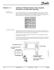
Chapter 7 - Drawings<br />
<strong>CC</strong>-<strong>4500</strong> COMPRESSOR CONDENSER CONTROLLER<br />
CONTROLLER ASSEMBLY<br />
MCS-<strong>4500</strong><br />
processor board<br />
Global Bus - remote<br />
communications option<br />
Power Supply/<br />
Local Alarm Bd.<br />
Local Alarm<br />
outputs<br />
Local Bus -connects<br />
to I/O boards.<br />
Power<br />
Mounting Plate<br />
Mounting Studssix<br />
@ 10X32<br />
03/03/02 Drawings 7-1
<strong>CC</strong>-<strong>4500</strong> CONTROLLER<br />
TYPICAL SYSTEM LAYOUT<br />
<strong>CC</strong>-<strong>4500</strong> Assembly<br />
AI-8<br />
Analog Input board<br />
RO-8<br />
Relay Output Board;<br />
as required<br />
Transformer;<br />
pre-wired to<br />
harness<br />
Power Cable;<br />
pre-wired harness<br />
Local Bus Cable;<br />
pre-wired harness<br />
Power & Local<br />
Bus Jumper Cables<br />
Pre-wired<br />
RO-8<br />
Relay Output Board<br />
03/03/02 Drawings 7-2
<strong>CC</strong>-<strong>4500</strong> CONTROLLER<br />
WIRING DETAILS<br />
Global Bus<br />
+ C - + C -<br />
Local Bus to I/O<br />
L +12 B<br />
CT +12<br />
Local Alarm<br />
Outputs; light &<br />
buzzer or bell;<br />
optional<br />
I/O Board Power <strong>CC</strong>-<strong>4500</strong> Power<br />
Global Bus to<br />
COM-5002 or<br />
MCS-6000;<br />
optional<br />
+12 CT +12<br />
- C +<br />
+12 C.T. +12<br />
Orange<br />
120 vac - White/Black<br />
208 vac - White/Red<br />
240 vac - White/Orange<br />
03/03/02 Drawings 7-3
<strong>CC</strong>-<strong>4500</strong> CONTROLLER<br />
HARDWARE DETAILS<br />
Dip Switch<br />
Global Com<br />
Chip<br />
Empty socket<br />
Local Com Chip<br />
ON<br />
8 7 6 5 4 3 2 1<br />
Dipswitch Notes:<br />
Switch 8 must be UP(Off) to select proper local com port.<br />
Switches 1 thru 5 are only used if remote communications are present to set the address of the controller.<br />
Switch 6 is only used if remote communications are present - ON for Com-5002, Off for MCS-6000.<br />
Switch 7 is used in combination with switch 8 to clear the memory of the controller.<br />
03/03/02 Drawings 7-4
Chapter 8 - Control Algorithms<br />
<strong>Compressor</strong> Control<br />
The compressors are controlled with a PID algorithm. When initially set-up, the HP or<br />
MBtuh capacity of each compressor/unloader is entered. The system then assembles all<br />
possible combinations of capacity and stores them in a table. Combinations with a<br />
difference of less than 2% between them are eliminated.<br />
The suction pressure is compared to the current Target pressure every six seconds. The<br />
Target pressure can float up or down between specified limits (+5 & -3 PSI), based upon<br />
the float temperature being above or below target. The difference from target is multiplied<br />
by a proportional constant. KP and the differences over the last 5 periods (30 seconds) are<br />
multiplied by the integral constant, KI, and averaged. These results are added together and<br />
divided by the change in suction pressure from one period to the next multiplied by the<br />
derivative constant, KD. The <strong>net</strong> result of these three factors represents the current Load<br />
and is expressed in percent. The algorithm compares this value to the steps of capacity<br />
available (in percentage) and moves up or down in the capacity table accordingly. When a<br />
change in capacity is required, the algorithm only allows a change of one step every 18<br />
seconds to reduce hunting/overshoot.<br />
The 3 constants (KP, KI, KD) are contained in a table, with each group of three being<br />
represented by a single number called Reaction Speed (1 - 9); the response of the<br />
algorithm can be slowed down by increasing the Reaction Speed setting or speeded up by<br />
reducing it.<br />
Safeties are built-in for low suction and high head. If the low suction setting is reached,<br />
compressors are sequenced off every 6 seconds, until all are off or the low suction condition<br />
no longer exists. If the high head setting is reached, compressors are sequenced off every<br />
6 seconds, until the head pressure falls below the high head setting minus a specified<br />
differential, or all are off. Alarms are also created with these events.<br />
If a Phase Loss condition occurs (phase loss digital input closes), all compressors are<br />
shutdown within 12 seconds. When normal power returns, the compressors are held off an<br />
additional 60 seconds, called Lock Recovery, to make sure the power is going to stay up,<br />
before they are sequenced back on.<br />
The Oil failure or Rack Alarm, indicates that the contacts, that the digital input is connected<br />
to, have closed, and an alarm activated - no control actions are taken. The exact meaning<br />
of this alarm is determined by the OEM’s wiring/design.<br />
03/03/02 Algorithms 8-1
Control Algorithms (cont.)<br />
<strong>Condenser</strong> Control<br />
The <strong>Condenser</strong> Control is very similar to the compressor control. It also uses a PID<br />
algorithm. When the number of stages is specified, it is assumed that each stage has equal<br />
capacity, and the step table that is built is a straight sequence with each having a capacity<br />
of 100% divided by the number of stages.<br />
The head pressure is compared to the current target pressure every six seconds.<br />
The difference from target is multiplied by a proportional constant, KP, and the differences<br />
over the last 5 periods (30 sec.) are multiplied by the integral constant, KI, and averaged.<br />
These results are added to the change in head pressure from one period to the next<br />
multiplied by the derivative constant, KD. The <strong>net</strong> result of these three factors represents the<br />
current Load and is expressed in percent. The algorithm compares this value to the steps<br />
of capacity available (in percentage) and moves up or down in the capacity table<br />
accordingly. When a change in capacity is required, the algorithm only allows a change of<br />
one step every 30 seconds to reduce hunting/overshoot.<br />
The 3 constants (KP, KI, KD) are contained in a table, with each group of three being<br />
represented by a single number called Reaction Speed (1 - 9); the response of the<br />
algorithm can be slowed down by increasing the Reaction Speed setting or speeded up by<br />
reducing it.<br />
Safeties are built-in for high head. If the high safety setting is reached, fans are staged ON<br />
every 6 seconds, overriding the PID algorithm, until all are ON or the head pressure drops<br />
below the high safety setting. Alarms are also created with these events.<br />
03/03/02 Algorithm 8-2