Ranco Eco-Cool E71R/E72R Temperature and ... - icemeister.net
Ranco Eco-Cool E71R/E72R Temperature and ... - icemeister.net
Ranco Eco-Cool E71R/E72R Temperature and ... - icemeister.net
- No tags were found...

Create successful ePaper yourself
Turn your PDF publications into a flip-book with our unique Google optimized e-Paper software.
DRAFT VERSION<strong>Temperature</strong> <strong>and</strong>Defrost ControllerType E7354-00027-001 Rev. D<strong>Eco</strong><strong>Cool</strong> Controller <strong>and</strong> Configuration SoftwareInstallation <strong>and</strong> ConfigurationType E7 <strong>Eco</strong><strong>Cool</strong> Electronic <strong>Temperature</strong> <strong>and</strong> Defrost Controllers©2008 Invensys Controls All rights reserved.1
DRAFT VERSIONCONTENTS1 How to use this manual. . . . . . . . . . . . . . . . . . . . . . . . . . . . . . . . . . . . . . . . . . . . . . . . . . . . . . . . . . . . . . . . . . . . . . 42 Introduction . . . . . . . . . . . . . . . . . . . . . . . . . . . . . . . . . . . . . . . . . . . . . . . . . . . . . . . . . . . . . . . . . . . . . . . . . . . . . . . 43 <strong>E71R</strong> <strong>and</strong> <strong>E72R</strong> controllers . . . . . . . . . . . . . . . . . . . . . . . . . . . . . . . . . . . . . . . . . . . . . . . . . . . . . . . . . . . . . . . . . . . 43.1 Overview . . . . . . . . . . . . . . . . . . . . . . . . . . . . . . . . . . . . . . . . . . . . . . . . . . . . . . . . . . . . . . . . . . . . . . . . . . . . . . . 44 Installation . . . . . . . . . . . . . . . . . . . . . . . . . . . . . . . . . . . . . . . . . . . . . . . . . . . . . . . . . . . . . . . . . . . . . . . . . . . . . . . . 54.1 Installing the controller . . . . . . . . . . . . . . . . . . . . . . . . . . . . . . . . . . . . . . . . . . . . . . . . . . . . . . . . . . . . . . . . . . . . 54.1.1 Wiring the controller . . . . . . . . . . . . . . . . . . . . . . . . . . . . . . . . . . . . . . . . . . . . . . . . . . . . . . . . . . . . . . . . 64.2 Mounting the display . . . . . . . . . . . . . . . . . . . . . . . . . . . . . . . . . . . . . . . . . . . . . . . . . . . . . . . . . . . . . . . . . . . . . . 74.3 Wiring the display . . . . . . . . . . . . . . . . . . . . . . . . . . . . . . . . . . . . . . . . . . . . . . . . . . . . . . . . . . . . . . . . . . . . . . . . 75 Functions <strong>and</strong> features . . . . . . . . . . . . . . . . . . . . . . . . . . . . . . . . . . . . . . . . . . . . . . . . . . . . . . . . . . . . . . . . . . . . . . 75.1.1 User control . . . . . . . . . . . . . . . . . . . . . . . . . . . . . . . . . . . . . . . . . . . . . . . . . . . . . . . . . . . . . . . . . . . . . . 75.1.2 Control mode . . . . . . . . . . . . . . . . . . . . . . . . . . . . . . . . . . . . . . . . . . . . . . . . . . . . . . . . . . . . . . . . . . . . . 75.1.3 Status indications . . . . . . . . . . . . . . . . . . . . . . . . . . . . . . . . . . . . . . . . . . . . . . . . . . . . . . . . . . . . . . . . . . 95.1.4 Defrost control . . . . . . . . . . . . . . . . . . . . . . . . . . . . . . . . . . . . . . . . . . . . . . . . . . . . . . . . . . . . . . . . . . . . 95.1.5 Alarms . . . . . . . . . . . . . . . . . . . . . . . . . . . . . . . . . . . . . . . . . . . . . . . . . . . . . . . . . . . . . . . . . . . . . . . . . 115.1.5.1 <strong>Temperature</strong> . . . . . . . . . . . . . . . . . . . . . . . . . . . . . . . . . . . . . . . . . . . . . . . . . . . . . . . . . . . . . . . 115.1.5.2 Faults . . . . . . . . . . . . . . . . . . . . . . . . . . . . . . . . . . . . . . . . . . . . . . . . . . . . . . . . . . . . . . . . . . . . 125.1.6 Display . . . . . . . . . . . . . . . . . . . . . . . . . . . . . . . . . . . . . . . . . . . . . . . . . . . . . . . . . . . . . . . . . . . . . . . . . 135.1.7 Sensor failure mode . . . . . . . . . . . . . . . . . . . . . . . . . . . . . . . . . . . . . . . . . . . . . . . . . . . . . . . . . . . . . . . 136 Device <strong>and</strong> software configuration. . . . . . . . . . . . . . . . . . . . . . . . . . . . . . . . . . . . . . . . . . . . . . . . . . . . . . . . . . . . 146.1 Controller <strong>and</strong> interface box. . . . . . . . . . . . . . . . . . . . . . . . . . . . . . . . . . . . . . . . . . . . . . . . . . . . . . . . . . . . . . . . 146.1.1 Interface box overview . . . . . . . . . . . . . . . . . . . . . . . . . . . . . . . . . . . . . . . . . . . . . . . . . . . . . . . . . . . . . 146.1.2 Connect the interface box to the computer <strong>and</strong> <strong>E71R</strong> or <strong>E72R</strong> controller. . . . . . . . . . . . . . . . . . . . . . . . 146.2 <strong>Eco</strong><strong>Cool</strong> configuration software . . . . . . . . . . . . . . . . . . . . . . . . . . . . . . . . . . . . . . . . . . . . . . . . . . . . . . . . . . . . . 156.2.1 Minimum computer requirements . . . . . . . . . . . . . . . . . . . . . . . . . . . . . . . . . . . . . . . . . . . . . . . . . . . . . 156.2.2 Software overview . . . . . . . . . . . . . . . . . . . . . . . . . . . . . . . . . . . . . . . . . . . . . . . . . . . . . . . . . . . . . . . . 156.2.3 Install <strong>and</strong> start <strong>Eco</strong><strong>Cool</strong> configuration software . . . . . . . . . . . . . . . . . . . . . . . . . . . . . . . . . . . . . . . . . . 156.2.4 Uninstalling <strong>Eco</strong><strong>Cool</strong> configuration software . . . . . . . . . . . . . . . . . . . . . . . . . . . . . . . . . . . . . . . . . . . . . 156.2.5 Tabbed configuration parameters . . . . . . . . . . . . . . . . . . . . . . . . . . . . . . . . . . . . . . . . . . . . . . . . . . . . . 156.2.5.1 Configuration . . . . . . . . . . . . . . . . . . . . . . . . . . . . . . . . . . . . . . . . . . . . . . . . . . . . . . . . . . . . . . 166.2.5.2 Setpoints . . . . . . . . . . . . . . . . . . . . . . . . . . . . . . . . . . . . . . . . . . . . . . . . . . . . . . . . . . . . . . . . . 176.2.5.3 Defrost . . . . . . . . . . . . . . . . . . . . . . . . . . . . . . . . . . . . . . . . . . . . . . . . . . . . . . . . . . . . . . . . . . . 186.2.5.4 Alarm . . . . . . . . . . . . . . . . . . . . . . . . . . . . . . . . . . . . . . . . . . . . . . . . . . . . . . . . . . . . . . . . . . . . 196.2.5.5 Compressor . . . . . . . . . . . . . . . . . . . . . . . . . . . . . . . . . . . . . . . . . . . . . . . . . . . . . . . . . . . . . . . 206.2.5.6 Fault . . . . . . . . . . . . . . . . . . . . . . . . . . . . . . . . . . . . . . . . . . . . . . . . . . . . . . . . . . . . . . . . . . . . . 216.2.5.7 Display . . . . . . . . . . . . . . . . . . . . . . . . . . . . . . . . . . . . . . . . . . . . . . . . . . . . . . . . . . . . . . . . . . . 226.2.5.8 Fan. . . . . . . . . . . . . . . . . . . . . . . . . . . . . . . . . . . . . . . . . . . . . . . . . . . . . . . . . . . . . . . . . . . . . . 23Type E7 <strong>Eco</strong><strong>Cool</strong> Electronic <strong>Temperature</strong> <strong>and</strong> Defrost Controllers©2008 Invensys Controls All rights reserved.2
<strong>and</strong> opening configuration files . . . . . . . . . . . . . . . . . . . . . . . . . . . . . . . . . . . . . . . . . . . . . . . . . 236.2.7 Transferring configuration files . . . . . . . . . . . . . . . . . . . . . . . . . . . . . . . . . . . . . . . . . . . . . . . . . . . . . . . 246.2.7.1 Downloading a configuration file to a controller from <strong>Eco</strong><strong>Cool</strong> configuration software: . . . . . . . 246.2.7.2 Uploading a configuration file from a controller to <strong>Eco</strong><strong>Cool</strong> configuration software: . . . . . . . . . 246.2.8 Transferring firmware between <strong>Eco</strong><strong>Cool</strong> configuration software <strong>and</strong> a controller. . . . . . . . . . . . . . . . . . 256.2.8.1 Installing firmware on a controller using <strong>Eco</strong><strong>Cool</strong> configuration software:. . . . . . . . . . . . . . . . . 256.2.8.2 Uploading firmware from a controller:. . . . . . . . . . . . . . . . . . . . . . . . . . . . . . . . . . . . . . . . . . . . 256.2.9 Generating reports . . . . . . . . . . . . . . . . . . . . . . . . . . . . . . . . . . . . . . . . . . . . . . . . . . . . . . . . . . . . . . . . 256.2.10 Restoring default values . . . . . . . . . . . . . . . . . . . . . . . . . . . . . . . . . . . . . . . . . . . . . . . . . . . . . . . . . . . . 266.3 Copy card . . . . . . . . . . . . . . . . . . . . . . . . . . . . . . . . . . . . . . . . . . . . . . . . . . . . . . . . . . . . . . . . . . . . . . . . . . . . . 266.3.1 Transferring firmware between a copy card <strong>and</strong> <strong>Eco</strong><strong>Cool</strong> configuration software . . . . . . . . . . . . . . . . . 266.3.2 Downloading a configuration from <strong>Eco</strong><strong>Cool</strong> configuration software into a copy card . . . . . . . . . . . . . . . 276.3.3 Uploading a configuration from a copy card into <strong>Eco</strong><strong>Cool</strong> configuration software . . . . . . . . . . . . . . . . . 276.3.4 Installing firmware or a configuration file into a controller from a copy card . . . . . . . . . . . . . . . . . . . . . 277 Troubleshooting . . . . . . . . . . . . . . . . . . . . . . . . . . . . . . . . . . . . . . . . . . . . . . . . . . . . . . . . . . . . . . . . . . . . . . . . . . . 308 Technical specifications . . . . . . . . . . . . . . . . . . . . . . . . . . . . . . . . . . . . . . . . . . . . . . . . . . . . . . . . . . . . . . . . . . . . 318.1 Electrical rating . . . . . . . . . . . . . . . . . . . . . . . . . . . . . . . . . . . . . . . . . . . . . . . . . . . . . . . . . . . . . . . . . . . . . . . . . 318.2 <strong>Temperature</strong> control range . . . . . . . . . . . . . . . . . . . . . . . . . . . . . . . . . . . . . . . . . . . . . . . . . . . . . . . . . . . . . . . . 318.3 Accuracy . . . . . . . . . . . . . . . . . . . . . . . . . . . . . . . . . . . . . . . . . . . . . . . . . . . . . . . . . . . . . . . . . . . . . . . . . . . . . . 318.4 Terminations . . . . . . . . . . . . . . . . . . . . . . . . . . . . . . . . . . . . . . . . . . . . . . . . . . . . . . . . . . . . . . . . . . . . . . . . . . . 318.5 Environmental requirements . . . . . . . . . . . . . . . . . . . . . . . . . . . . . . . . . . . . . . . . . . . . . . . . . . . . . . . . . . . . . . . 318.6 Electromag<strong>net</strong>ic compatibility (EMC) . . . . . . . . . . . . . . . . . . . . . . . . . . . . . . . . . . . . . . . . . . . . . . . . . . . . . . . . . 318.7 Certifications . . . . . . . . . . . . . . . . . . . . . . . . . . . . . . . . . . . . . . . . . . . . . . . . . . . . . . . . . . . . . . . . . . . . . . . . . . . 319 Responsibility <strong>and</strong> residual risks . . . . . . . . . . . . . . . . . . . . . . . . . . . . . . . . . . . . . . . . . . . . . . . . . . . . . . . . . . . . . 3210 Disclaimer . . . . . . . . . . . . . . . . . . . . . . . . . . . . . . . . . . . . . . . . . . . . . . . . . . . . . . . . . . . . . . . . . . . . . . . . . . . . . . . 32Type E7 <strong>Eco</strong><strong>Cool</strong> Electronic <strong>Temperature</strong> <strong>and</strong> Defrost Controllers©2008 Invensys Controls All rights reserved.DRAFT VERSION6.2.6 Saving3
1 HOW TO USE THIS MANUALThe following conventions are used in this manual.DRAFT VERSIONCalloutColumnIconsCallout column:Callouts on the topics described are placed to the left of the text to allow the user to find the desired information quickly.IconsSome parts of the text are highlighted using icons that have the following meanings:NOTE: Draws attention to a specific topic that users should take into account.TIP:Highlights a suggestion that helps users to underst<strong>and</strong> <strong>and</strong> use the information on the topic described.WARNING: Highlights information that may damage the system or place persons, equipment, data, etc at risk if not known. These sections mustalways be read prior to use.2 INTRODUCTIONThe <strong>E71R</strong> <strong>and</strong> <strong>E72R</strong> <strong>Eco</strong><strong>Cool</strong> controllers are microprocessor based electronic temperature <strong>and</strong> defrost controllers for use in compressor-driven commercialfreezers <strong>and</strong> refrigerators. The <strong>E71R</strong> includes one relay for a refrigeration compressor or refrigeration solenoid valve. The <strong>E72R</strong> includes one relay for arefrigeration compressor or refrigeration solenoid valve <strong>and</strong> one relay for a defrost heater <strong>and</strong> optional fan.3 <strong>E71R</strong> AND <strong>E72R</strong> CONTROLLERS3.1 Overview<strong>E71R</strong> / <strong>E72R</strong> ControllerWARNING: A separate switch must be installed to disconnect the controller, compressor, <strong>and</strong> fan from line voltage for service.Both controllers allow configuration of cut-in <strong>and</strong> cut-out temperatures <strong>and</strong> defrost scheduling for precise temperature control. An adjustment knob allowsthe user to select a configured cold setpoint, warm setpoint, or any setpoint within this range. Optionally, the adjustment knob also can be configured withON/OFF functionality to power off the controller for non-service purposes. To prevent setpoint adjustment with the adjustment knob, a fixed setpoint can beconfigured. The <strong>E71R</strong> <strong>and</strong> <strong>E72R</strong> can defrost the evaporator using an off-cycle defrost that powers off the compressor for a specified time period or until aspecified evaporator temperature is reached. Additionally, the <strong>E72R</strong> includes a second relay that can be used to energize a defrost heater or reverse cyclesolenoid valve to defrost the evaporator coil. Controller configuration is designed on a computer using <strong>Eco</strong><strong>Cool</strong> configuration software <strong>and</strong> is downloaded intothe controller from the computer or a copy card.Three status LEDs (red, yellow, <strong>and</strong> green) display the system status. <strong>Temperature</strong> <strong>and</strong> fault alarms, defrost status, <strong>and</strong> compressor operation are indicatedby the LEDs.ED1An optional remote digital display shows the control temperature <strong>and</strong>, during adjustment, changes to the setpoint. It can be configured to show for theduration of the defrost cycle the actual temperature, the temperature that was sensed at the moment the defrost cycle started, or dF. The display alsoincludes three system status LEDs.Type E7 <strong>Eco</strong><strong>Cool</strong> Electronic <strong>Temperature</strong> <strong>and</strong> Defrost Controllers©2008 Invensys Controls All rights reserved.4
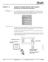
Optional DisplayTo minimize temperature alarms during start up, defrost, <strong>and</strong> temperature fluctuations, alarm delay timers can be configured. The controllers can beconfigured to start defrosting based on the elapsed system-on time, the accumulated run time of the compressor, or the difference in temperature betweenthe evaporator sensor <strong>and</strong> the control sensor. Defrosting can be terminated by elapsed time, the evaporator or control temperature sensor, or by atemperature switch. If the control temperature sensor fails, the compressor can be powered on, powered off, or follow a configured duty cycle.The controllers include the following physical features:• Knob for setpoint adjustment• Two temperature sensor inputs for a control probe <strong>and</strong> an evaporator probe• One digital input for an optional defrost termination switch• <strong>E71R</strong> Controller: One relay for a refrigeration compressor• <strong>E72R</strong> Controller: One relay for a refrigeration compressor <strong>and</strong> one relay for a defrost heater <strong>and</strong> fan• 90V to 240V AC switching power supply• Connection for configuration or optional display• Plastic enclosure <strong>and</strong> compact size for easy installation in most appliances• Customizable control parameters• Flash-memory microprocessor for quick <strong>and</strong> inexpensive configuration <strong>and</strong> firmware downloads at the factory or in the field• Adjustable mounting clips for panel or bracket mounting4 INSTALLATION4.1 Installing the controllerThe controller can be mounted in a panel cutout with the LEDs showing, mounted behind a panel with only the adjustment shaft exposed, or mountedcompletely within the case.To mount the controller with the face exposed, cut a 2 26/32” by 1 5/32” (71 mm x 29 mm) hole in the panel. Insert the controller from the outside of thepanel <strong>and</strong> slide a mounting clip onto each side of the controller from behind the panel.Optionally, the controller can be mounted to a bracket inside the case.2 26/32” (71 mm)DRAFT VERSIONExposed FaceCut-out1 5/32”(29 mm)Type E7 <strong>Eco</strong><strong>Cool</strong> Electronic <strong>Temperature</strong> <strong>and</strong> Defrost Controllers©2008 Invensys Controls All rights reserved.5
4.1.1 Wiring the controllerWARNING: Before wiring the controller, make sure that the refrigeration unit, fan, heater, <strong>and</strong> controller are not connected to the electrical supply.Do not apply voltage to the digital input.WARNING: If the compressor <strong>and</strong> a fan are connected to the same relay on the controller, the total current drawn by the compressor <strong>and</strong> fan mustnot exceed the value shown in section 8.4 Terminations.Use insulated spade connectors to connect the controller to the output loads. If your line voltage uses a neutral line <strong>and</strong> a phase line, connect the phase li<strong>net</strong>o the phase terminal(s) on the controller. Line 1 <strong>and</strong> Line 2 connections on the controller are not phase dependent. Connect the control sensor, optionalevaporator sensor, <strong>and</strong> optional defrost termination switch using the screw terminal block.<strong>E71R</strong>Wiring Example<strong>E71R</strong> with Control Sensor <strong>and</strong> Optional Evaporator SensorDRAFT VERSION<strong>E72R</strong>Wiring Example<strong>E72R</strong> With Control Sensor, Optional Evaporator Sensor, Defrost Heater, <strong>and</strong> Defrost FanType E7 <strong>Eco</strong><strong>Cool</strong> Electronic <strong>Temperature</strong> <strong>and</strong> Defrost Controllers©2008 Invensys Controls All rights reserved.6
4.2 Mounting the displayED1The optional display can be flush mounted in a panel cutout up to 30ft (10m) from the controller. To mount the display flush to the panel, cut a 2.32” by 1”(64mm x 31mm) hole in the panel. Insert the display from the outside of the panel. Friction tabs on the sides of the display hold it in place.DRAFT VERSIONDisplayMountingCut-out1”(25.4 mm)2.32” (58.9 mm)4.3 Wiring the displayUse the Interface Box, Copy Card, <strong>and</strong> Display TTL Connector on the controller to connect to the display.5 FUNCTIONS AND FEATURES5.1.1 User controlThe adjustment knob can be rotated to select any control temperature within the configured range.The OFF <strong>and</strong> ON positions of the adjustment knob can be set to specific angles relative to full counter clockwise. Rotating the adjustment knob fully counterclockwise (to OFF) powers off the controller <strong>and</strong> compressor immediately. However, hazardous voltage remains. The controller, compressor, defrost heater,<strong>and</strong> defrost fan must be disconnected, prior to service, using a separate switch. If the On/Off Function is enabled <strong>and</strong> the knob is in the OFF position, rotatingthe knob clockwise powers on the controller.5.1.2 Control modeThe controller cycles the compressor or refrigeration solenoid valve to maintain the selected control temperature.DifferentialsThe warm <strong>and</strong> cold adjustment knob positions are configured using four setpoints. Cut-In Warm <strong>and</strong> Cut-Out Warm are the setpoints for the warm position.Cut-In Cold <strong>and</strong> Cut-Out Cold are the setpoints for the cold position. The cold position is full clockwise rotation. The warm position is full counter clockwiserotation or, if the On/Off Function is enabled, the specified angle. When the user sets the adjustment knob to a setpoint between the warm <strong>and</strong> coldpositions, the Cut-In <strong>and</strong> Cut-Out setpoints are calculated by the controller. The setpoints can be configured using Celsius or Fahrenheit units.Cut-In Warm SetpointCut-Out Warm SetpointUser selectedCut-In <strong>and</strong> Cut-Out Setpoints<strong>Temperature</strong>Cut-InCut-OutKnob PositionCut-In Cold SetpointCut-Out Cold SetpointWarm PositionOFFUser SelectedPositionCold PositionType E7 <strong>Eco</strong><strong>Cool</strong> Electronic <strong>Temperature</strong> <strong>and</strong> Defrost Controllers©2008 Invensys Controls All rights reserved.7
When the adjustment knob is set to the warm position <strong>and</strong> the controlled space temperature is equal to or greater than the Cut-In warm setpoint, thecompressor or solenoid valve is energized until the controlled space temperature is equal to or less than the Cut-Out warm setpoint. Similarly, when theadjustment knob is set to cold, the compressor or solenoid valve is energized when the temperature is equal to or greater than the Cut-In cold setpoint <strong>and</strong>de-energized when the temperature is equal to or below the Cut-Out cold setpoint. For adjustment knob positions between warm <strong>and</strong> cold, the controllerinterpolates the cut-in <strong>and</strong> cut-out setpoints from the four configured setpoints.The optional display changes from the control temperature to the Cut-Out setpoint during adjustment <strong>and</strong> reverts to the control temperature three secondsafter adjustment. Because the four setpoints are configured independently, the differential can remain constant or change linearly between the cold <strong>and</strong>warm settings.Refer to the graphs below for various setting scenarios.WarmPositionSetpointsNarrow DifferentialWarmPositionSetpointsWide DifferentialCut-In<strong>Temperature</strong>Cut-In<strong>Temperature</strong>Cut-OutColdPositionSetpointsCut-OutColdPositionSetpointsAdjustment Knob Setpoint RangeAdjustment Knob Setpoint RangeWarmPositionSetpointsConstant Cut-InWarmPositionSetpointsVariable Differential<strong>Temperature</strong>Cut-InCut-OutColdPositionSetpoints<strong>Temperature</strong>Cut-InCut-OutColdPositionSetpointsDRAFT VERSIONAdjustment Knob Setpoint RangeAdjustment Knob Setpoint RangeWarmPositionSetpointsFixed Setpoint<strong>Temperature</strong>Cut-InCut-OutColdPositionSetpointsAdjustment Knob Setpoint RangeThe compressor can be protected against short cycling by three time delays. The Compressor Minimum Off Time at Start delay begins counting downwhen the controller is powered on. The compressor cannot be powered on before this delay expires. If the ON/OFF function is enabled, the timer does notcount down while the adjustment knob is in the OFF position. When the compressor is powered on the Compressor Minimum On Time delay beginscounting down. The compressor is not powered off by the controller before this delay expires regardless of the control temperature or setpoint. However, ifthe adjustment knob is rotated to OFF the controller <strong>and</strong> compressor are immediately powered off. When the controller powers off the compressor, theCompressor Minimum Off Time delay begins counting down. The compressor is not powered on before this timer expires regardless of control temperatureor setpoint.TIP:An excessive Compressor Minimum On Time or Compressor Minimum Off Time can force the temperature past an alarm threshold <strong>and</strong> trigger atemperature alarm.Type E7 <strong>Eco</strong><strong>Cool</strong> Electronic <strong>Temperature</strong> <strong>and</strong> Defrost Controllers©2008 Invensys Controls All rights reserved.8
DRAFT VERSIONTypicalCompressorCyclesCompressor or RefrigerationCut-InOFFONOFFONOFF<strong>Temperature</strong>Cut-OutTimeCompressorMinimumOn TimeControllerPower onCompressorMinimumOff Timeat StartupCompressorMinimumOn TimeCompressorMinimumOFF Time5.1.3 Status indicationsThree LEDs in the face of the controller indicate the status of the controller. The green LED illuminates while the compressor is powered on. The yellow LEDilluminates while the controller is in a defrost cycle. The red LED illuminates if the control temperature exceeds an alarm threshold or flashes if atemperature sensor circuit is shorted or open. The remote display includes three red LEDs that provide the same indications (see 5.1.6 Display).CompressorPowered OnDefrost Cycle<strong>Temperature</strong> orSensor Alarm5.1.4 Defrost controlThe defrost functionality can be based on the appliance operating time between defrosting cycles, the accumulated compressor run time between defrostingcycles, or it can be disabled. If the Defrost Function is disabled, all defrosting features are disabled.The controller can start a defrost cycle when it is powered on or after the expiration of the Time to First Defrost delay. If Defrost Cycle at Power On isenabled, the controller starts a defrost cycle when it is powered ON or after a power interruption (power cycle). If Defrost Cycle at Power On is disabled, theTime to First Defrost timer starts counting down when the controller is powered on. The controller starts a defrost cycle when the timer expires. After thecompletion of the first defrost cycle, the Time to subsequent defrosts timer starts counting down. When it expires, defrost starts. At the end of the defrostcycle, the timer resets <strong>and</strong> restarts.Type E7 <strong>Eco</strong><strong>Cool</strong> Electronic <strong>Temperature</strong> <strong>and</strong> Defrost Controllers©2008 Invensys Controls All rights reserved.9
Time InitiatedDefrostDefrost Termination TempDefrostTerminationCut-In<strong>Temperature</strong>Compressor or RefrigerationOFF ON OFF ON OFFON OFF ON OFFCut-OutTimeDRAFT VERSIONControllerPower onTime toFirst DefrostCompressorMinimum OnTimeTime toSubsequent DefrostsThe controller can also be configured with a <strong>Temperature</strong> Initiated Defrost Function to start defrosting if it senses too great a difference between thecontrol temperature <strong>and</strong> the evaporator temperature. <strong>Temperature</strong> Initiated Defrost Time Delay begins counting down if the evaporator temperature is lessthan 32ºF (0ºC) <strong>and</strong> an excessive temperature difference is sensed. Defrost starts if the temperature difference still exists when the delay expires. Thistemperature initiated defrost delay prevents defrost from starting if the air space temperature temporarily increases (e.g. the door is left open). Thetemperature difference <strong>and</strong> delay are both configured.<strong>Temperature</strong> Initiated Defrost Time Delay after Defrost begins counting down when refrigeration starts after defrost. This delay is typically longer than<strong>Temperature</strong> Initiated Defrost Time Delay to prevent another defrost before the sensed temperatures return to normal. When <strong>Temperature</strong> Initiated DefrostTime Delay after Defrost expires, the controller resumes use of <strong>Temperature</strong> Initiated Defrost Time Delay as described above. <strong>Temperature</strong> Initiated DefrostTime Delay after Defrost permits a shorter <strong>Temperature</strong> Initiated Defrost Time Delay without the risk of starting defrost due to a lagging control temperatureafter defrost.<strong>Temperature</strong> initiated defrost is independent of time initiated defrost <strong>and</strong> can start before the Time to subsequent defrosts timer expires.<strong>Temperature</strong>Initiated DefrostDefrost Termination TempDefrost TerminationControl Minus EvaporatorStarts Defrost DelayCut-InCut-Out<strong>Temperature</strong>ControlSensorEvaporatorSensorTimeDefrost DelayDefrost StartDefrost DelayAfter Defrost(Defrost Prohibited)Type E7 <strong>Eco</strong><strong>Cool</strong> Electronic <strong>Temperature</strong> <strong>and</strong> Defrost Controllers©2008 Invensys Controls All rights reserved.10
The <strong>E71R</strong> controller allows only off-cycle defrost by powering off the compressor. The <strong>E72R</strong> controller includes the following Defrost Method options:• Off Cycle: powers off the compressor• Electric: powers off the compressor <strong>and</strong> powers on a heating element• Reverse Cycle: powers on the compressor <strong>and</strong> powers on a valve that reverses the cooling cycle to pump heat into the evaporator coilDefrost heat <strong>and</strong> an optional evaporator fan are controlled by the second relay on the <strong>E72R</strong>.When defrosting begins, the Defrost Duration timer starts counting down real time. Defrosting ends when one of the following occurs, depending onyour configuration:• The Defrost Duration timer expires• The control temperature increases to the Defrost Termination <strong>Temperature</strong>• The evaporator temperature (evaporator sensor) rises to the Defrost Termination <strong>Temperature</strong>• The optional defrost termination switch is closedIf evaporator or control sensor termination is enabled, defrosting can terminate before the Defrost Duration timer expires. In this case the timer servesas a failsafe.When defrost is terminated, the optional Drip Time delay starts counting down. If the <strong>E72R</strong> is being used, the defrost relay switches position: The defrostheater is powered off or the reverse cycle solenoid returns to the cooling position, <strong>and</strong> the evaporator fan is powered on. The compressor is not powered onuntil the Drip Time delay expires. If the <strong>E71R</strong> is being used, the compressor remains powered off during the drip time. This delay is used primarily withelectrical or reverse cycle defrost to allow water removal between terminating heat <strong>and</strong> powering on the compressor. When the Drip Time delay expires, theTime to subsequent defrosts timer resets <strong>and</strong> begins counting down to the next defrost cycle.With both the Time to subsequent defrosts timer <strong>and</strong> the <strong>Temperature</strong> Initiated Defrost Function enabled the appliance is protected against excessive icebuildup, which may accumulate quickly in abnormally high humidity environments.5.1.5 AlarmsIf the controlled temperature exceeds an alarm threshold or a sensor circuit fails, the red alarm LEDs on the controller <strong>and</strong> optional display indicate the typeof fault that has occurred. Additionally, the optional display identifies a sensor failure. The table below shows faults <strong>and</strong> indications.DRAFT VERSIONAlarm LEDIndicationsFault Display Red Alarm LED<strong>Temperature</strong> Alarm Control sensor temperature IlluminatedControl Sensor Circuit Failure E1 FlashingEvaporator Sensor Circuit Failure Alternates between E2 <strong>and</strong> the control sensor temperature Flashing5.1.5.1 <strong>Temperature</strong>If temperature alarms are enabled, four setpoints define the high <strong>and</strong> low temperature alarms for the cold <strong>and</strong> warm positions. Similar to the temperaturesetpoint, the high temperature alarm threshold is interpolated across the adjustment range from the configured high temperature alarm cold <strong>and</strong> hightemperature alarm warm setpoints. The low temperature alarm threshold is interpolated from the low temperature alarm setpoints at the cold <strong>and</strong> warmpositions. The <strong>Temperature</strong> Alarm Differential prevents alarm cancellation until the control temperature returns past the alarm threshold by the amount ofthe differential. A high temperature alarm remains on until the temperature decreases to less than the high temperature alarm minus the differential. A lowtemperature alarm remains on until the temperature increases to more than the low temperature alarm plus the differential.SetpointsHigh <strong>Temperature</strong> AlarmWarm Setpoint<strong>Temperature</strong> AlarmCut-In WarmAlarm CancellationCut-InHigh <strong>Temperature</strong> AlarmCold Setpoint<strong>Temperature</strong> Alarm DifferentialCut-Out WarmLow <strong>Temperature</strong> AlarmWarm Setpoint<strong>Temperature</strong>Cut-OutAlarm Cancellation<strong>Temperature</strong> AlarmAdjustment Knob PositionCut-In ColdCut-Out Cold<strong>Temperature</strong> Alarm DifferentialLow <strong>Temperature</strong> AlarmCold SetpointWarm PositionOFFCold PositionType E7 <strong>Eco</strong><strong>Cool</strong> Electronic <strong>Temperature</strong> <strong>and</strong> Defrost Controllers©2008 Invensys Controls All rights reserved.11
If the control temperature crosses an alarm threshold, the <strong>Temperature</strong> Alarm Time Delay begins counting down. If the timer expires <strong>and</strong> the temperaturehas not returned past the alarm differential, the red alarm LED on the controller (<strong>and</strong> optional display) illuminates. If the control temperature returns past thethreshold by the amount of the differential before the alarm delay expires, the pending alarm is cancelled, <strong>and</strong> the timer is reset. When the temperaturereturns past the threshold by the amount of the differential the alarm is cancelled <strong>and</strong> the <strong>Temperature</strong> Alarm Time Delay is reset. The <strong>Temperature</strong> AlarmTime Delay reduces the possibility of temperature fluctuations causing false alarms.A <strong>Temperature</strong> Alarm Disable Time after Start up timer prevents alarms while the appliance decreases the temperature after being powered on. A<strong>Temperature</strong> Alarm Delay After Defrost prevents false alarms while the appliance decreases the temperature after defrost. This allows for a shorter<strong>Temperature</strong> Alarm Time Delay <strong>and</strong> a longer delay time after defrost only.DRAFT VERSION<strong>Temperature</strong>AlarmsHigh <strong>Temperature</strong> Alarm<strong>Temperature</strong> Alarm Differential<strong>Temperature</strong> AlarmTime Delay starts<strong>Temperature</strong> AlarmActivatedAlarm CancelledCut-In<strong>Temperature</strong>Cut-Out<strong>Temperature</strong> Alarm DifferentialLow <strong>Temperature</strong> AlarmTime<strong>Temperature</strong> AlarmTime DelaySensor Failure5.1.5.2 FaultsIf a sensor circuit is shorted or open, the Sensor Fault Monitoring Time timer starts counting down. If the timer expires before the fault is corrected the redalarm LED flashes. Refer to 5.1.7 Sensor failure mode. When the fault is fixed, the timer resets <strong>and</strong> the red alarm LED is extinguished (if a temperature alarmis in effect the LED is illuminated). If a sensor failure alarm <strong>and</strong> a temperature alarm occur at the same time, the red alarm LED flashes to indicate thesensor failure.ED1During a control sensor failure, the optional display shows E1.ED1During an evaporator sensor failure, the optional display shows E2 for one second, the temperature of the control sensor for three seconds, <strong>and</strong> repeats.If both sensors fail, the display shows E1.NOTE:When the controller is powered on, an LED flashing sequence indicates that the controller firmware is operating properly. Each LED flashes forone second in sequence <strong>and</strong> then all three illuminate for two seconds. If the red alarm LED remains illuminated after the controller is poweredon, a check sum error has occurred <strong>and</strong> the controller’s firmware must be updated using a computer <strong>and</strong> the interface box or a copy card (referto 6.2.8) No additional external alarm indication is available.Type E7 <strong>Eco</strong><strong>Cool</strong> Electronic <strong>Temperature</strong> <strong>and</strong> Defrost Controllers©2008 Invensys Controls All rights reserved.12
5.1.6 DisplayThe optional display has two digits, a negative sign, <strong>and</strong> three status LEDs. It displays the range -99 to 99 <strong>and</strong> the characters dF. Normally the display showsthe control sensor temperature. The display shows the selected cut-out setpoint during adjustment <strong>and</strong> for three seconds after the adjustment is made.Sensor faults, temperature alarms, compressor or solenoid valve operation, <strong>and</strong> defrost are indicated by the display LEDs as they are by the controller LEDs.CompressorPowered OnDefrost Cycle<strong>Temperature</strong> orSensor AlarmED1DRAFT VERSIONSensor FailureProtection5.1.7 Sensor failure modeIf a sensor circuit becomes shorted or open, the Sensor Fault Monitoring Time timer begins counting down. If the timer expires before the fault iscorrected, the controller issues an alarm (refer to 5.1.5 for display indication) <strong>and</strong> uses the configured Sensor Failure Mode to power off, power on, or dutycycle the compressor. The compressor on time <strong>and</strong> compressor off time of the duty cycle can be configured. When fault is fixed, the timer resets <strong>and</strong> thealarm is cancelled.CompressorOff Time Ifsensor FailedCompressorOn Time Ifsensor FailedOnCompressor orRefrigerationStatusOff On Off OnDuty CycleOffTimeType E7 <strong>Eco</strong><strong>Cool</strong> Electronic <strong>Temperature</strong> <strong>and</strong> Defrost Controllers©2008 Invensys Controls All rights reserved.13
DRAFT VERSION6 DEVICE AND SOFTWARE CONFIGURATION6.1 Controller <strong>and</strong> interface box6.1.1 Interface box overviewThe interface box allows communication between the controller <strong>and</strong> a computer for configuration download <strong>and</strong> upload <strong>and</strong> for firmware installation.Copy Card JackInterface BoxCable ConnectionPower JackRS-232 DB-9Connector6.1.2 Connect the interface box to the computer <strong>and</strong> <strong>E71R</strong> or <strong>E72R</strong> controllerConnect the power adapter to the interface box <strong>and</strong> plug in the adapter.Connect the interface box to the computer using either the RS232 db9 serial cable OR the USB to RS232 db9 converter cable (shown in blue below).Ensure that the controller is not connected to power; power is supplied by the interface box.Connect the controller to the interface box.WARNING: The controller must not be connected to power while configuring it with the interface box.Type E7 <strong>Eco</strong><strong>Cool</strong> Electronic <strong>Temperature</strong> <strong>and</strong> Defrost Controllers©2008 Invensys Controls All rights reserved.14
DRAFT VERSION6.2 <strong>Eco</strong><strong>Cool</strong> configuration software6.2.1 Minimum computer requirementsTo use the <strong>Eco</strong><strong>Cool</strong> configuration software your computer must meet or exceed the following minimum requirements:• Processor: Intel ® Pentium ® 4 500 MHz• Operating System: Microsoft® Windows® XP or Microsoft Vista®• RAM: 64 MB• Physical port: Available db9 RS232 or USB 1.06.2.2 Software overviewUse the <strong>Eco</strong><strong>Cool</strong> configuration software to configure <strong>and</strong> save controller configurations, download a configuration file to a controller, upload a configurationfile from a controller, create configuration reports, or update the controller firmware. To simplify configuration, there are eight parameters tabs.6.2.3 Install <strong>and</strong> start <strong>Eco</strong><strong>Cool</strong> configuration softwareInsert the <strong>Eco</strong><strong>Cool</strong> configuration software CD into your computer.Open the <strong>Eco</strong><strong>Cool</strong> configuration software folder on the CD, click the setup.exe icon, <strong>and</strong> follow the installation prompts.To start <strong>Eco</strong><strong>Cool</strong> configuration software click Start, select <strong>Eco</strong><strong>Cool</strong> configuration software, <strong>and</strong> click <strong>E72R</strong>.NOTE:The <strong>Eco</strong><strong>Cool</strong> configuration software can be used without connecting the interface box to your computer.6.2.4 Uninstalling <strong>Eco</strong><strong>Cool</strong> configuration softwareTo remove <strong>Eco</strong><strong>Cool</strong> configuration software from your computer, open the Add or Remove Programs control panel <strong>and</strong> select <strong>Eco</strong><strong>Cool</strong> configuration software.After uninstalling <strong>Eco</strong><strong>Cool</strong> configuration software the <strong>Eco</strong><strong>Cool</strong> configuration software folder, containing configuration <strong>and</strong> reports subdirectories, remains inthe Program Files directory. To completely uninstall <strong>Eco</strong><strong>Cool</strong> configuration software, manually delete the <strong>Eco</strong><strong>Cool</strong> configuration software folder from theProgram Files directory. All configuration files <strong>and</strong> reports are erased when the <strong>Eco</strong><strong>Cool</strong> configuration software folder is deleted.TIP:All configuration files <strong>and</strong> reports are erased if the <strong>Eco</strong><strong>Cool</strong> configuration software folder is deleted.6.2.5 Tabbed configuration parametersSelect from the eight tabs on the left side of the program to create or edit programs for the controllers.• Configuration: temperature units, defrost method, sensor use, adjustment knob on <strong>and</strong> off positions• Setpoints: compressor cut-in (power on) <strong>and</strong> cut-out (power off) temperatures for adjustment knob warm <strong>and</strong> cold positions• Compressor: short cycle prevention timers• Display: display behavior during defrost cycles <strong>and</strong> temperature offset• Fan: fan operation during compressor off cycle (for higher temperature application without defrost)• Alarm: temperature <strong>and</strong> timer settings for excessively high or low temperatures• Fault: controller response to sensor failure• Defrost: defrost timer, temperature, <strong>and</strong> failsafe parametersSettings made on one tab can affect parameters on other tabs. If a change causes a parameter on another tab to be disabled a popup window indicatesthe change.Changed parameter popup window:Type E7 <strong>Eco</strong><strong>Cool</strong> Electronic <strong>Temperature</strong> <strong>and</strong> Defrost Controllers©2008 Invensys Controls All rights reserved.15
DRAFT VERSION6.2.5.1 ConfigurationUse the configuration tab to specify the general operation of the controller <strong>and</strong> the controller’s use of parameters that are programmed on other tabs.Controller Operation temperature UnitsSelect Fahrenheit or Celsius as the unit of temperature measurement <strong>and</strong> control. Changing this parameter changes the temperature unit throughout thecontroller program <strong>and</strong> recalculates temperature values shown in the tabs <strong>and</strong> on the display.Defrost MethodSelect the method of defrosting to be used. Defrosting is started according to the parameters on the Defrost tab.• Electric can be used by the <strong>E72R</strong> controller to control the defrost relay during a defrost cycle. The <strong>E71R</strong> does not have a defrost relay, but powers offthe compressor during an electric defrost.• Off Cycle can be used by the <strong>E71R</strong> <strong>and</strong> <strong>E72R</strong> controllers to cause the compressor to remain powered off for the duration of the defrost cycle.• Reverse Cycle can be used by the <strong>E72R</strong> controller to actuate a solenoid valve that reverses the cooling cycle to act as a heat pump to defrostaccumulated ice. The compressor remains powered on during defrost.Evaporator <strong>Temperature</strong> SensorSelect Enabled if the controller is using an evaporator temperature sensor (see 5.1.4 Defrost Control). Select Disabled if the controller is not using anevaporator temperature sensor.NOTE: If Enabled is selected <strong>and</strong> an evaporator temperature sensor is not connected to the controller, the controller indicates a sensor failure.Defrost Termination Method• Select Disable to force defrost to terminate only due to elapsed time (Defrost Duration on the Defrost tab).• Select Evaporator Sensor to use the sensed evaporator temperature to end defrosting (Defrost Termination on the Defrost tab).• Select Control Sensor to use the control temperature to end defrosting (Defrost Termination on the Defrost tab).• Select Switch (NO) to use a separate normally open defrost termination switch. Defrost is terminated when the switch is closed. If Switch is selected,the controller will still end a defrost cycle based on the elapsed time even if the switch is not closed.If either sensor is selected, enter the Defrost Termination <strong>Temperature</strong> for the sensor on the Defrost tab. The selection of Defrost Termination Methoddoes not affect how defrosting starts or the <strong>Temperature</strong> Initiated Defrost Function on the Defrost tab.Type E7 <strong>Eco</strong><strong>Cool</strong> Electronic <strong>Temperature</strong> <strong>and</strong> Defrost Controllers©2008 Invensys Controls All rights reserved.16
DRAFT VERSIONOn/Off FunctionSelect Enable to allow the adjustment knob to power off the compressor <strong>and</strong> controller <strong>and</strong> to adjust the setpoint. Select Disabled to allow only setpointadjustment by the adjustment knob.Potentiometer (Adjustment Knob)These settings are unavailable if On/Off Function is disabled. Enter the Potentiometer Off Position to set the angle of the adjustment knob, relative to fullcounter clockwise, that powers off the controller <strong>and</strong> compressor. Enter the Potentiometer On Position to set the angle of the adjustment knob, relative to fullcounter clockwise, that powers on the controller.6.2.5.2 SetpointsUse the Setpoints tab to specify the controller setpoints - refrigeration Cut-In <strong>and</strong> Cut-Out values during normal operation.NOTE: To define a fixed non-adjustable setpoint, configure the Cut-In Warm setpoint equal to the Cut-In Cold setpoint. Configure the Cut-Out Warm setpointequal to the Cut-Out Cold setpoint. Refer to the Fixed Setpoint graph in section 5.1.2.Cut-In WarmSpecify the setpoint that causes the compressor to power on when the adjustment knob is set to the warm position (counter clockwise).Cut-Out WarmSpecify the setpoint that causes the compressor to power off when the adjustment knob is set to the warm position (counter clockwise).Cut-In ColdSpecify the setpoint that causes the compressor to power on when the adjustment knob is set to the cold position (clockwise).Cut-Out ColdSpecify the setpoint that causes the compressor to power off when the adjustment knob is set to the cold position (clockwise).Cut-in <strong>and</strong> cut-out setpoints for positions between warm <strong>and</strong> cold are calculated as linear interpolations from the configured cold <strong>and</strong> warm setpoints.NOTE: If the On/Off Function is enabled on the Configuration tab, the Potentiometer On Position specifies the adjustment knob angle that selects the warmsetpoint.Type E7 <strong>Eco</strong><strong>Cool</strong> Electronic <strong>Temperature</strong> <strong>and</strong> Defrost Controllers©2008 Invensys Controls All rights reserved.17
DRAFT VERSION6.2.5.3 DefrostUse the Defrost tab to specify the conditions that cause defrosting to start <strong>and</strong> end.Defrost FunctionDefine the defrost schedule timing interval or disable the defrost function. Selecting System Run Time specifies that the time interval between defrost (Timeto subsequent defrosts) is defined by the time that the controller is powered on <strong>and</strong> restarts if the controller is power cycled. Selecting Compressor RunTime specifies that the defrost timing interval is defined as the accumulated time that the compressor is powered on <strong>and</strong> restarts if the controller is powercycled. The defrost function can also be disabled.NOTE: If you use <strong>Temperature</strong> Initiated Defrost, you must still select System Run Time or Compressor Run Time as a failsafe maximum time betweendefrosting cycles.Defrost Cycle at Power OnSelect Enable to start a defrost cycle each time the controller is switched on or the appliance is power cycled in addition to the scheduled <strong>and</strong> temperatureinitiated defrost cycles. Select Disable to only allow scheduled <strong>and</strong> temperature initiated defrosting.Defrost Termination <strong>Temperature</strong>Specifies the temperature that causes defrosting to end (<strong>and</strong> drip time to start – if drip time is defined). This is either the Control Sensor temperature or theEvaporator Sensor temperature as chosen on the Configuration tab. This parameter is unavailable if the Defrost Function is disabled. If the defrosttermination method is based on the digital input Switch (NO) (set on the Configuration tab) this setting is disregarded by the controller.WARNING: The controller terminates defrost when the digital input dry contacts close – Do not apply voltage.Time to First DefrostSpecifies how long the controller waits before starting a defrosting cycle each time it is powered on. The timer that is used, System Run Time or CompressorRun Time, is specified in Defrost Function. This parameter is unavailable if Defrost Cycle at Power On is enabled.Time to Subsequent DefrostsSpecify how long the controller waits to start the second <strong>and</strong> subsequent defrost cycles after being powered on. The timer starts when the Drip Time timerexpires or, if drip time is not being used, when the defrost terminates either on failsafe time (Defrost Duration) or temperature (Defrost Termination<strong>Temperature</strong>). A temperature initiated defrost cycle can occur before the Time to Subsequent Defrosts timer expires.Type E7 <strong>Eco</strong><strong>Cool</strong> Electronic <strong>Temperature</strong> <strong>and</strong> Defrost Controllers©2008 Invensys Controls All rights reserved.18
DRAFT VERSIONDefrost DurationSpecifies the maximum duration of a defrost cycle (also called failsafe). When the Defrost Duration time expires the defrost cycle ends <strong>and</strong>, if Drip Time isconfigured, the Drip Time starts. If Drip Time is not configured, the controller immediately powers on the compressor <strong>and</strong> resumes refrigeration.Drip TimeSpecifies how long the controller waits to resume refrigeration after defrost. During drip time, the compressor <strong>and</strong> defrost relay (<strong>E72R</strong> only) are de-energizedto allow water to drip off of the coil.NOTE: If the evaporator fan is wired to the NC contact on the defrost relay (<strong>E72R</strong> only), the fan will power on at the end of defrost. To delay the fan actionuntil drip time is expired use an external fan delay thermostat.<strong>Temperature</strong> Initiated Defrost FunctionSelect Enable to allow defrost based on a comparison of the air space temperature <strong>and</strong> the evaporator temperature. Specify the difference in sensedtemperature (control sensor minus evaporator sensor) that initiates defrosting. Enter the <strong>Temperature</strong> Initiated Defrost Time Delay to specify how long themeasured temperature difference must exist before defrost starts. Enter the <strong>Temperature</strong> Initiated Defrost Time delay after Defrost to specify how longthe controller waits after the termination of a defrost cycle or drip time (depending on configuration) before it allows a temperature initiated defrost. Thisdelay allows the sensed temperatures to return to normal before a temperature initiated defrost cycle can occur.NOTE: Evaporator <strong>Temperature</strong> Sensor on the Configuration tab must be enabled to configure <strong>and</strong> use the <strong>Temperature</strong> Initiated Defrost Function.6.2.5.4 AlarmUse the Alarm tab to specify temperature conditions that illuminate the alarm LED on the controller <strong>and</strong> on the display.<strong>Temperature</strong> Alarm EnableSelect Enable to enable temperature alarms or select Disable to disable the setting <strong>and</strong> display of temperature alarms.NOTE: <strong>Temperature</strong> Alarm Enable does not affect alarms due to a control or evaporator sensor short or open circuit, or a firmware (check sum) error.High <strong>Temperature</strong> Alarm – Warm PositionSpecifies the sensed high temperature setpoint that causes an alarm when the adjustment knob is in the warm position. Control sensor temperatures equalto or greater than this threshold cause an alarm when the adjustment knob is in the warm position.Type E7 <strong>Eco</strong><strong>Cool</strong> Electronic <strong>Temperature</strong> <strong>and</strong> Defrost Controllers©2008 Invensys Controls All rights reserved.19
DRAFT VERSIONLow <strong>Temperature</strong> Alarm – Warm PositionSpecifies the sensed low temperature setpoint that causes an alarm when the adjustment knob is in the warm position. Control sensor temperatures equalto or less than this threshold cause an alarm when the adjustment knob is in the warm position.High <strong>Temperature</strong> Alarm – Cold PositionSpecifies the sensed high temperature setpoint that causes an alarm when the adjustment knob is in the cold position. Control sensor temperatures equal toor greater than this threshold cause an alarm when the adjustment knob is in the cold position.Low <strong>Temperature</strong> Alarm – Cold PositionSpecifies the sensed low temperature setpoint that causes an alarm when the adjustment knob is in the cold position. Control sensor temperatures equal toor less than this threshold cause an alarm when the adjustment knob is in the cold position.If the user selects a control setpoint between the warm <strong>and</strong> cold positions, the alarm thresholds are calculated by the controller as linear interpolations fromthe temperaturealarm setpoints.<strong>Temperature</strong> Alarm DifferentialSpecifies the amount of temperature correction required to cancel a temperature alarm. A high temperature alarm is cancelled when the temperature is lessthan the alarm threshold minus the differential. A low temperature alarm is cancelled when the temperature is greater than the low temperature alarmthreshold plus the differential.<strong>Temperature</strong> Alarm Time DelaySpecifies the minimum time that a sensed control temperature must be beyond a temperature alarm threshold before a temperature alarm occurs.<strong>Temperature</strong> Alarm Disable Time after Start upSpecifies how long temperature alarms are disabled after the controller is powered on.<strong>Temperature</strong> Alarm Delay After DefrostSpecifies the maximum time delay before an alarm is activated when the control temperature is beyond an alarm threshold after defrost is terminated bytime or temperature or after drip time has ended - if used.6.2.5.5 CompressorUse the Compressor tab to set compressor protection delays for the minimum power on <strong>and</strong> power off periods for the compressor. These minimum timeperiods can be used to protect the compressor against short cycling.NOTE: Although the Compressor Minimum Off Time can be set as short as zero seconds, time should be provided to protect the compressor against short-cycling.Type E7 <strong>Eco</strong><strong>Cool</strong> Electronic <strong>Temperature</strong> <strong>and</strong> Defrost Controllers©2008 Invensys Controls All rights reserved.20
DRAFT VERSIONCompressor Minimum Off Time at Start UpSpecifies how long the compressor remains powered off when the controller is powered on.Compressor Minimum On TimeSpecifies the minimum time that the compressor is powered on regardless of whether the control temperature decreases to less than the Cut-Out setpoint.Specify how long the compressor remains powered on before normal controller programming powers it off.NOTE: The adjustment knob off position immediately powers off the compressor.Compressor Minimum Off TimeSpecifies how long the compressor remains powered off before the controller powers it on. This timer must expire <strong>and</strong> the temperature must be greater thanthe Cut-In setpoint for the controller to power on the compressor.6.2.5.6 FaultUse the Fault tab to specify a controller’s response to an open or shorted control sensor.Sensor Failure ModeSelect Comp. Relays fails OPEN to power off the compressor if the control sensor circuit becomes open or shorted.Select Comp. Relays fails CLOSE to power on the compressor if the control sensor circuit becomes open or shorted.Select Duty Cycle to power cycle the compressor using the specified duty cycle regardless of the temperature.Compressor On Time If sensor FailedSpecify the compressor power ON portion of the duty cycle.Compressor Off Time If sensor FailedSpecify the compressor power OFF portion of the duty cycle.Sensor Fault Monitoring TimeSpecify how long a sensor failure (open or short circuit) must exist before the controller enters failure or fault mode.Type E7 <strong>Eco</strong><strong>Cool</strong> Electronic <strong>Temperature</strong> <strong>and</strong> Defrost Controllers©2008 Invensys Controls All rights reserved.21
DRAFT VERSION6.2.5.7 DisplayUse the Display tab to specify what is displayed during defrost <strong>and</strong> to specify a display temperature offset.Defrost Display LockSelect Show current “TEMP” to display the sensed control temperature during defrost.Select LOCK Display at Temp. Reading prior to Defrost to display, for the entire defrost cycle, drip time, <strong>and</strong> until the first compressor cut-out after defrost,the temperature that was sensed at the moment the defrost cycle started.Select Show “DF” during Defrost to display, for the entire defrost cycle, drip time, <strong>and</strong> until the first compressor cut-out after defrost, DF.NOTE: Show “DF” during Defrost causes the display to show DF after defrost has terminated.Display Unlock Time (hh:mm)This countdown timer cancels the display lock <strong>and</strong> resumes display of the current control temperature when it expires. The timer starts counting down whendefrost terminates (whether due to elapsed time or sensed temperature) or at the end of the drip time depending upon the configuration.Display <strong>Temperature</strong> OffsetThe sum of the Display <strong>Temperature</strong> Offset <strong>and</strong> the control sensor temperature is displayed.NOTE: Display <strong>Temperature</strong> Offset affects the display only <strong>and</strong> does not change setpoints or configuration parameters.Type E7 <strong>Eco</strong><strong>Cool</strong> Electronic <strong>Temperature</strong> <strong>and</strong> Defrost Controllers©2008 Invensys Controls All rights reserved.22
DRAFT VERSION6.2.5.8 FanUse the Fan tab to configure fan operation when Defrost Function is disabled.Defrost Function may be disabled in medium <strong>and</strong> warm temperature applications where defrost occurs naturally during the compressor off cycle (see 6.2.5.3Defrost). With Defrost Function disabled, Evaporator Fan Operation during Compressor off-cycle allows the fan to be powered on or powered off duringthe entire compressor off cycle.Disabling both Defrost Function <strong>and</strong> Evaporator Fan Operation during Compressor off-cycle prevents, the evaporator fan from running during the compressoroff cycle. In this case, Fan Delay Method can delay powering on the evaporator fan when refrigeration cycles on. The delay can be based on a time,evaporator temperature, or both. If Fan Delay Method is based on time, Fan Start Time Delay starts counting down when refrigeration resumes afterdefrost <strong>and</strong> powers on the evaporator fan when it expires.If Fan Delay Method is based on evaporator temperature, Fan Start Evaporator <strong>Temperature</strong> powers on the evaporator fan when the evaporatortemperature decreases to the Fan Start Evaporator <strong>Temperature</strong> setpoint.If Fan Delay Method is based on Both time <strong>and</strong> temperature, the Fan Start Time Delay timer must expire <strong>and</strong> the evaporator temperature must decrease tothe Fan Start Evaporator <strong>Temperature</strong> setpoint before the evaporator fan powers on.If Evaporator Fan Operation during Compressor off-cycle is disabled, Fan Shut down Time Delay can delay the evaporator fan power-off when thecompressor cycles off.6.2.6 Saving <strong>and</strong> opening configuration filesBy default, configuration files are saved to the C:\Program Files\<strong>Eco</strong>Soft Program\Configuration Files directory,but you can specify any directory. To save a configuration file, enter a file name in the File Name: field <strong>and</strong> clickSave Configuration File. Configuration files are named in <strong>Eco</strong><strong>Cool</strong> so that multiple configurations can be storedon your computer. However, the configuration file name is not included with the configuration file when it isdownloaded to a controller or copy card. Therefore, configuration files must be named when they are uploaded.All file names automatically get the .prm file name extension.To open a configuration file, select the configuration file <strong>and</strong> click Open Configuration File.Type E7 <strong>Eco</strong><strong>Cool</strong> Electronic <strong>Temperature</strong> <strong>and</strong> Defrost Controllers©2008 Invensys Controls All rights reserved.23
6.2.7 Transferring configuration filesYou can use the interface box <strong>and</strong> your computer to transfer configuration files between <strong>Eco</strong><strong>Cool</strong> configuration software <strong>and</strong> a controller. Configuration filescan be downloaded to the controller or copy card <strong>and</strong> uploaded to your computer.Disconnect power to the controller. Power is supplied by the interface box.Connect the controller to the interface box as shown below.Connect the interface box to the computer using either the RS232 db9 serial cable OR the USB to RS232 db9 converter cable (shown in blue below).WARNING: The controller must not be connected to power while configuring it with the interface box.DRAFT VERSIONTransferringFiles6.2.7.1 Downloading a configuration file to a controller from <strong>Eco</strong><strong>Cool</strong> configurationsoftware:Start <strong>Eco</strong><strong>Cool</strong> configuration software.Create a configuration or select the configuration file <strong>and</strong> click Open Configuration File to load the values into <strong>Eco</strong><strong>Cool</strong> configuration software.Click Download Config. to Controller.Follow the on screen prompts.Disconnect the controller from the interface box.6.2.7.2 Uploading a configuration file from a controller to <strong>Eco</strong><strong>Cool</strong> configuration software:Start <strong>Eco</strong><strong>Cool</strong> configuration software.Click Upload Config. from Controller.Follow the on screen prompts.Disconnect the controller from the interface box.The configuration is loaded into <strong>Eco</strong><strong>Cool</strong> configuration software <strong>and</strong> can be viewed or modified.To save the configuration file, enter a filename <strong>and</strong> click Save Configuration File.NOTE: Be sure that the correct File Name is displayed before you click Save Configuration File.Disconnect the controller from the interface box.Type E7 <strong>Eco</strong><strong>Cool</strong> Electronic <strong>Temperature</strong> <strong>and</strong> Defrost Controllers©2008 Invensys Controls All rights reserved.24
DRAFT VERSION6.2.8 Transferring firmware between <strong>Eco</strong><strong>Cool</strong> configuration software <strong>and</strong> a controllerYou can use the interface box <strong>and</strong> your computer to transfer firmware between <strong>Eco</strong><strong>Cool</strong> configuration software <strong>and</strong> a controller or copy card. Controllerfirmware can be updated in a controller using a copy card or <strong>Eco</strong><strong>Cool</strong> configuration software. Firmware can be reinstalled in a controller, if it becomescorrupted, using <strong>Eco</strong><strong>Cool</strong> configuration software. Firmware must be re installed on a controller if, when it is powered on, the LED startup sequence reports acheck sum error (refer to 5.1.5.2).NOTE: When firmware is installed on the controller, the existing configuration is erased.6.2.8.1 Installing firmware on a controller using <strong>Eco</strong><strong>Cool</strong> configuration software:Disconnect power to the controller.Connect the controller to the interface box as shown in section 6.2.7.Start <strong>Eco</strong><strong>Cool</strong> configuration software.Upload the configuration to <strong>Eco</strong><strong>Cool</strong> configuration software to create a backup file.Click Update Controller Firmware.Follow the on screen promptsDisconnect the controller from the interface box.6.2.8.2 Uploading firmware from a controller:Disconnect power to the controller.Connect the controller to the interface box as shown in 6.2.7.Start <strong>Eco</strong><strong>Cool</strong> configuration software.Click Update Controller Firmware <strong>and</strong> follow the on screen promptsDisconnect the controller from the interface box.6.2.9 Generating reportsYou can create a configuration parameters text file or spreadsheet file for Microsoft ® Excel ® .Create, open, or upload a configuration file.Select Excel or Text <strong>and</strong> click Generate.By default, the file is saved in the C:\Program Files\<strong>Eco</strong>Soft Program xxx\Report Files directory.Type E7 <strong>Eco</strong><strong>Cool</strong> Electronic <strong>Temperature</strong> <strong>and</strong> Defrost Controllers©2008 Invensys Controls All rights reserved.25
DRAFT VERSION6.2.10 Restoring default valuesClick Default Value to load default values into all parameters on all tabs in the <strong>Eco</strong><strong>Cool</strong> configuration software. Popup windows indicate which parametersare being changed.You can download the default values to a controller by following the steps in section 6.2.6.6.3 Copy cardYou can use a copy card to transfer firmware <strong>and</strong> configuration files into a controller or <strong>Eco</strong><strong>Cool</strong> configuration software. A firmware or configuration transferinto a controller using a copy card is fast, automatic, <strong>and</strong> does not require removal of the controller from the case. Configuration files <strong>and</strong> firmware cannotbe uploaded from a controller into a copy card. During a data transfer, both LEDs flash. When the data transfer completes successfully, the green LEDremains illuminated <strong>and</strong> the red LED is extinguished. If the red LED remains illuminated <strong>and</strong> the green LED is extinguished, the transfer failed.Red LED indicates a failed data transferGreen LED indicates a successful data transferConnector6.3.1 Transferring firmware between a copy card <strong>and</strong> <strong>Eco</strong><strong>Cool</strong> configuration softwareA bidirectional transfer between the copy card <strong>and</strong> the interface box places the newer firmware in both devices. If the newer firmware is in the copy card, itis copied into <strong>Eco</strong><strong>Cool</strong> configuration software. If the newer firmware is in <strong>Eco</strong><strong>Cool</strong> configuration software, it is copied into the copy card.Connect the power adapter to the interface box <strong>and</strong> plug in the adapter.Connect the interface box to the computer using the included RS232 db9 serial cable OR USB to RS232 db9 converter cable.Connect the copy card to the interface box. The copy card fits only one of the interface box connectors.Click Update Controller Firmware.During the file transfer, both LEDs on the copy card are illuminated.When the data transfer is completed, the green LED remains illuminated <strong>and</strong> the red LED is extinguished.If the red LED remains illuminated <strong>and</strong> the green LED is extinguished, the transfer failed.Disconnect the copy card from the interfaced box.Type E7 <strong>Eco</strong><strong>Cool</strong> Electronic <strong>Temperature</strong> <strong>and</strong> Defrost Controllers©2008 Invensys Controls All rights reserved.26
DRAFT VERSION6.3.2 Downloading a configuration from <strong>Eco</strong><strong>Cool</strong> configuration software into a copy cardOpen a configuration file in the <strong>Eco</strong><strong>Cool</strong> configuration software.Connect the copy card to the Interface Box.Click Download Config to Controller.Click OK <strong>and</strong> follow the on screen prompts.During the file transfer, both LEDs on the copy card are illuminated.When the data transfer is completed, the green LED remains illuminated <strong>and</strong> the red LED is extinguished.If the red LED remains illuminated <strong>and</strong> the green LED is extinguished, the transfer failed.NOTE: Firmware is not transferred during a configuration download from <strong>Eco</strong><strong>Cool</strong> configuration software.6.3.3 Uploading a configuration from a copy card into <strong>Eco</strong><strong>Cool</strong> configuration softwareConnect the copy card to the Interface Box.Click Upload Config from Controller.Enter a name for the configuration file.Click Save Configuration File.Disconnect the copy card from the Interface Box.NOTE: Firmware is not transferred during a configuration upload to <strong>Eco</strong><strong>Cool</strong> configuration software.6.3.4 Installing firmware or a configuration file into a controller from a copy cardNOTE: If the copy card contains both a later version of firmware than the controller <strong>and</strong> a configuration file, both will be installed onto the controller. If only anewer version of firmware is on the copy card, the configuration will be erased from the controller when the firmware is installed. If you are updatingfirmware only, back up the controller configuration to the copy card that contains the firmware.Disconnect power to the controller.Disconnect power to any device, such as a compressor or fan, that is connected to the controller. These devices do not need to be disconnected from thecontroller.Connect the copy card to the controller.Connect power to the controller to start the installation.During the file transfer, both LEDs on the copy card are illuminated.When the data transfer is completed, the green LED remains illuminated <strong>and</strong> the red LED is extinguished.If the red LED remains illuminated <strong>and</strong> the green LED is extinguished, the transfer failed.Disconnect copy card from the controller.Disconnect power to the controller.The controller is ready for use.Connect power to the controller.Connect power to any device, such as a compressor or fan, that is connected to the controller.Type E7 <strong>Eco</strong><strong>Cool</strong> Electronic <strong>Temperature</strong> <strong>and</strong> Defrost Controllers©2008 Invensys Controls All rights reserved.27
Parameter listThe Parameter List Table includes the default value, range, <strong>and</strong> resolution of all parameters that can be set using the <strong>Eco</strong>Soft Program.DRAFT VERSIONCase name, location or ID: ____________________________________________________________________Configuration name (e.g. Ice Cream.prm): __________________________________________________________Tab Ref Parameter Description Default Min Max ResolutionConfigurationValue1Controller Operation<strong>Temperature</strong> UnitsFahrenheit°C (Celsius) or °F (Fahrenheit)2 Defrost Method Electric Electric, Off Cycle, or Reverse Cycle3Evaporator <strong>Temperature</strong>SensorEnabledEnabled or DisabledConfiguration4Defrost TerminationMethodEvaporatorSensorDisable, Evaporator Sensor, Control Sensor or Switch(NO)5 On/Off function Enabled Enabled or Disabled67Potentiometer Off Position(Degrees)Potentiometer On Position(Degrees)10º 5º 57º 1º15º 9º 61º 1º8 Cut-in warm-10ºC(14°F)-40ºC(-40ºF)40ºC(104ºF)0.5ºC(1°F)Setpoints9 Cut-out warm10 Cut-in cold-20ºC(-4°F)-19ºC(-2°F)-40ºC(-40ºF)-40ºC(-40ºF)40ºC(104ºF)40ºC(104ºF)0.5ºC(1°F)0.5ºC(1°F)11 Cut-out cold-26ºC(-15°F)-40ºC(-40ºF)40ºC(104ºF)0.5ºC(1°F)12Compressor MinimumOff Time at Start Up0 min0 sec0 min0 sec59 min59 sec1 secCompressor13Compressor MinimumOn Time1 min0 min0 sec5 min59 sec1 sec14Compressor MinimumOff Time2 min 0 min59 min59 sec1 secDisplay15Defrost Display Lock(display indication duringdefrost)LOCK Display atTemp. Readingprior to DefrostDisplay the current TEMP read by control sensor, LOCKthe display on the temperature value read by controlsensor when defrost starts <strong>and</strong> until the Cut-Out value isreached, or Display the characters dF during defrost <strong>and</strong>until the Cut-Out value is reached16Display Unlock Time(hh:mm)0 hrs0 min0 hrs0 min1 hr59 min17Display <strong>Temperature</strong>Offset0-40ºC(-40 ºF)40ºC(104ºF)FanNOTE: AllFan Taboptions aredisabledunlessDefrostFunction isdisabled.18Evaporator Fan Operationduring Compressoroff-cycleType E7 <strong>Eco</strong><strong>Cool</strong> Electronic <strong>Temperature</strong> <strong>and</strong> Defrost Controllers©2008 Invensys Controls All rights reserved.EnabledEnabled or Disabled. Although enabled by default, allFan Tab options are disabled unless Defrost Functionis disabled.19 Fan Delay Method Time <strong>Temperature</strong>, Time, or Both20Fan Start Evaporator<strong>Temperature</strong>5ºC(41°F)21 Fan Start Time Delay 1 min22Fan Shut down TimeDelay-40ºC(-40ºF)0 min0 sec0 min 0 min40ºC(104ºF)9 min59 sec9 min59 sec0.5ºC(1°F)1 sec1 sec28
Tab Ref Parameter Description Default Min Max ResolutionConfigurationValue23<strong>Temperature</strong> AlarmEnableDisableEnable orDisable24High <strong>Temperature</strong> Alarm –Warm Position (ºC or ºF)-5ºC(23°F)-40°C(-40°F)40°C(104°F)DRAFT VERSION25Low <strong>Temperature</strong> Alarm –Warm Position (ºC or ºF)-25ºC(-13°F)-40°C(-40°F)40°C(104°F)26High <strong>Temperature</strong> Alarm –Cold Position (ºC or ºF)-14°C(7°F)-40°C(-40°F)40°C(104°F)Alarm2728Low <strong>Temperature</strong> Alarm –Cold Position (ºC or ºF)<strong>Temperature</strong> AlarmDifferential(ºC or ºF)-31ºC(-24°)2ºC(4°F)-40°C(-40°F)1°C(2°F)40°C(104°F)10°C(18°F)29<strong>Temperature</strong> Alarm TimeDelay30 min 0 min4 hr59 min30<strong>Temperature</strong> AlarmDisable Time afterstart up2 hours 0 min17 hr59 min31<strong>Temperature</strong> Alarm DelayAfter Defrost1 hr 0 min17 hr59min32 Sensor Failure ModeComp. Relaysfails CLOSEComp. Relays fails OPEN, Comp. Relays fails CLOSE,or Duty CycleFault3334Compressor On Time Ifsensor Failed (hh:mm)Compressor Off Time Ifsensor failed (hh:mm)1 min 1 min1 min 1 min59 hr59 min59 hr59 min35Sensor Fault MonitoringTime (mm:ss)1 min 5 sec59 min59 sec36 Defrost FunctionSystem RunTimeDisable, System Run Time, or Compressor Run Time37 Defrost Cycle at Power On DisableEnable orDisable38Defrost Termination<strong>Temperature</strong>5ºC(41°F)-40ºC(-40ºF)40ºC(104ºF)0.5ºC(1°F)39Time to First Defrost(hh:mm)6 hr 10 min42 hr59 min1 min40Time to subsequentdefrosts ( hh:mm )6 hr 10 min42 hr59 min1 minDefrost41 Defrost Duration 1 hr 1 min42 Drip Time 0 min 0 min4 hr59 min59 min59 sec1 min1 min43<strong>Temperature</strong> InitiatedDefrost FunctionDisableEnable or Disable44<strong>Temperature</strong> DefrostInitiation Space minusEvap. (ºC or ºF)20ºC(20°F)0ºC(0°F)80 ºC(80°F)45<strong>Temperature</strong> InitiatedDefrost Time Delay(mm:ss)20 min 0 sec59 min59 sec46<strong>Temperature</strong> InitiatedDefrost Time Delay afterDefrost50 min0 min0 sec59 min59 sec1 secType E7 <strong>Eco</strong><strong>Cool</strong> Electronic <strong>Temperature</strong> <strong>and</strong> Defrost Controllers©2008 Invensys Controls All rights reserved.29
7 TROUBLESHOOTINGProblemThe red alarm LED remains illuminated after controller startup; acheck sum errorhas occurred.SolutionRe-install the firmware using <strong>Eco</strong>Soft Program (6.2.8) or a copy card (6.3.4).A temperature alarm occurs soon after startup. Increase the <strong>Temperature</strong> Alarm Disable Time after Start up (see 6.2.5.4).DRAFT VERSIONA temperature alarm occurs soon after defrost. Increase the <strong>Temperature</strong> Alarm Delay after Defrost (see 6.2.5.4).A high temperature alarm does not reset when the temperaturedecreases or a low temperature alarm does not reset when thetemperature increases.A temperature alarm occurs when the temperature is at thesetpoint.<strong>Eco</strong>Soft Program cannot communicate with the controller afterconnecting the interface box to your computer.The display shows E1.The display shows E2.Decrease the <strong>Temperature</strong> Alarm Differential (see 6.2.5.4).Adjust the temperature alarm setpoints (see 6.2.5.4).Check all cable connections:• Between controller <strong>and</strong> interface box• Between interface box <strong>and</strong> computer• Power supply cable to interface boxIf everything appears okay reboot the computer <strong>and</strong> start <strong>Eco</strong>Soft Program again.Check the control sensor, wires, <strong>and</strong> connectionsIf all connections appear okay replace the control sensor.Check the evaporator sensor, wires, <strong>and</strong> connections.If all connections appear okay replace the evaporator sensor.If no evaporator sensor is in use, disable the evaporator sensor (see 6.2.5.1).The evaporator sensor is not working properly. Make sure the controller is configured to use an evaporator sensor (see 6.2.5.1).Type E7 <strong>Eco</strong><strong>Cool</strong> Electronic <strong>Temperature</strong> <strong>and</strong> Defrost Controllers©2008 Invensys Controls All rights reserved.30
DRAFT VERSION8 TECHNICAL SPECIFICATIONS8.1 Electrical rating• Supply voltage nominal range: 90V AC to 240V AC (switching power supply)• Frequency: 50Hz or 60Hz + 1% sinusoidal• Power consumption: Maximum 3W Actual measured: 2.3W8.2 <strong>Temperature</strong> control range-40°F 0 to 104°F (-40°C to 40°C)8.3 Accuracy± .9°F (± 0.5°C)8.4 TerminationsCompressor/Solenoid Single Pole Single Throw (SPST) Relay, Normally Open (NO):Compressor:16FLA, 96LRA @ 120V AC,12FLA, 72LRA @ 240V ACSolenoid:800 VA @ 120V AC720 VA@ 240V ACElectrical Lifetime: 100,000 cyclesFAN/DEFROST Single Pole Double Throw (SPDT) RelayNormally Open (NO) – Defrost:Heater:10A Resistive @ 120V AC5A Resistive @ 240V ACSolenoid:.4 VA @ 120V AC or 240 V ACNormally Closed (NC) – Optional Fan:1FLA, 6LRA @ 120V AC,1FLA, 6LRA @ 240V ACElectrical Lifetime: 30,000 cyclesSpade terminals:• Power input, phase <strong>and</strong> neutral (2 terminals)• Compressor relay (2 terminals)• Defrost Heater Output; (2 connectors – NO & NC contacts) (3 terminals)Screw terminals:• NTC control <strong>and</strong> evaporator temperature sensors (two terminals)• Digital Input (dry contact switch) (one terminal)• Common (one terminal)There is one TTL connector for the remote display <strong>and</strong> configuration by computer or copy card.8.5 Environmental requirementsAmbient operating temperature: 14°F to 131°F (-10°C to +55°C proposed IEC ratings; <strong>and</strong> -10°C to +65°C, tested to UL 873)Storage/ transport <strong>Temperature</strong>: -22°F to 167°F (-30°C to +75°C)Operating Humidity Range: 10 to 90% R.H., non-condensing8.6 Electromag<strong>net</strong>ic compatibility (EMC)Emission:U.S. FCC Part 15, Subpart B <strong>and</strong> Industry Canada ICES-003Immunity:Burst: -1 KV unsymmetrical criteria BSurge: -1.0 KV Phase to Neutral criteria B. -2.0 KV Phase to Earth <strong>and</strong> Neutral to Earth criteria B.8.7 CertificationsUL Recognized ComponentFile E139433Type E7 <strong>Eco</strong><strong>Cool</strong> Electronic <strong>Temperature</strong> <strong>and</strong> Defrost Controllers©2008 Invensys Controls All rights reserved.31
DRAFT VERSION9 RESPONSIBILITY AND RESIDUAL RISKS<strong>Ranco</strong> ® <strong>and</strong> its affiliated companies (collectively “<strong>Ranco</strong>”) shall not be liable for damages caused by or attributed to the user including, but not limited tothe following:• Unauthorized installation <strong>and</strong>/or use that does not comply with the safety st<strong>and</strong>ards specified in applicable regulations <strong>and</strong>/or in this document.• Use on equipment that does not guarantee adequate protection against electric shocks, water or dust when assembled.• Use on equipment that allows dangerous parts to be accessed without the use of tools.• Installation <strong>and</strong>/or use on equipment that is not compliant with the current st<strong>and</strong>ards <strong>and</strong> regulations in force.10 DISCLAIMER<strong>Ranco</strong> shall not be liable for damages originating from the installation <strong>and</strong>/or use of the software that does not comply with the instructions of this manual.While reasonable efforts have been made in the preparation of this document to ensure its accuracy, <strong>Ranco</strong> assumes no liability resulting from theinformation contained herein.To the maximum extent permitted by law, <strong>Ranco</strong> assumes no liability for special, accidental, direct, indirect, consequential, exemplary or punitive damages(including, without any limitation whatsoever, the loss of in income or profits, interruption of work, loss of data or goodwill) originating from the use or failureof the software or equipment or from the supply or failure to supply technical support, even when informed of the likeliness of said damages.To the maximum extent permitted by law, in no event shall the liability of <strong>Ranco</strong> exceed the amount paid to <strong>Ranco</strong> for the quantities of its products givingrise to the liability.North America191 E. North AvenueCarol Stream,Illinois 60188 USACustomer Service Telephone 1.800.304.6563Customer Service Facsimile 1.800.426.0804HVACCustomerService@invensyscontrols.comwww.invensyscontrols.comSouth America – BrazilAv. Dr. Cardoso de Melo 1750CEP - 04548-005 Vila Olimpia - São Paulo - BrazilCustomer Service Telephone +55 11 2109-0800Customer Service Facsimile +55 11 3621-9138vendas_iac_sp@invensys.com.brwww.invensysappliance.com.brwww.invensysappliance.com.brCanada3505 Laird Road Unit #14Mississauga,Ontario L5L 5Y7 CanadaCustomer Service Telephone 1.800.387.7978Customer Service Facsimile 1.905.828.1265CanadianCustomerService@invensyscontrols.comwww.invensyscontrols.comSouth America – Other than BrazilRua Tronca, 1370CEP 95010-100 – Caxias do Sul – RS – BrazilCustomer Service Telephone +55 54 3218-1400Customer Service Facsimile +55 54 3228-1634vendas_iac_sp@invensys.com.brwww.invensysappliance.com.brFor Technical Service:Telephone +1 800 445 8299Facsimile +1 630 260 7243technicalservice@invensys.comInvensys ® , <strong>Ranco</strong> ® <strong>and</strong> <strong>Eco</strong><strong>Cool</strong>are trademarks of Invensys plc., its subsidiaries <strong>and</strong>/or affiliated companies.All other br<strong>and</strong>s mentioned may be the trademarks of their respective owners.Type E7 <strong>Eco</strong><strong>Cool</strong> Electronic <strong>Temperature</strong> <strong>and</strong> Defrost Controllers©2008 Invensys Controls All rights reserved.10/08 – 354-00027-001 Rev. E32