
You also want an ePaper? Increase the reach of your titles
YUMPU automatically turns print PDFs into web optimized ePapers that Google loves.
Table of ContentsWiring specifications p. 5Wire types, maximum distances, fusing, relay ratingsLoad Center connectors & fuses p. 6Typical application wiring p. 7Connecting loads to the load center (120VAC and 240VAC)Auxiliary modules p. 8Defrost modules pp. 8-9Anti-sweat heater module p. 10Power and load connections to the modulesEchelon communications pp. 11-12Cabling and specifications for strong, reliable <strong>net</strong>worksUsing the <strong>Degree</strong> <strong>Master</strong> pp. 13-19Introduction. The display. p. 13The handheld remote control pp. 14-15Connecting loads to the load center (120VAC and 240VAC)Programming pp. 16-19Connecting with the remote p. 16Programming inputs pp. 16-17Programming system configuration p. 17Programming setpoints pp. 17-18Special functions p. 16Using the display’s buttons p. 19WIRING DIAGRAMS pp. 20-22WarrantyInside back cover3
The Hill PHOENIX<strong>Degree</strong> <strong>Master</strong>IntroductionThe Hill PHOENIX <strong>Degree</strong> <strong>Master</strong> is a stand-alone control powered by thefixture in which it is installed. The <strong>Degree</strong> <strong>Master</strong> Load Center can accept fiveuniversal inputs, and has a local display that shows sensor values and settings. The<strong>Degree</strong> <strong>Master</strong> is interrogated and programmed with its wireless handheld remotecontrol. Setpoints and sensor values can be seen, and service functions performed,with the display mounted on each fixture.Wiring specificationsEchelon ® Lonworks ® (FTT 10A)Wire type2 conductor AWG 16 unshielded twisted pair,Belden ® 8471 non-plenum or equivalent, 85102plenum or equivalentMaximum distanceLocal displayMaximum distancePowerWire size1600 feet (star configuration)8800 feet (daisy-chain configuration)(follow Echelon Network Guidelines)100 feet; 20-foot cable supplied from factory canbe extended12 AWG maximumFusesPower connectionto deviceOutput connectionsWire sizeOutput relay ratingsValve or compressorLightFan or defrostfuses at F2, F3, F4 sized according to load, not toexceed 20A maximum rating; fuse at F1 preinstalledat 1/4A rating; note: all installed fusesmust be UL approved.shall not exceed 20A branch circuit14 AWG or larger240VAC 1 HP120VAC 10A120VAC 8AEchelon and LonWorks are registered trademarks of Echelon Corporation. Belden is a registered trademark of Belden, Inc.5
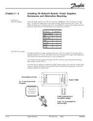
Typical application wiringNote that wiring instructions differ depending onthe main power.If the Load Center is operatingon 120VAC power:For compressor or valve control(L1 power leg is used)Take power for the controlled device from J4(normally closed contacts) or J5 (normally opencontacts) and from an available neutral connectionon the load center.For light control(L1 power leg is used)Connect one side of the light ballast to J3 and theother to an available neutral connection on the loadcenter.For fan or defrost control(L2 power leg is used)For fans, connect one side of the load to J1 andthe other side to an available neutral on the loadcenter.For defrost, connect one side of the load to J2and the other side to an available neutral on theload center.If the Load Center is operatingon 240VAC power:For compressor or valve control( L1 power leg is used)Take power for the controlled device from J4(normally closed contacts) or J5 (normally opencontacts) and from an empty L2 connection on theload center.For light control(L1 power leg is used)Connect one side of the light ballast to J3 and theother to an available L2 connection on the loadcenter.For fan or defrost control(L2 power leg is used)For fans, connect one side of the load to J1 andthe other side to an available L1 connector on theload center.For defrost, connect one side of the load to J2and the other side to an available L1 connector onthe load center.7
Load connections to defrost modules:On the defrost module, connections for the loadsare found as vertical pairs of spade connectors inthe upper left quadrant of the board. From left toright, these pairs are for Load 3 (individual terminalslabeled T2 and T5), Load 2 (T1 and T4), andLoad 1 (T3 and T6). The lower connector in eachpair is the L1 leg, and the upper connector is the L2leg, for that load.1. Connect the load wires to the appropriate pair ofL1-L2 spade connectors on the defrost module.2. Connect the neutral lines from the loads to spadeconnectors on the neutral bus on the load center.Addressing the defrost moduleDefrost modules must be addressed using the IDdip switch in the lower left quadrant of the module.With both switches down (OFF), the address valuewill be 0, the correct address for the first module. Asecond module would be addressed by placingswitch 1 up (ON) and switch 2 down (OFF). Whenthe module is correctly connected to the load centerand properly addressed, the red “TX” (transmit)and yellow “RX” (receive) LED’s will blink,indicating that there is successful communicationwith the load center.Troubleshooting:If the TX LEDdoes not blink, check the position ofthe ID dip switches.Software requirementsInstallation of a defrost module does not affectthe <strong>Degree</strong> <strong>Master</strong>’s software or require additionalprogramming. Defrost loads connected to themodule will be turned on when the fixture’s defrostcycle begins.module. Duplicating the power wiring can resultin damage to the defrost module.a. If you have used screw terminal strip on module#1 for incoming power, jumper the screwterminals on module #1, observing polarity, tothe screw terminals on module #2,or, if not,b. Jumper from spade connectors J3 (L1) and J4(L2) of module #1 to screw terminal strip P2(L1, L2) of module #2,orc. Jumper from spade connectors J3 (L1) and J4(L2) of module #1 to spade connectors J3 (L1)and J4 (L2) of module #2.4. Connect the neutral lines from the loads to to theterereneutral power strip on the load center.5. Follow the instructuctions at left under “Loadconnections to defrost modules” to connectmodule #2 to its loads.6. Address module #2 by setting switch 1 on theID dip switch up (ON) and switch 2 down(OFF). This will give module #2 an addressvalue of 1.When both modules are correctly connected to theload center and properly addressed, both red “TX”(transmit) and yellow “RX” (receive) LED’s willblink, indicating successful communication withthe load center.Troubleshooting:If any of the TX or RX LED’s do not blink, checkthe settings on the ID dip switches. They should beas follows:Module #1: both switches down (OFF)Module #2: switch 1 up (ON), switch 2 down(OFF).Defrost module installation for threephase defrostThe <strong>Degree</strong> <strong>Master</strong> supports three phase defrostloads with installation of multiple defrost modules.To control a three phase defrost load, follow thesesteps:1. Connect a defrost module to the <strong>Degree</strong> <strong>Master</strong>using the procedure detailed on page 4.2. Connect a second defrost module using the P1connector of the first defrost module.3. Use one (and only one) of the following optionsto provide load power to the second defrost9
Anti-sweat heater moduleThe <strong>Degree</strong> <strong>Master</strong> anti-sweat heater (ASH)module allows the load center to control up to threeanti-sweat loads.Power connections for ASH modulesThe ASH module requires 120VAC (2 wires)power derived from the load center. If the loadcenter and ASH module were purchased together,power connections will have been pre-wired at thefactory. If this is not the case, take these steps toinstall an ASH module:1. Turn off power to the <strong>Degree</strong> <strong>Master</strong> load center.2. Connect J1 of the ASH module to P2 on the loadcenter or to the expansion connector on anotherauxiliary module connected to the load center.3. Use one (and only one) of the following optionsto provide load power to the ASH module.Duplicating the power wiring can result indamage to the ASH module.a. Jumper from the ASH module’s J9 spade connector(L1) to an open connector on the L1 powerstrip of the load center or, if there is a previousauxiliary defrost module, to the module’s J3 spadeconnector (L1).orb. Use the screw terminal strip of the ASH module (P3)to power it, connecting L1 and neutral, according tothe labeling, to appropriate locations on the loadcenter.4. Jumper from the ASH module’s neutral powerconnection (either the J3 spade connector or theneutral screw terminal connection) to an availablespade connector on the load center’s neutral powerstrip.Load connections for ASH modulesConnect L1 and neutral wires from each anti-sweatheater load to the appropriately labeled terminals onthe ASH module for ASH1, ASH2, and ASH3.10
Echelon communicationsThe <strong>Degree</strong> <strong>Master</strong> uses the Echelon FTT-10<strong>net</strong>work protocol. To insure good <strong>net</strong>work functionand communications, always adhere to the specificationsgiven in this section.Echelon <strong>net</strong>worksThis section gives the cable type and distancelimitations for two Echelon-supported <strong>net</strong>workconfigurations: the FTT-10 star <strong>net</strong>work and theFTT-10 double-terminated daisy-chain <strong>net</strong>work.The star variation is recommended because it offersmore configuration flexibility. Whichever type of<strong>net</strong>work configuration you choose, adherence to theEchelon guidelines is required.It is strongly recommended that installationdrawings reflect your chosen <strong>net</strong>work layout andthat installing contractors be required to observethe configuration, cable type, and distance limitationsspecified. A copy of the installation drawingsshould be displayed on site to make <strong>net</strong>worktroubleshooting easy.Network routing should also always be documentedand posted on site for the use of maintenancepersonnel.Resistor <strong>net</strong>work terminationThe Echelon <strong>net</strong>work requires inclusion of atermination resistor. The value and location of thetermination resistor depends on <strong>net</strong>work configuration.Network specificationsSingly-terminated star configurationFTT-10 <strong>net</strong>workThe singly-terminated FTT-10 star configruration<strong>net</strong>work branches in various directions from acentral location (the hub). Each branch is a daisychainof load centers proceeding from one fixtureto another. A maximum of four branches from asingle <strong>net</strong>work hub is recommended.The star configurations requires the hub of thestar to be within ten feet of the <strong>net</strong>work managementdevice.Total <strong>net</strong>work length (star <strong>net</strong>work)The total length of <strong>net</strong>work cable in the <strong>net</strong>workis limited to 1600 feet (500 meters).Maximum node-to-node distance (star <strong>net</strong>work)The maximum distance between nodes on the<strong>net</strong>work is limited to 1300 feet (400 meters).Doubly-terminated daisy-chain configurationFTT-10 <strong>net</strong>workThe doubly-terminated FTT-10 daisy-chainconfigruration <strong>net</strong>work allows greater distance tobe run from the <strong>net</strong>work management controller,but requires that all nodes be connected in a singledaisy-chained cable run.This configuration allows easy isolation of the<strong>net</strong>work segments. Signal strength is greaterbecause there are fewer branch ends to cause signalreflections on the <strong>net</strong>work.Network cable type (doubly terminated)Network cable can be 16AWG Belden #8471(non-plenum) or Belden #85102 (plenum).Total <strong>net</strong>work length (doubly terminated)The total length of <strong>net</strong>work cable in the <strong>net</strong>workis limited to 8800 feet (2700 meters).Maximum node-to-node distance (doublyterminated)The maximum distance between nodes on the<strong>net</strong>work is limited to 1600 feet (500 meters) withBelden #85102 cable, and to 2200 feet (700meters) with #8471 cable.Avoid trouble -- Build a strong <strong>net</strong>work:1. Make sure there are no stray strands of wirewhere connectors are crimped on. Stray strandscan cause crosstalk.2. After you’ve attached a connector, hold theconnector and tug firmly on the cable to makecertain the crimp is secure.3. Make sure termination resistors are of correctsize and located properly on the <strong>net</strong>work.Network cable type (star <strong>net</strong>work)Network cable can be 16AWG Belden #8471(non-plenum) or Belden #85102 (plenum).11
Terminal stripFor maximum <strong>net</strong>work integrity, use ascrew terminal strip for connectionsbetween the <strong>net</strong>work manager and <strong>Degree</strong><strong>Master</strong> load centers.NetworkManager<strong>Degree</strong> <strong>Master</strong><strong>Degree</strong> <strong>Master</strong><strong>Degree</strong> <strong>Master</strong><strong>Degree</strong> <strong>Master</strong><strong>Degree</strong> <strong>Master</strong>LonWorksconnection onNetwork Manager<strong>Degree</strong> <strong>Master</strong><strong>Degree</strong> <strong>Master</strong>Install a 51 ohmresistor acrossthis connection.NOTES:1. Maximum total <strong>net</strong>work cable length is 1600 feet2. All <strong>net</strong>work cable must be Belden #8471 orBelden #85102.3. Network connections have no polarity.<strong>Degree</strong> <strong>Master</strong><strong>Degree</strong> <strong>Master</strong>A singly-terminated <strong>Degree</strong> <strong>Master</strong> <strong>net</strong>workA doubly-terminated <strong>Degree</strong> <strong>Master</strong> <strong>net</strong>work120 Ohm 1/4 wattresistor across LONconnector<strong>Degree</strong> <strong>Master</strong>NetworkManager<strong>Degree</strong> <strong>Master</strong>NOTES:1. Maximum total <strong>net</strong>work cable length is 8800 feet2. All <strong>net</strong>work cable must be Belden #8471 or Belden #85102.3. Network connections are not polarity sensitive.LonWorksconnection onNetwork Manager<strong>Degree</strong> <strong>Master</strong>120 Ohm 1/4 wattresistor across LONconnector<strong>Degree</strong> <strong>Master</strong><strong>Degree</strong> <strong>Master</strong><strong>Degree</strong> <strong>Master</strong><strong>Degree</strong> <strong>Master</strong>12
The <strong>Degree</strong> <strong>Master</strong> hand-held remotecontrolThe hand-held remote allows both interrogationand programming of <strong>Degree</strong> <strong>Master</strong>s.A quick tour of the remoteSurrounding the number key area, the remote hasfour special functionalareas; clockwise from thetop, they are:1.VIEW, with these keys:[STATUS][LOADS][MISC]2.FUNCTIONS, withthese keys:[NORM OP][CASE OFF][CASE CLN][EMRG D][ALRM OVRD]3.SETPOINTS, withthese keys:[TEMP][DEFR][ALARM][ASH][LIGHT]4.SETUP, with thesekeys:[INPUTS][CONFIG]The number key area, inaddition to 1-0 and +/- keys, also contains someimportant special function keys:The scroll navigation keys, surrounding the[REPEAT] key;[ESC][ENTER][CONNECT]In this manual, we will use words to representthe arrows that actually appear on the keys. Theyellow [UP] and [DOWN] keys are used to scrollthrough the displayed fields.[ RIGHT] has thesame effect as [DOWN], and [LEFT] has the sameeffect as UP. The REPEAT key will re-scroll thecurrent display from the beginning. When scrollingthe display or programming with the remote, it isessential to wait until the display has completelyfinished scrolling and is at rest before makingentries. The <strong>Degree</strong> <strong>Master</strong> will not respond toentries made while the display is scrolling.The VIEW keysSTATUSThe [STATUS] key will first display the wordsCASE STATUS, then the default temperature. Thedefault temperature can be programmed to beCTRL TEMP (a circuit control setting provided bythe <strong>net</strong>work manager), CASE TEMP (a temperaturevalue from a sensor in the case), or PRODTEMP (a value provided by a product temperaturesensor in the case). By using the down arrow, theother two fixtures temperatures will be displayed inthe order programmed.Here are all of the status displays in the orderthat they will appear using the down arrow, andtheir meanings:MAX PROD TEMPthe highest temperature reached since midnightor the last resetALRM STATcurrent alarm conditions for the fixtureNO AL there are no active alarmsHI T there is a high temperature alarmLO T there is a low temperature alarmDCHdischarge air temperatureRTNreturn air temperatureDEFR TERMthe temperature at the defrost termination sensorEVAP INthe temperature of the evaporator at its inletEVAP OUTthe temperature of the evaporator at its outletSUPR HEATthe evaporator superheat, calculated as thedifference between the EVAP OUT and EVAP INsensors.LOADSThe [LOADS] key reveals data for the <strong>Degree</strong><strong>Master</strong>’s controlled loads (outputs). Each of the14
loads can have one of two states -- ON or OFF.Here are the displays in the order that they willappear after pressing the [LOADS] key on theremote:REFRthe status of the refrigeration output; whether the<strong>Degree</strong> <strong>Master</strong> is calling for refrigeration to beon or off.DEFRwhether the fixture defrost output is on or off.FANwhether the fixture fan output is on or off.LGHTwhether the fixture light output is on or off.ASHthe percentage of time the anti-sweat heaters areon. NOTE: the % sign is represented by a P. Thisvalue will read 100P if there is no ASH modulepresent.REFR OVRDwhether or not refrigeration control is in override.If you push [ENTER] while in this field,you can select override of DEGREE MASTERcontrol by scrolling down from “NONE” to“ON” or “OFF” and pushing [ENTER] again.DEFR OVRDwhether or not defrost control is in override. Ifyou push [ENTER] while in this field, you canselect override of DEGREE MASTER control byscrolling down from “NONE” to “ON” or “OFF”and pushing [ENTER] again.FAN OVRDwhether or not fan control is in override. If youpush [ENTER] while in this field, you can selectoverride of DEGREE MASTER control byscrolling down from “NONE” to “ON” or “OFF”and pushing [ENTER] again.LGHT OVRDwhether or not light control is in override. If youpush [ENTER] while in this field, you can selectoverride of DEGREE MASTER control byscrolling down from “NONE” to “ON” or “OFF”and pushing [ENTER] again.ASH OVRDwhether or not anti-sweat heater control is inoverride. If you push [ENTER] while in thisfield, you can select override of DEGREEMASTER control by scrolling down from“NONE” to “ON” or “OFF” and pushing [EN-TER] again.MISCThe information shown in the MISC display isunique to each <strong>Degree</strong> <strong>Master</strong> load center. It alsovaries with the version of software installed. Hereare the displays in the order that they will appearafter pressing the MISC key on the remote:DEWP TEMPthe calculated dew point temperature receivedfrom the <strong>net</strong>work manager.SUCT TEMPsuction temperature received from the <strong>net</strong>workmanager.DOWthe day of the week received from the <strong>net</strong>workmanager.TIMEthe time of day received from the <strong>net</strong>workmanager.SUBNthe sub<strong>net</strong> address (used by <strong>Degree</strong> <strong>Master</strong>service technicians).NODEthe node number of the particular <strong>Degree</strong><strong>Master</strong> on the <strong>net</strong>work.VERSIONthe version number of the <strong>Degree</strong> <strong>Master</strong>software installed.15
Programming and changingsettingsConnecting to the <strong>Degree</strong> <strong>Master</strong>To make any changes to the settings or programmedfunctions of the <strong>Degree</strong> <strong>Master</strong>, you mustfirst connect to the device using the followingprocedure:1. Push [CONNECT]. The display responsd“FOR CNX COPY NUM nnnn” where “nnnn”is a four digit numeral.2. Push [ENTER]. The first digit of the displayednumeral blinks.3. Enter the four digit number “nnnn” you saw instep 1 above.4. Push [ENTER]. You now have programmingaccess to the device; the first status displayappears again.You can now move to all the areas where programmingentries are possible. If at any time threeminutes pass without any key being pushed on theremote, you will be disconnected.Programming inputsIn order to program an input, it is necessary tospecify its channel and type, and to enter anoffset if one is required to adjust the accuracy ofthe sensor. Let’s define those terms:CHANNELthe dedicated pathway sensor informationtakes as it enters and is processed by the loadcenter. The channel will have a number from00 to 05.TYPEthe type of input:NONE there is no sensor for this inputELM the sensor is an Elm sensorDIG the sensor is a digital (on-off) sensorTP1the sensor is a Danfoss TP1 sensorTP2 the sensor is a Danfoss TP2 sensorOFFSETa number of degrees from 00 to 99 that isadded to or subtracted from the sensor valueby the <strong>Degree</strong> <strong>Master</strong> to fine tune sensorreadings.To change an input’s setup, use the followingprocedure1. Connect to the <strong>Degree</strong> <strong>Master</strong> using the proceduredescribed at left.2. Push the [INPUTS] key. “SETUP INPUTS” willscroll across the display. You will then see themessage “FOR PROD SNSR PUSH ENTR.”You can set up the product sensor or use the upand down arrows to move to another sensor.Using the down arrow, the sensors will appear inthis order:PRODproduct temperature sensorDCHdischarge air temperature sensorRTNreturn air temperature sensorDEFRdefrost termination temperature sensorEVAP INevaporator inlet temperature sensorEVAP OUTevaporator outlet temperature sensorWe will assume for the purpose of example thatyou wish to set up the product temperaturesensor.3. Push [ENTER] to select the product sensor. Thedisplay responds with “CHAN nn” where nn is atwo-digit numeral. Only the numeral remains onthe display. (Remember, if at any time you needto refresh your memory, press repeat to reviewthe entire message.) If the displayed channel isthe correct channel for the product sensor, go tostep 5. If you need to change the channel, press[ENTER], and the first digit of the channelnumber begins to blink. You can key in a numberfrom 0-9 from the numeric pad or you can usethe up and down arrow keys to change thenumber. When the number is as you want, moveto the right digit by using the right arrow key.Adjust this digit in the same manner.4. When the channel number is correct, press[ENTER].5. In the same manner, use the up and down arrowkeys to scroll to the other programmable fields(TYPE, OFFS) and make any needed changes.6. Push [ESC] to exit to the main input.7. Use the arrow keys to move to the next input16
needing changes. Make the changes as detailedabove.Programming system configurationSystem setup is accomplished after connectingto the <strong>Degree</strong> <strong>Master</strong>, then pushing the [CONFIG]key. Configuration options are as follows:REFR CTRLNONENo refrigeration control is programmed.MFGR not yet implementedEEV not yet implementedEPR not yet implementedCYCL on-off controlVALVE TYPENONE no valve is controlledMFGR not yet implementedPULS not yet implementedSTEPSOLNnot yet implementedthe controlled valve is either aliquid line or suction stop solenoid.VALVE POLARITYEOFF the valve is normally closedEON the valve is normally openUSE FAN CYCLE CTRLSets fans to be turned off if a selected sensor isat too high a temperature. Choose YES or NO.USE FAN/ DEFR RLY FORFANS the relay controls fansDEFR the relay controls defrostPULSE PERIODnot yet implementedSTEP RATE not yet implementedMAX STEP not yet implementedSTEP HYSTERESISnot yet implementedSTEP INIT RNGnot yet implementedDOW the day of the weekTIME the time of dayDFLT TEMP DISPPROD product sensor is default displayCTRL control sensor is default displayCASE case sensor is default displayDUAL TEMP MODEMED for medium temperature operationLOW for low temperature operationProgramming setpointsSetpoint programming and changes are accomplishedby using the keys in the setpoints area of17the remote control. The five buttons and theirassociated setpoints are as follows:[TEMP]: Temperature setpointsAfter pushing the [TEMP] button, the confirmingmessage “SETUP REFRIG’ appears,followed by the first parameter, “CUT IN” andits current value. As for any parameter, if youwish to change the setting, push [ENTER]when the value appears, and the display willbegin to flash. Use the number keys to put inthe new setting. The other parameters are:CUT INthe temperature at which refrigeration will bestarted.DEAD BANDthe number of degrees differential between cutin and cut out.SUPR HEATthe temperature differential to maintain acrossthe evaporator, between sensors EVAP IN andEVAP OUT.MIN OFF TIMEthe length of time that refrigeration mustremain off before being turned on.FAN CYCL SETP(active only if there is a “YES” answer to“USE FAN CYCL TEMP” in configuration)fans will be off at and above this temperature.MED TEMP OFFSthe offset by which temperature setpoint andalarm limits will be raised for operation in themedium temperature range in dual temperatureoperation.[DEFR]: Defrost setpointsThe parameters are:TERM TYPETIME terminates on time aloneTEMP terminates on time and tempOPEN terminates on open digital sensorCLSDF termniates on closed digital sensorSTRT TIMEThe start time for the first defrost. If more thanone defrost is scheduled, they will be evenlyspaced throughout the day.NUM PER DAYThe number of defrosts per day.MAX TIMEthe maximum defrost time, in minutes.MIN TIMEthe minimum defrost time, in minutes.
TERM TEMPthe termination temperature.DRIP DOWN DLYthe time in minutes to wait after defrostbefore resuming refrigeration.FAN STRT SETPthe temperature at which fans start afterdefrost termination.FAN STRT DLYThe maximum time fans will delay afterdefrost termination regardless of temperature.POST DEFR ALRM DLYthe time during which alarms will not beallowed after termination of defrost.REFR VALV IN DEFRCLSD the valve is closed during defrostOPEN the valve is open during defrostFAN IN DEFRNORM fan will operate normally duringdefrost.OFF fan will be off during defrost.LGHT IN DEFRNORM lights will operate normally duringdefrost.OFF lights will be off during defrost.ASH IN DEFRNORM anti-sweat heaters will operatenormally during defrost.OFF anti-sweat heaters will be offduring defrost.[ALARM]: Alarm setpointsThe parameters are:HIGH CASE TEMPthe high case temperature for alarm.LOW CASE TEMPthe low case temperature for alarm.HIGH PROD TEMPthe high product temperature for alarm.LOW PROD TEMPthe low product temperature for alarm.ALRM DLYthe number of minutes an alarm temperatureis exceeded before an alarm occurs.CASE CLN DLYthe number of minutes during which noalarms will be generated during casecleaning.LGHT IN ALRM18NORM anti-sweat heaters will operatenormally during alarm conditions.OFF anti-sweat heaters will be offduring alarm conditions.ASH IN ALRMNORM lights will operate normally duringalarm conditions.OFF lights will be off during alarmconditions.[ASH]: Anti-sweat heater setpointsThe parameters are:DEWP HIGH SETPthe high dewpoint setpoint.DEWP LOW SETPthe low dewpoint setpointASH1 MIN DUTYthe minimum percentage of its 7-secondduty cycle that ASH1 will runASH1 MAX DUTYthe maximum percentage of its 7-secondduty cycle that ASH1 will runThe same settings are made for ASH2 and ASH3.[LIGHT]: Lighting setpointsThe parameters are:SUN ON TIMEThe time of day at which the fixture lightsare wanted on on Sunday.SUN OFF TIMEThe time of day at which the fixture lightsshould turn off on Sunday.The same settings are made for the other days ofthe week.
Special functionsThe fixture can be put in several modes ofoperation with the handheld remote. These functionsof the remote should be used with care.[NORM OP]: Normal operationThis button returns the fixture to normaloperation under control of the <strong>Degree</strong> <strong>Master</strong> asprogrammed.[CASE OFF]: Case offThis button turns the fixture off. All functions,refrigeration, fans, lights, defrost, and anti-sweatheaters, will be off until the [NORM OP] key ispushed.[CASE CLN]: Case cleaningAll case functions will be turned off to allowcleaning. Fucntions will remain off until [NORMOP] is pushed. If [NORM OP] is not pushed, and“CASE CLN DLY” expires, an alarm will begenerated.[EMERG D]: Emergency defrostA defrost (with the same termination parameters asconfigured for normal defrosts) will be initiated.[ALRM OVRD]: Alarm overrideAlarms from the fixture will be turned off untilturned back on with this key. The alarm LED willflash during the override.Using the display’s buttonsThe buttons on the digital display can be usedto interrogate the <strong>Degree</strong> <strong>Master</strong> and access servicefunctions. The buttons can operate in three modes:status, aux functions, and service.Status modeIn this mode, the upper button has the samefunction as the [REPEAT] key on the remotecontrol. Pushing the upper button will cause thedisplay to repeat the label for the present reading.The lower button has the same function as thedown arrow key on the remote. It will move thedisplay to the next field.The fields that can be seen in this mode are:PROD TEMPCASE TEMPCTRL TEMPMAX PROD TEMP19ALRM STATDCHRTNDEFR TERMEFAP INEVAP OUTSUPR HEATAux functions modeTo enter the aux functions mode, push and holdthe upper button for five seconds. In this mode anumber of functions can be activated:CASE CLNNORM OPEMRG DEFRCASE OFFALRM OVRDDUAL TEMPCHANGE TO [xxx] TEMP(dual temp function)this could read CHANGE TO LOW TEMPor CHANGE TO MED TEMP, depending onthe range in which the fixture is currentlyoperating.On the display, each of the functions is followedby the letters “HLD” preceded by an uparrow. If you press and hold the upper buttonduring this display, the up arrow will change to anasterisk (*) and the <strong>Degree</strong> <strong>Master</strong> will enter theselected state. In the case of CASE CLN, CASEOFF, and ALRM OVRD, the case will not berestored to normal function until NORM OP isactivated. In the case of EMRG DEFR, the defrostwill be terminated when the case reaches defrosttermination temperature or when the maximumdefrost time has elapsed. For DUAL TEMP, press[ENTER], then the up arrow, then [ENTER] againto change modes.Service modeTo enter the service mode, push and hold bothbuttons for 3 seconds. When the <strong>Degree</strong> <strong>Master</strong>enters the service mode, the display changes to“↑RS↓”. Now the butttons have very differentfunctions. The upper button will reset the system;the lower button will activate the service button,which allows the host controller to recognize the<strong>Degree</strong> <strong>Master</strong> as a node. When either button ispressed for these functions, the arrow changes toan asterisk as confirmation.
WARRANTYHEREINAFTER REFERRED TO AS MANUFACTURERFOURTEEN MONTH WARRANTY. MANUFACTURER’S PRODUCT IS WARRANTED TO BE FREE FROMDEFECTS IN MATERIAL AND WORKMANSHIP UNDER NORMAL USE AND MAINTENANCE FOR APERIOD OF FOURTEEN MONTHS FROM THE DATE OF ORIGINAL SHIPMENT. A NEW OR REBUILTPART TO REPLACE ANY DEFECTIVE PART WILL BE PROVIDED WITHOUT CHARGE, PROVIDED THEDEFECTIVE PART IS RETURNED TO MANUFACTURER. THE REPLACEMENT PART ASSUMES THEUNUSED PORTION OF THE WARRANTY.This warranty does not include labor or other costs incurred for repairing, removing, installing, shipping,servicing, or handling of either defective parts or replacement parts.The fourteen month warranty shall not apply:1. To any unit or any part thereof which has been subject to accident, alteration, negligence, misuse orabuse, operation on improper voltage, or which has not been operated in accordance with themanufacturer’s recommendation, or if the serial number of the unit has been altered, defaced, or removed.2. When the unit, or any part thereof, is damaged by fire, flood, or other act of God.3. Outside the continental United States.4. To labor cost for replacement of parts, or for freight, shipping expenses, sales tax or upgrading.5. When the operation is impaired due to improper installation.6. When installation and startup forms are not properly complete or returned within two weeks after startup.THIS PLAN DOES NOT COVER CONSEQUENTIAL DAMAGES. Manufacturer shall not be liable under anycircumstances for any consequential damages, including loss of profit, additional labor cost, loss ofrefrigerant or food products, or injury to personnel or property caused by defective material or parts or forany delay in its performance hereunder due to causes beyond its control. The foregoing shall constitutethe sole and exclusive remedy of any purchases and the sole and exclusive liability of Manufacturer inconnection with this product.The Warranties are Expressly in Lieu of All Other Warranties, Express of Implied and All OtherObligations or Liabilities on Our Part. The Obligation to Repair or Replace Parts or ComponentsJudged to be Defective in Material or Workmanship States Our Entire Liability Whether Based on Tort,Contract or Warranty. We Neither Assume Nor Authorize Any Other Person to Assume for Us AnyOther Liability in Connection with Our Product.MAIL CLAIM TO:Hill PHOENIXDisplay Merchandisers1925 Ruffin Mill RoadColonial Heights, VA 23834804-526-4455Hill PHOENIXRefrigeration Systems &Electrical Distribution Products709 Sigman RoadConyers, GA 30013770-285-32001/98
WarningMaintenance & Case CareWhen cleaning cases the following must be performedPRIOR to cleaning:To avoid electrical shock, be sure all electric power isturned off before cleaning. In some installations, morethan one switch may have to be turned off to completelyde-energize the case.Do not spray cleaning solution or water directly on fanmotors or any electrical connections.All lighting receptacles must be dried off prior to insertionand re-energizing the lighting circuit.Please refer to the Use and Maintenance section of this installation manual.ASH1080804-526-44551925 Ruffin Mill Road, Colonial Heights, VA 23834Due to our commitment to continuous improvement all specifications are subject to change without notice.Hill PHOENIX is a Sustaining Member of the American Society of Quality.CRMA endorsedVisit our web site at www.hillphoenix.com