sentronic oil contro.. - icemeister.net
sentronic oil contro.. - icemeister.net
sentronic oil contro.. - icemeister.net

Create successful ePaper yourself
Turn your PDF publications into a flip-book with our unique Google optimized e-Paper software.
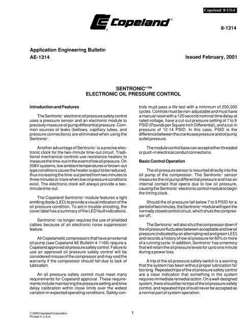
Copeland 8-1314<br />
®<br />
®<br />
8-1314<br />
Application Engineering Bulletin<br />
AE-1314 Issued February, 2001<br />
SENTRONIC + <br />
ELECTRONIC OIL PRESSURE CONTROL<br />
Introduction and Features<br />
The Sentronic + electronic <strong>oil</strong> pressure safety <strong>contro</strong>l<br />
uses a pressure sensor and an electronic module to<br />
precisely measure <strong>oil</strong> pump differential pressure. Common<br />
sources of leaks (bellows, capillary tubes, and<br />
pressure connections) are eliminated when using the<br />
Sentronic + .<br />
Another advantage of Sentronic + is a precise electronic<br />
clock for the two-minute time-out circuit. Traditional<br />
mechanical <strong>contro</strong>ls use resistance heaters to<br />
measure the time-out in the event of low <strong>oil</strong> pressure. On<br />
208V systems, low ambient temperatures or brown-out<br />
type conditions cause the heater output to be reduced,<br />
thus increasing the time-out period from two minutes to<br />
three minutes or more when low <strong>oil</strong> pressure conditions<br />
exist. The electronic clock will always provide a twominute<br />
time-out.<br />
The Copeland Sentronic + module features a light<br />
emitting diode (LED) to provide a visual indication of the<br />
<strong>oil</strong> pressure condition. To aid in trouble-shooting, the<br />
cover label has a summary of the LED fault indications.<br />
Sentronic + no longer requires the use of shielded<br />
cables because of an electronic noise suppression<br />
feature.<br />
All Copelametic compressors that have an external<br />
<strong>oil</strong> pump (see Copeland AE Bulletin 4-1166) require a<br />
Copeland approved <strong>oil</strong> pressure safety <strong>contro</strong>l. Failure to<br />
use an approved <strong>oil</strong> pressure safety <strong>contro</strong>l will be<br />
considered misuse of the compressor and may void the<br />
warranty if the compressor should fail due to lack of<br />
lubrication.<br />
An <strong>oil</strong> pressure safety <strong>contro</strong>l must meet many<br />
requirements for Copeland approval. These requirements<br />
include maintaining the pressure setting and time<br />
delay calibration within close limits over the widest<br />
variation in expected operating conditions. Safety <strong>contro</strong>ls<br />
must pass a life test with a minimum of 200,000<br />
cycles. Controls must be non-adjustable and must have<br />
a manual reset with a 120 second nominal time delay at<br />
rated voltage, have a cut-out pressure setting of 7 to 9<br />
PSID (Pounds per Square Inch Differential), and a cut-in<br />
pressure of 12-14 PSID. In this case, PSID is the<br />
difference between the crankcase pressure and <strong>oil</strong> pump<br />
outlet pressure.<br />
The module <strong>contro</strong>l base can accept either threaded<br />
or push-in electrical conduit connections.<br />
Basic Control Operation<br />
The <strong>oil</strong> pressure sensor is mounted directly into the<br />
<strong>oil</strong> pump of the compressor. The Sentronic + sensor<br />
measures the <strong>oil</strong> pump differential pressure and has an<br />
internal contact that opens due to low <strong>oil</strong> pressure,<br />
causing the Sentronic + electronic <strong>contro</strong>l module to begin<br />
the timing clock.<br />
Should the <strong>oil</strong> pressure fall below 7 to 9 PSID for a<br />
period of two minutes, the Sentronic + module will open the<br />
normally closed <strong>contro</strong>l circuit, which shuts the compressor<br />
off.<br />
The Sentronic + will also shut the compressor down if<br />
the <strong>oil</strong> pressure fluctuates between acceptable and low <strong>oil</strong><br />
pressure (indicated by an alternating red and green LED)<br />
and records a history of low <strong>oil</strong> pressure for 60% or more<br />
of a running cycle. In addition, Sentronic + has a memory<br />
that will retain the <strong>oil</strong> pressure levels for up to one minute<br />
during a power loss.<br />
A trip of the <strong>oil</strong> pressure safety switch is a warning<br />
that the system has been without proper lubrication for<br />
too long. Repeated trips of the <strong>oil</strong> pressure safety <strong>contro</strong>l<br />
are a clear indication that something in the system<br />
requires immediate remedial action. On a well-designed<br />
system, there should be no trips of the <strong>oil</strong> pressure safety<br />
<strong>contro</strong>l, and repeated trips should never be accepted as<br />
a normal part of system operation.<br />
© 2000 Copeland Corporation<br />
Printed in U.S.A.<br />
1
Copeland 8-1314<br />
Sentronic + Control Module<br />
In addition to the normally closed (N.C.) contact used<br />
for compressor shutdown, the Sentronic + has a normally<br />
open (N.O.) contact which can be used in an alarm circuit<br />
(See Figure 5).<br />
The Single Pole Double Throw (S.P.D.T.) contact of<br />
Sentronic + can be electrically isolated from the <strong>contro</strong>l<br />
circuit power supply and used to <strong>contro</strong>l a different<br />
voltage (See Figure 3).<br />
Installation<br />
All Copeland compressors with external <strong>oil</strong> pumps<br />
shipped after September 1986 have a plug fitting in the <strong>oil</strong><br />
pump for mounting the sensor. The external <strong>oil</strong> pump is<br />
designed to accept either the Sentronic + sensor or a<br />
capillary tube for the traditional mechanical <strong>oil</strong> pressure<br />
<strong>contro</strong>l.<br />
Removing the cover on the module is accomplished<br />
by gently lifting two locking tabs on the lower corners of<br />
the cover and pulling the lower edge of the cover away<br />
from the base. Refer to figure 1.<br />
Figure 2<br />
Installation of the cover is accomplished by hooking<br />
the top of the cover down on the three tabs on the top of<br />
the module base and swinging the cover back into<br />
position until the cover release tabs latch into place.<br />
Refer to figure 2.<br />
Installing the Sensor<br />
1. Remove the plug fitting from the <strong>oil</strong> pump housing<br />
(new installations). Discard the copper washer from under<br />
the head of the plug fitting.<br />
2. Install the new O ring into the groove around the<br />
sensor. Note: If applicable, replace the aged O ring<br />
with the new one supplied in the kit. Use refrigeration<br />
<strong>oil</strong> to pre-lubricate the O ring before installation. Use care<br />
not to cut the O ring.<br />
3. Use the new copper washer. Do not reuse the copper<br />
washer removed with the plug fitting.<br />
4. Screw the sensor into the pump body. Torque the<br />
sensor to 60-65 Ft.-Lb.<br />
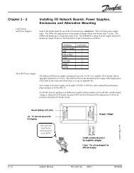
Installing the Module<br />
1. When using the bracket above the <strong>oil</strong> pump, use the<br />
supplied 10-32 pan head slotted screws with washers.<br />
Alternatively, four holes have been incorporated in the<br />
module base to provide the option of remote mounting.<br />
Refer to figure 7. The maximum screw length is .265”<br />
plus bracket thickness. Longer screws could damage the<br />
circuit board.<br />
Figure 1<br />
2. Plug the cable from the module into the end of the<br />
sensor. Care should be taken to route the cable away<br />
from current carrying conductors.<br />
© 2000 Copeland Corporation<br />
Printed in U.S.A.<br />
2
Excessive hi-potting can cause damage to the<br />
Sentronic + module. If hi-potting is required, we recommend<br />
it be limited to a single time.<br />
Static electricity discharges from electrostatic painting<br />
can damage the Sentronic + module. We recommend<br />
that the module not be mounted until such painting is<br />
completed.<br />
The module location and conduit lengths should be<br />
chosen to avoid bending of the conduit beyond its normal<br />
range of flexibility.<br />
Remote Mounting<br />
The Sentronic + module sends a low voltage signal to<br />
determine whether the sensor circuit is opened or closed.<br />
When the Sentronic + module is mounted on the compressor,<br />
the sensor will normally experience no disturbances<br />
from nearby electrical sources. While the Sentronic + is<br />
not particularly susceptible to Electromag<strong>net</strong>ic Field<br />
(EMF) interference, it is wise to keep the cable away from<br />
other current carrying conductors.<br />
Grounding<br />
The Sentronic + plus has been designed with a plastic<br />
case, and does not require a ground connection. A ground<br />
screw is provided on the terminal strip for those installations<br />
utilizing a ground wire in the conduit.<br />
Sentronic + Specifications<br />
Cut-Out<br />
Cut-In<br />
Time Delay<br />
Sensor Torque<br />
Max Control<br />
Max Control<br />
Max Inrush<br />
Max Inrush<br />
Installing external timer<br />
7-9 PSID<br />
12-14PSID<br />
120 seconds + 15 seconds<br />
60-65 Ft.-Lb.<br />
375 VA; 120V<br />
500 VA; 240V<br />
1600 VA; 120 V<br />
3000 VA; 240 V<br />
Caution: An electronic timer may be placed in<br />
series with the compressor contactor to force a delay<br />
before each start and prevent possible short cycling.<br />
The timer must be located so it also prevents the<br />
Sentronic + from energizing during the timing period.<br />
SOME INEXPENSIVE TIMERS MAY “LEAK” ENOUGH<br />
POWER WHILE “TIMING-OUT,” TO ENERGIZE THE<br />
SENTRONIC + EVEN THOUGH THERE MAY NOT BE<br />
ENOUGH “LEAKAGE” TO CLOSE THE COMPRES-<br />
SOR CONTACTOR. THIS CAN CAUSE A PREMATURE<br />
SENTRONIC + TRIP.<br />
If there is doubt, the circuit should be checked<br />
before placing it in operation.<br />
Standard Control Circuits<br />
Copeland 8-1314<br />
Both Figures 4A (Sentronic + ) and 4B (previous<br />
Sentronic) show typical wiring connections and the<br />
similarity of Sentronic + and Sentronic <strong>oil</strong> pressure<br />
switches used on three-phase motor compressors.<br />
When the operating and limit <strong>contro</strong>ls are closed, the<br />
system is calling for the compressor to run. The electrical<br />
circuit for the Sentronic + module consists of a 240 V<br />
(120V) connection to the appropriate terminal and the<br />
jumper between 2 and “M” and the normally closed (N.C.)<br />
contact between “M” and “L”. The compressor contactor<br />
circuit is completed by the normally closed contact<br />
between “M” and “L”. If the module trips the circuit due to<br />
low <strong>oil</strong> pressure, the N.C. contact between “M” and “L”<br />
opens thereby opening the circuit of the compressor<br />
contactor and the module.<br />
Once the Sentronic + module has tripped, it must<br />
be manually reset to restore operation.<br />
Control with Alarm<br />
The alarm circuit as seen in Figure 5 will be<br />
activated when the Sentronic + trips on low <strong>oil</strong> pressure.<br />
The normally open (N.O.) contactor between “L” and “A”<br />
will be closed when the module trips thereby activating<br />
the alarm circuitry.<br />
The Current Sensing Relay Used With Compressor<br />
Inherent Motor Protectors:<br />
A compressor may exhibit nuisance trips if it has an<br />
inherent protector and experiences motor overheating.<br />
The use of a current-sensing relay allows the compressor<br />
to cycle on the internal inherent protector without affecting<br />
the operation of the Sentronic + .<br />
After an overload trip of a compressor with an<br />
inherent protector, the <strong>contro</strong>l circuit will still be<br />
closed and the Sentronic energized although the<br />
compressor motor is not operating. The two-minute<br />
timing circuit will activate due to a lack of <strong>oil</strong> pressure, and<br />
after the 120-second time delay; the <strong>oil</strong> pressure safety<br />
switch will trip. Even though the compressor motor cools<br />
sufficiently for the internal inherent protector to automatically<br />
reset, the compressor cannot start until the <strong>oil</strong><br />
pressure safety <strong>contro</strong>l is manually reset.<br />
This is normally not a problem since the compressor,<br />
if properly applied, will seldom if ever trip on the internal<br />
inherent protector. If it should happen to do so, the fact<br />
that a protector trip has occurred indicates that the<br />
system operation should be reviewed. However, on frozen<br />
food or other critical applications where a product loss<br />
may occur, if a compressor shutdown should occur during<br />
the night or a weekend when the equipment is unattended,<br />
it may be desirable to prevent a possible nuisance trip by<br />
means of a current sensing relay.<br />
© 2000 Copeland Corporation<br />
Printed in U.S.A.<br />
3
Copeland 8-1314<br />
The current sensing Relay is mounted on the load<br />
side of the contactor, senses by induction the full<br />
operating current of one phase of the motor, closes on a<br />
rise above 14 amps, and opens if the load current falls<br />
below 4 amps.<br />
Figure 6 uses a current relay (C.S.). When the<br />
current relay is not energized by motor current, its<br />
Normally Open (N.O.) contact opens the circuit that<br />
powers the Sentronic to avoid a nuisance trip.<br />
NOTE: On some 550 volt motor-compressors, it may<br />
be necessary to loop the current carrying wire so that it<br />
passes through the current sensing relay twice in order to<br />
increase the metered amperage to close the relay contacts.<br />
Using a Separate Control Voltage with the Sentronic +<br />
(Figure 3):<br />
To supply the Sentronic + with two separate voltages<br />
(compressor contactor c<strong>oil</strong> and module), remove the<br />
jumper between terminals “2” and “M.” In this diagram, the<br />
separate <strong>contro</strong>l voltage is supplied by “LL1” and “LL2.”<br />
The separate voltage powers the compressor contactor<br />
(CC) by means of a remote relay. When the remote relay<br />
is energized, requesting the compressor to run, its<br />
contact (RR), closes to deliver “LL1” voltage to the<br />
operating and limit contacts. If the contacts in the<br />
operating and limit circuit are closed, “LL1” voltage<br />
energizes the compressor contactor c<strong>oil</strong> (CC). When the<br />
compressor contactor closes, it provides the power,<br />
through a <strong>contro</strong>l circuit transformer (XFMR), to energize<br />
the Sentronic + . If the Sentronic + trips, its contact (“L” to<br />
“M”) in the “LL1-LL2” <strong>contro</strong>l circuit opens to de-energize<br />
the compressor contactor and stop the compressor. The<br />
Sentronic + contact (“L” to “A”) closes to energize an Alarm<br />
Relay (AR).<br />
Note that any A.C. voltage up to and including 240<br />
volts may be used. For line voltages greater than 240 V,<br />
a step-down transformer (circuit transformer XFMR in<br />
Figure 3) must be used.<br />
LED Interpretation<br />
To aid in troubleshooting an <strong>oil</strong> pressure problem, the<br />
Sentronic + has an LED as a visual aid. This section<br />
explains the information provided by the LED.<br />
LED Green<br />
Compressor has sufficient <strong>oil</strong> pressure.<br />
LED Red<br />
Compressor is experiencing insufficient <strong>oil</strong> pressure.<br />
Red/Green LED Alternating<br />
Compressor is experiencing erratic <strong>oil</strong> pressure<br />
indicating a possible system problem.<br />
No Light<br />
Control Circuit is not energized L or M for light circuit.<br />
The Current Sentronic+<br />
© 2000 Copeland Corporation<br />
Printed in U.S.A.<br />
Figure 3<br />
4
Start Up Procedure<br />
Copeland 8-1314<br />
© 2000 Copeland Corporation<br />
Printed in U.S.A.<br />
5
Copeland 8-1314<br />
Troubleshooting<br />
Approximate <strong>oil</strong> pressure can be measured in the<br />
field. Oil pumps are furnished with a Schrader valve<br />
mounted on the <strong>oil</strong> pump discharge port. To measure <strong>oil</strong><br />
pressure, subtract crankcase pressure from discharge <strong>oil</strong><br />
pressure.<br />
Checking the Installed Sentronic + Module<br />
Shut off the compressor. Unplug the sensor. Read<br />
the <strong>contro</strong>l voltage between the 240V (or 115V) terminal<br />
and the L (or 2 if separate <strong>contro</strong>l is used) terminal to<br />
verify power to the module.<br />
Start the compressor with the sensor unplugged.<br />
Recheck to make sure the module voltage is still present.<br />
After 120 seconds ± 15 seconds, the L-M contact should<br />
open and shut off the compressor.<br />
With the module off due to low <strong>oil</strong> pressure, wait two<br />
minutes and press the reset button. Lack of power after<br />
a reset may be due to an external time delay circuit.<br />
Checking the Sensor<br />
Unplug the sensor and, start the compressor. The<br />
Sentronic + module LED should be red. Simultaneously<br />
measure the <strong>oil</strong> pump differential pressure. Monitor the<br />
two terminals at the back of the sensor with an ohmmeter<br />
or continuity measuring set. If the differential pressure is<br />
below the range of 7 to 9 PSID, the sensor circuit should<br />
be open (no continuity, infinite resistance). If the pressure<br />
is above 12 to 14 PSID, the sensor circuit should be<br />
closed.<br />
Measure the differential pressure by subtracting the<br />
crankcase pressure from the <strong>oil</strong> pump outlet pressure.<br />
Sentronic +<br />
Previous Sentronic<br />
Figure 4A<br />
Figure 4B<br />
Figure 5<br />
Figure 6<br />
© 2000 Copeland Corporation<br />
Printed in U.S.A.<br />
6
Interchangeability with Previous Sentronic Controls<br />
The electronic two minute timing circuit operates<br />
whenever voltage is applied to a Sentronic+, and it has<br />
not tripped. The timing will be interrupted when <strong>oil</strong><br />
pressure rises above 12-14 PSID and closes the Sentronic<br />
sensor. Should <strong>oil</strong> pressure not build up sufficiently within<br />
120- seconds, the electronic delay will time out, open its<br />
L-M contact, break the <strong>contro</strong>l circuit, and de-energize<br />
the compressor contactor to stop compressor operation.<br />
While the compressor is running, if the compressor<br />
<strong>net</strong> <strong>oil</strong> pressure falls below the cut-out setting of the<br />
sensor while operating, and does not re-establish sufficient<br />
pressure within an acceptable time, the time delay<br />
circuit will open the L-M contacts, stopping compressor<br />
operation. Once the <strong>oil</strong> pressure switch has tripped, it<br />
must be manually reset to restore the system to operation.<br />
IMPORTANT: If a power interruption occurs after an<br />
<strong>oil</strong> pressure safety trip, wait two minutes before resetting<br />
after power is restored.<br />
Electrical bench checkout procedure<br />
This instruction sheet describes how the Sentronic+<br />
may be easily bench-checked using only a voltmeter and<br />
a 120VAC electrical extension cord.<br />
CAUTION!<br />
Damage to the Sentronic+ module may result if<br />
the “M” terminal of the Sentronic+ is connected to<br />
ground or directly to a voltage line!<br />
This test is conducted with 120VAC. A shock will<br />
result if the Sentronic+ terminals are touched when<br />
the Sentronic module is energized.<br />
Use care whenever working with any voltage!<br />
Make sure your electrical outlet is grounded, the<br />
electrical extension cord used has a ground wire, and<br />
the ground wire is connected to the grounding screw<br />
of the Sentronic+ .<br />
1. Apply 120VAC power to the Sentronic+ module<br />
terminals marked “120” and “L”. The Sentronic<br />
should have a jumper in place between terminals “M”<br />
and “2”.<br />
Copeland 8-1314<br />
condition. After two minutes (plus or minus 15<br />
seconds - dependent on 50 or 60 cycle frequency)<br />
the Sentronic internal timer will “time-out”. The<br />
module will trip; the circuit between “L” and “M” will<br />
open, and it will no longer pass current to the load.<br />
5. With the voltmeter connected to terminals “M” and<br />
“120”, the voltage should now read zero volts because<br />
the circuit between “L” and “M” has been<br />
opened through the action of the electronic circuit.<br />
6. Reset the Sentronic+, then remove voltage from<br />
terminals “120” and “L”. With a small piece of wire,<br />
jumper the female sensor connections at the end of<br />
the black sensor cord attached to the module.<br />
Reapply power to terminals “120” and “L” and wait two<br />
minutes. The module should not “time-out” after two<br />
minutes because jumpering the sensor connections<br />
makes the timing circuit “see” good <strong>oil</strong> pressure. The<br />
jumper imitates the action of a small pressure switch<br />
located in the sensor. This switch opens on low <strong>oil</strong><br />
pressure and closes on good <strong>oil</strong> pressure.<br />
7. Measure between the “120” terminal and the “M”<br />
terminal with the voltmeter. The meter should read<br />
full line voltage showing that the circuit has not<br />
opened.<br />
8. To check if the module will operate on 208/240 volts<br />
as well as on 120 volts, change the scale of the<br />
voltmeter (if necessary), to read up to 250VAC.<br />
Without removing power, measure the voltage between<br />
the “M” terminal and the “240” terminal. You<br />
should read nearly twice the voltage as that read<br />
between the “M” terminal and the 120“ terminal. This<br />
is because Sentronic+ has a small <strong>contro</strong>l transformer<br />
connected so that it can accept either 120V or<br />
208/240V. It’s self-transforming action actually enables<br />
it to step up its own voltage. By making this<br />
voltage check, the transformer is being checked.<br />
9. If the module successfully passes the above test<br />
sequence it is fully functional. If the module fails any<br />
of the above steps, it is faulty and should be<br />
replaced.<br />
2. Wait two minutes, then push the Sentronic+ reset<br />
button to reset the module and start the timing circuit.<br />
3. With a voltmeter, measure line voltage (120VAC)<br />
between the “M” terminal and the “120” terminal. It<br />
should be the same as the electrical outlet voltage -<br />
about 120VAC.<br />
4. Since there is no connection made to the pressure<br />
sensor, the module sees this as a no-<strong>oil</strong> pressure<br />
© 2000 Copeland Corporation<br />
Printed in U.S.A.<br />
7
Copeland 8-1314<br />
IInterchangeability of Sentronic+ and<br />
Sentronic modules and sensors<br />
The Sentronic+ <strong>oil</strong> pressure <strong>contro</strong>l uses both a<br />
new module and a new sensor. The sensors and module<br />
can be made compatible with older generation components<br />
if the following steps are taken:<br />
To use a Sentronic+ module with an older Sentronic<br />
sensor, the older Sentronic sensor cable must be wired<br />
to the new Sentronic+ module.<br />
To use an older Sentronic module with a Sentronic+<br />
sensor, the Sentronic+ cable must be wired to the<br />
Sentronic module.<br />
There is an older generation Sentronic module which<br />
is fully compatible with the Sentronic+ sensor. It is<br />
supplied with the new (Sentronic+) cable which is gray for<br />
identification purposes, see illustration below.<br />
New Sentronic+<br />
Old Sentronic<br />
Connecting the Sentronic+ module to an older<br />
Sentronic sensor<br />
Removing the cable from the old Sentronic module:<br />
• Disconnect power to the old module<br />
• Disconnect the cable from the sensor<br />
• Remove the cover from the old module<br />
• Using pliers, squeeze the strain relief slots and pull<br />
to remove the cable from the module<br />
• Remove the old module from the compressor<br />
Removing the cable from the new Sentronic+ module:<br />
• Remove the cover from the Sentronic+ module<br />
• Pull the 2 cable quick connects from the circuit board<br />
(these are labeled “Org” and “Red”)<br />
• Remove the wires from the strain relief (note the<br />
routing of the wires for future reference) and lift the<br />
wires out<br />
• Remove the wire cable from the module by twisting<br />
the conduit counterclockwise and gently pulling<br />
Connecting the old cable to the Sentronic+ module:<br />
• Trim approximately 2” of cable sheathing from the<br />
module end of the old cable, taking care not to nick<br />
the wire insulation<br />
• Feed the wires into the module through the hole in the<br />
bottom of the case<br />
• Leaving enough lead length to reach the quick<br />
connects, push the wires into the strain relief.<br />
• Connect the 2 quick-connects to the “ORG” and<br />
“RED” spades. (Note: the connections may be interchanged;<br />
there is no polarity on these wires). Refer<br />
to figure 7.<br />
• Install the module to the compressor and make wiring<br />
and sensor connections per the general instructions.<br />
• Remove the two cable quick connections from the<br />
circuit board<br />
Figure 7<br />
© 2000 Copeland Corporation<br />
Printed in U.S.A.<br />
8
Connecting the older Sentronic module to Sentronic+<br />
sensor<br />
Copeland 8-1314<br />
Removing the cable from the new Sentronic+ module:<br />
• Disconnect power to the module<br />
• Disconnect the cable from the sensor<br />
• Remove the cover from the Sentronic+ module<br />
• Pull the 2 cable quick connects from the circuit board<br />
(these are labeled “Org” and “Red”)<br />
• Remove the wires from the strain relief by lifting the<br />
wires out<br />
• Remove the wire cable from the module by twisting<br />
the conduit counterclockwise and gently pulling<br />
Removing the cable from the old Sentronic module:<br />
• Remove the cover from the old module<br />
• Remove the two cable quick connections from the<br />
circuit board<br />
• Using pliers, squeeze the strain relief slots and pull to<br />
remove the cable from the module<br />
• Retain the strain relief from the cable for use on the<br />
Sentronic+ cable<br />
Connecting the new cable to the old Sentronic module:<br />
• Position the strain relief on the new cable at the<br />
termination of the conduit<br />
• Feed the wires into the module through the hole in the<br />
bottom of the case<br />
• Push the strain relief into position to lock it<br />
• Connect the two quick connects to the circuit board.<br />
There is no polarity on the leads.<br />
• Install the module on the compressor and make wiring<br />
and sensor connections per the general instructions<br />
Sentronic+ Terminal Strip<br />
• The Sentronic+ module terminal strip is designed to<br />
accept a bare wire end instead of a spade terminal<br />
• If a Sentronic+ module is being retrofitted to a system<br />
with spade connections, the spade may be clipped off<br />
and ¼” of the wire end stripped. Or, one leg of the<br />
spade may be clipped off for insertion into the terminal<br />
strip<br />
© 2000 Copeland Corporation<br />
Printed in U.S.A.<br />
9