USCO.PI.R1.A3 22.pdf
USCO.PI.R1.A3 22.pdf
USCO.PI.R1.A3 22.pdf

You also want an ePaper? Increase the reach of your titles
YUMPU automatically turns print PDFs into web optimized ePapers that Google loves.
MAKING MODERN LIVING POSSIBLE<br />
AK-SC255 On-Site Installation Guide<br />
DANFOSS ELECTRONIC CONTROLS<br />
& SENSORS
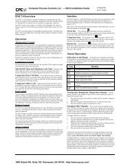
How to Use This Guide<br />
Read this Guide completely as you install and start up your new AK-SC 255 controller.<br />
Scope of document<br />
The intended scope of the ‘On-Site Installation Guide’ is to provide guidance on how to mount, power and apply initial system<br />
settings. The goal of this guide is to ready the AK-SC255 for the commissioning phase, where more detailed documentation is<br />
available.<br />
Further recommended reading<br />
The following documentation is designed to provide further reading for commissioning and system setup, and is available via the<br />
following Danfoss web sites:<br />
http://www.danfos.us/foodretail<br />
http://www.danfoss.com/foodretail<br />
AK-SC255 REFERENCE MANUAL (RS.8D.M1.22)<br />
AK-SC255 ‘R’ SUPPLEMENT MANUAL (DKRCE.ES.R1)<br />
AK-SC255 ‘E’ SUPPLEMENT MANUAL (DKRCE.EC.R1)<br />
What’s Needed for Installation<br />
What you will need to finish the installation:<br />
1. A screwdriver<br />
2. A drill and fasteners appropriate to mounting the controller.<br />
3. A dedicated 120V a.c. or 230V a.c. circuit (the unit is fused internally at 1.0 Amp)<br />
4. OEM installations require a dedicated disconnect<br />
Wire and Cable Requirements<br />
AK-SC255 Power: ~100 to 240V a.c. 50/60Hz (Use approved local wiring codes of practice)<br />
AK-SC255D (DIN) 5 V d.c.<br />
Communications:<br />
Ethernet<br />
Approved Cat5 cable<br />
Host<br />
18-22AWG, Beldon or equivalent (or approved Cat5 if Ethernet is used as Host)<br />
I/O network<br />
18-22AWG, Beldon or equivalent (Twisted pair stranded wire with shield)<br />
A Note about Code Compliance<br />
Danfoss believes that no instruction in this guide violates any<br />
national or local electrical code, but the installer is responsible for<br />
compliance with any code applicable to the installation site. Use the<br />
installation drawing as reference.<br />
WARNING: To avoid risk of injury from electric shock, ensure correct<br />
electrical isolation is made before working within the enclosure.<br />
2<br />
WARNING - The AK-SC255 contains a 3 V battery (type CR2032) to maintain programmed settings. Do not<br />
recharge, disassemble or dispose of in fire. Danger of burn or explosion may occur if mistreated, follow local<br />
regulations for correct disposal. Replacement battery is available from typical battery stockists.
Table of Contents<br />
Mounting and Wiring 4-6<br />
Mounting 4<br />
Internal component layout 4/5<br />
Making connections to the controller 6<br />
Initial AK-SC255 configuration 7<br />
Approvals & Specifications 8-9<br />
AK-SC255 Network Protocols 10-11<br />
3
Mounting screw locations, general dimensions<br />
8.00”<br />
(203.2 mm)<br />
10.00”<br />
(254 mm)<br />
Serial Port<br />
Mounting and Wiring<br />
Mounting (AK-SC255 screen version)<br />
The mounting location should be flat, dry and free from major<br />
vibrations. The AK-SC255 should be mounted at eye level, with<br />
consideration for the following approximate outline dimensions:<br />
Unit Width 10.5” (266 mm)<br />
Unit Height 12.5” (317 mm)<br />
Unit Depth 2.5” (63 mm)<br />
Mounting holes 8.0” (203.2 mm) Width<br />
Mounting holes 10.00” (254 mm) Height<br />
3/4” (19 mm) Knockout<br />
To allow the door to fully open, ensure that there is an area at<br />
least 21” (533 mm) x 11” (280 mm) free, leaving room for conduit<br />
connections beneath the controller. Mount the controller<br />
using appropriate screws through the holes indicated at left,<br />
fastening the back of the controller enclosure securely to the<br />
flat surface chosen.<br />
Allow approx 3” (76 mm) for side access to local connection<br />
port (Danfoss cable part # 080Z0262)<br />
1” (25 mm) Knockout<br />
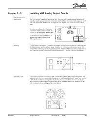
Internal Component layout (Base board)<br />
CR2032<br />
20.34” (516.34 mm)<br />
10.16” (258 mm)<br />
Internal component layout<br />
With the controller door open, the two main sections of the AK-<br />
SC255 can be seen, Base board & Connector board.<br />
Base board<br />
Mounted on the door frame is the ‘Base board’ with the main<br />
CPU card. The base board contains the following important<br />
components that need to be set for correct system operation:<br />
Battery (shipped in disabled position)<br />
Type CR2032 with (+) side facing toward the user.<br />
Engage battery circuit to ensure data is protected after<br />
power loss - set Jumper JP5 as follows. JP5<br />
Host RS485 / Modbus Network<br />
The AK-SC255 system utilizes a selectable RS485 / Mod<br />
bus port (located on Connector board). The unit<br />
comes factory set as Modbus communications.<br />
To enable RS485 Host network, Jumpers JP3 & JP4<br />
need to be set. Note that if Modbus is used, RS485<br />
host is not available - set host to Ethernet in AK-SC255<br />
software.<br />
CPU Card<br />
JP3<br />
JP4<br />
JP3 & JP4 not connected = RS485 Host<br />
JP3 & JP4 connected = EKC Modbus<br />
System address switch<br />
Rotary address switch to set AK-SC255 address<br />
Address 0 = Master (1-9 for Slave units)<br />
4<br />
System Reset<br />
Use the CPU reset button to reset the AK-SC255
Connector Board - User Connections<br />
Internal component layout cont.<br />
Connector board<br />
The Connector board contains the main user connection ports<br />
needed for communications, relay output and power supply:<br />
Ethernet<br />
Standard RJ45 Ethernet port, used for TCP/IP<br />
remote connection (LAN,WAN), SNMP network<br />
support & Host network. Use Ethernet as Host network<br />
if ‘Virtual Display’ functionality is required.<br />
Ethernet<br />
External<br />
Modem<br />
Port<br />
Output<br />
relay<br />
RS485<br />
/Modbus<br />
Lonworks® Communication<br />
Power<br />
Supply<br />
RS485 Host network / Modbus<br />
Use the RS485 port either for RS485 Host or EKC Mod<br />
bus communications. For RS485 Host communica<br />
tions, use 2 conductor shield cable. Up to 10 AK-SC<br />
255 controllers can be connected in a host network.<br />
Host / Modbus network options JP3 & JP4 Notes<br />
RS485 Host OFF Used when combining AKC55 / 255 on host<br />
120 Ohm terminator to be on 1st & last unit<br />
EKC Modbus<br />
ON<br />
(factory set)<br />
Use for EKC Modbus controllers<br />
120 Ohm terminator to be on last controller only<br />
If host network required use Ethernet<br />
Ethernet Host N/A Use Ethernet port and connect to LAN<br />
Configure in ‘Communications’ section<br />
Lonworks® I/O Network (TP78, RS485, FTT10 options available)<br />
Depending on protocol type, the number of network ports will differ<br />
External Modem<br />
Modem port used in conjunction with Modem<br />
Adapter kit 080Z2100<br />
Relay<br />
Rated at 30V d.c. 1Amp. Used for external alarm<br />
signal.<br />
AK-I/O Modules..<br />
AK-I/O Modules<br />
Terminator<br />
Terminator<br />
Generic Controller devices<br />
AK & EKC controllers<br />
Lonworks® I/O Network<br />
The I/O (Input-Output) network uses Echelon® Lon<br />
Talk® communications. Depending on AK-SC255<br />
version, up to five I/O network cables can be<br />
connected to each AK-SC 255. When<br />
connecting “A” and “B” conductors, there is no polarity<br />
to observe for AK I/O modules. For more information<br />
about connecting I/O cables, and restrictions on their<br />
length and layout, consult the AK-SC255 Reference<br />
Manual. Attach a terminator to each set of unused I/O<br />
terminals.<br />
For Generic networks (EKC & AK controllers) it is<br />
recommended only to use one of the five ports available.<br />
Follow network wiring regulations for each of<br />
the different network types. For additional in<br />
formation on networks consult Danfoss document<br />
entitled ‘Data communication between ADAP-KOOL®<br />
Refrigeration Controls’ (RC8AC302)<br />
5
L<br />
N G<br />
Making connections to the controller<br />
Conduit entrances are located both on the bottom of the controller<br />
and at the back. Five, 7/8” (22 mm) conduit access ports<br />
are available at the bottom. Located at the rear, there are three<br />
1 1/8” (28 mm) ports with an additional 7/8” (22 mm) port.<br />
Make sure any I/O network and communication runs are kept<br />
separate from the mains power.<br />
G<br />
N<br />
L<br />
Power Supply<br />
~100 to 240 V a.c.<br />
50/60 Hz<br />
Direct connect (side port) using Danfoss cable 080Z0262<br />
Power connection<br />
The AK-SC255 has an auto sensing power supply and is intended<br />
for voltage ranges 100 - 240 V a.c. 50/60 Hz. An onboard<br />
fuse rated at 1 Amp protects the internal electronics. Ensure<br />
the same type / rating fuse is used if required.<br />
The AK-SC255D (DIN) mount should be powered with a 5 V d.c.<br />
supply.<br />
AKA 65<br />
Software<br />
Local connection<br />
A local connection to a PC can be established using either<br />
Ethernet or via the RS232 direct connect port (located at the<br />
right hand side of the AK-SC 255 or the RS232 port on the DIN<br />
AK-SC255 model). For local connection via RS232 use Danfoss<br />
cable part # 080Z0262.<br />
AK-SC255D (DIN Mount version)<br />
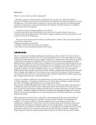
External connection by dial-up modem<br />
When using a modem to connect / dial out alarms, it is recommended<br />
that the modem adapter kit (080Z2100) is used.<br />
From the Main Menu select ‘Communications’. Goto ‘Modem<br />
Config’. Answer the system question ‘yes’ to ‘Configure modem<br />
on this unit:’ Next, use the drop down list (see screen shot opposite)<br />
to select your modem type.<br />
Ensure all other parameters are set (Baud rate, line type, Data &<br />
stop bit and parity). Typically these values can be left as ‘factory<br />
standard’.<br />
The final setting, ‘Disconnect method’ refers to the way the<br />
modem is disconnected after use. Use the ‘Power down’ option<br />
if a modem adapter is being used. This will toggle the adapter<br />
and ensure a clean power re-set.<br />
6<br />
Modem Config page (choose modem type)
Initial AK-SC255 configuration<br />
To get the AK-SC255 ready for full commissioning, a few steps should be implemented. The following section covers the typical<br />
settings required for commissioning preparation.<br />
Main Menu - Icon Overview<br />
Factory authorization code:<br />
12345 (enter)<br />
50 (enter)<br />
Authorization Menu<br />
Authorization<br />
After a successful boot up the AK-SC 255 will display the ‘Main Menu’. Move the cursor, using the arrow keys, to the menu item<br />
“Authorization” and press the ENTER KEY.<br />
On the Authorization screen, the cursor is on a field called “Auth.” Below that is a field called “Account.” Your first operation, each<br />
time you use the controller, will be to enter your authorization code and account number. These will be given to you by the system<br />
owner. The default authorization code from the Danfoss factory is 12345, and the default account code is 50. Once the correct<br />
supervisor code has been entered the screen will change and reflect ‘supervisor’ (assuming the factory code is valid and has not<br />
been replaced).<br />
Store Info<br />
The ‘Store Info’ icon contains various settings that reflect language, preferences, opening hours and other configuration parameters.<br />
See the following page for an overview of the main areas - configure as required.<br />
7
Opening Hours<br />
Used in conjunction with relative lighting<br />
Schedules (00:00 - 00:00 = always on)<br />
Store Name: provide name<br />
Store Clock / Time<br />
Sync clocks at midnight: Set to ‘yes’ if master AK-SC255 is to<br />
send time to slave AK-SC255 units (on host network)<br />
Time Zone: Used to correctly ‘time stamp’ e-mail alarms<br />
Unit /Language<br />
Set appropriate units & language<br />
Holidays<br />
Configure as required<br />
(up to 8 holidays)<br />
Used in conjunction with schedules<br />
Contact Info<br />
Configure as required<br />
Manager Override<br />
Configure as required<br />
Daylight Savings<br />
Configure to automatically<br />
change AK-SC255 system clock<br />
Preferences<br />
Set as per user requirements<br />
Leak Detector<br />
Configure as required<br />
Approvals & Specifications<br />
10 ¼” (262 mm) 2 ½ “(63 mm)<br />
6” (153 mm)<br />
5” (127 mm)<br />
12½” (317 mm)<br />
8<br />
AK-SC255D<br />
DIN Mounted System Manager<br />
AK-SC255<br />
System Manager
Approvals & Specifications<br />
Address Switch<br />
Battery Jumper<br />
circuit<br />
Battery<br />
Direct<br />
Connect<br />
Port<br />
User Label<br />
Door latch<br />
Fuse (1 Amp)<br />
30 V d.c.<br />
CPU Board<br />
Base Board<br />
Ethernet<br />
External Modem<br />
Port<br />
LonWorks© Port(s) Power Connection<br />
(100 - 240 V a.c.)<br />
RS485 / Modbus<br />
Alarm Relay<br />
* not available on RS485 & FTT10 models<br />
RS485 / Modbus<br />
Address Switch<br />
Ethernet<br />
Direct Connect<br />
Power Connection<br />
(5 V d.c.)<br />
External Modem<br />
Port<br />
Environmental Range AK-SC255 & AK-Sc255D (DIN)<br />
Operating temperature<br />
32 to 104˚F (0 to +40˚c)<br />
32 to 122 ˚F (0 to +50˚c AK-SC255D)<br />
@ 90% RH (non condensing)<br />
LonWorks© Port(s)<br />
Alarm Relay<br />
* not available on RS485 & FTT10 models<br />
Electrical range<br />
~ 100 - 240 V a.c. (+ / - 10%) 5 V d.c. (AK-SC255D)<br />
50 - 60 Hz<br />
UL File # E166834<br />
9
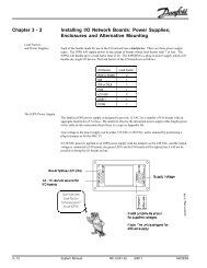
AK-SC255 Available network protocols - Topology Examples<br />
AK-SC255 TP78 version<br />
This example shows the AK-SC255 TP 78 version (screen model). The TP 78 screen<br />
version has 5 network ports, whereas the AK-SC255 DIN version has 3 TP 78 network<br />
ports. The TP 78 network protocol must be wired in a ‘daisy chain’ format and is not<br />
polarity sensitive.<br />
AK-SC255 TP78 version<br />
(5 network ports available - screen<br />
3 network ports available - DIN)<br />
Terminator (120 Ohm)<br />
TP78<br />
AK I/O<br />
Comm<br />
TP78<br />
AK I/O<br />
Comm<br />
AK I/O<br />
Module<br />
AK I/O<br />
Module<br />
AK I/O<br />
Module<br />
AK I/O<br />
Module<br />
AK-SC255 RS485 version<br />
This example shows the AK-SC255 RS485 version. Both screen and DIN models have<br />
a single RS485 communication port. The RS485 network protocol must be wired in a<br />
‘daisy chain’ format - recommended that polarity is maintained.<br />
AK-SC255<br />
Terminator<br />
(120 Ohm)<br />
AK-SC255 RS485 version<br />
(1 network port available)<br />
RS485<br />
Controller<br />
Controller Controller Controller Controller<br />
Controller Controller Controller Controller Last Device<br />
Terminator<br />
(120 Ohm)<br />
AK-SC255 RS485 version (mid network connection)<br />
A B Shield<br />
This example shows the AK-SC255 RS485 version used<br />
in the middle of a network run. In this example<br />
ensure that both ends of the controller run are fitted<br />
with 120 Ohm terminators.<br />
Terminator<br />
(120 Ohm)<br />
RS485<br />
Terminator<br />
(120 Ohm)<br />
Controller Controller Controller<br />
Controller Controller Controller<br />
10
AK-SC255 FTT10 version<br />
This example shows the AK-SC255 FTT10 version. The FTT10 network protocol can be<br />
wired in a ‘Star’ format, with a 51 Ohm resister located at the 'star' point.<br />
Controller<br />
Controller Controller Controller<br />
AK-SC255 FTT10 version<br />
(5 network ports available)<br />
Terminator at Star<br />
(51 Ohm)<br />
Controller<br />
Controller Controller Controller<br />
Controller<br />
Controller Controller Controller<br />
Notes:<br />
11
ADAP-KOOL® Refrigeration Control Systems is a trademark of Danfoss A/S, www.danfoss.com<br />
Danfoss Inc., Refrigeration & Air-Conditioning Division, 7941 Corporate Drive, Baltimore, MD 21236 Tel. 410-931-8250, Fax 410-931-8256,<br />
www.danfoss.com/North_America<br />
Danfoss can accept no responsibility for possible errors in catalogs, brochures, or other printed material. Danfoss reserves the right to alter its products without notice. This also applies to products already on order provided that alterations can be made without<br />
subsequential changes being necessary in specifications already agreed. All trademarks in this material are property of the respective companies. Danfoss and the Danfoss logotype are trademarks of Danfoss A/S. All rights reserved.<br />
12<br />
AK-SC255 Installation Guide <strong>USCO</strong>.<strong>PI</strong>.<strong>R1.A3</strong>.22/ 521U0086 ©Danfoss 02-2008