MR4PMUHV Electronic Temperature/Defrost Control ... - icemeister.net
MR4PMUHV Electronic Temperature/Defrost Control ... - icemeister.net
MR4PMUHV Electronic Temperature/Defrost Control ... - icemeister.net

You also want an ePaper? Increase the reach of your titles
YUMPU automatically turns print PDFs into web optimized ePapers that Google loves.
Master Catalog 125<br />
<strong>Temperature</strong> <strong>Control</strong>s Section A<br />
Product/Technical Bulletin<br />
Issue Date 1098<br />
<strong>MR4PMUHV</strong> <strong>Electronic</strong><br />
<strong>Temperature</strong>/<strong>Defrost</strong> <strong>Control</strong> with Relay Pack<br />
The MR series temperature controls are designed for<br />
hot gas or electric heat defrost in both refrigeration and<br />
freezer units. Either time or temperature based defrost<br />
termination may be selected.<br />
The MR series incorporates control functions<br />
such as compressor control, defrost management,<br />
fan management, and alarm management.<br />
One convenient package consolidates the functions of<br />
a thermostat, a digital temperature readout device,<br />
a timer, and a defrost termination switch. This<br />
microprocessor based control offers innovative<br />
features and state-of-the-art technology.<br />
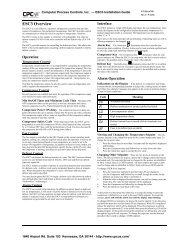
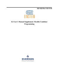
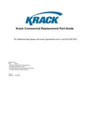
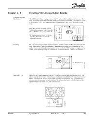
Figure 1: <strong>MR4PMUHV</strong>-12 <strong>Electronic</strong><br />
<strong>Temperature</strong>/<strong>Defrost</strong> <strong>Control</strong> with Relay Pack<br />
Features and Benefits<br />
❑ Single Package<br />
❑ Mounting Flexibility<br />
❑ Easily Readable <strong>Temperature</strong><br />
Display<br />
❑ Accurate, Interchangeable<br />
<strong>Temperature</strong> Sensor<br />
❑ Heavy Duty Relays<br />
❑ Alarm Management<br />
Functions<br />
Provides the functionality of multiple components<br />
at a cost effective price<br />
Allows control and relay pack to be mounted<br />
together or separately, facilitating multiple<br />
configurations<br />
Displays both evaporator and process<br />
temperature quickly; helps troubleshoot system<br />
Provides accurate control performance with up to<br />
300 feet of wiring (An offset is provided for longer<br />
wiring.)<br />
Allows direct control of compressors, fans<br />
heaters, and alarms; reduces installation time<br />
Provides both local alarm codes and a relay<br />
closure that can be used to trigger a remote<br />
alarm or a dial-out modem<br />
© 1998 Johnson <strong>Control</strong>s, Inc. 1<br />
Part No. 24-8790-18, Rev. C<br />
www.johnsoncontrols.com<br />
Code No. LIT-125190
O verview<br />
!<br />
WARNING: All <strong>MR4PMUHV</strong> controls are<br />
designed for use only as<br />
operating controls. Where an<br />
operating control failure would<br />
result in personal injury or loss<br />
of property, it is the<br />
responsibility of the installer to<br />
add devices (safety, limit<br />
controls) or systems (alarm,<br />
supervisory systems) that<br />
protect against, or warn of,<br />
control failure.<br />
These relay pack mounted controls provide direct<br />
control of compressors up to 2 hp, electric heater<br />
loads of up to 20 amperes, and evaporator fan loads<br />
of up to 3/4 hp. The need for separate relays is<br />
eliminated in these applications. In addition, the<br />
<strong>MR4PMUHV</strong> controls combine the functionality of an<br />
electromechanical thermostat, mechanical clock,<br />
defrost termination device, and temperature readout<br />
device with the accuracy of electronic technology.<br />
Compressor <strong>Control</strong> Functions<br />
Compressor <strong>Control</strong>: All <strong>MR4PMUHV</strong> controls<br />
feature temperature based, On/Off control of a<br />
compressor.<br />
Anti-Short Cycle Delay: To avoid situations where<br />
the compressor starts, stops, and restarts in a short<br />
period of time, all models have a built-in anti-short<br />
cycle delay. This feature determines the minimum<br />
time between two subsequent On cycles of the<br />
compressor.<br />
Deep Freeze Cycle<br />
From the front panel, the compressor output can be<br />
forced On for a preset time to manually initiate a<br />
freeze cycle. This feature is handy when loading a<br />
cold room or a display cabi<strong>net</strong>.<br />
<strong>Defrost</strong> Functions<br />
<strong>Defrost</strong> Termination may be based on evaporator<br />
temperature or time.<br />
<strong>Defrost</strong> Mode: The <strong>MR4PMUHV</strong> control can perform<br />
either hot gas or electrical defrost. During a hot gas<br />
defrost cycle, both the compressor and defrost<br />
terminals are energized. Hot gas is produced and<br />
delivered to the evaporator coil via a solenoid valve<br />
controlled by the defrost relay. During an electrical<br />
defrost cycle, the compressor terminals are<br />
de-energized and defrost terminals are energized to<br />
turn on the electric defrost heater.<br />
Manual <strong>Defrost</strong>: Initiating the manual defrost<br />
sequence interrupts the current control state and<br />
begins an immediate defrost cycle.<br />
Fan <strong>Control</strong> Functions<br />
The <strong>MR4PMUHV</strong> control can manage an evaporator<br />
fan in one of two ways. The fan can either run<br />
continuously or run only when the compressor is on,<br />
and can be set to follow either time or evaporator<br />
temperature based startup after defrost. Because the<br />
<strong>MR4PMUHV</strong> control uses an SPDT relay for fan<br />
control, a reversible fan motor can also be wired to<br />
run in reverse to bring warm air over the evaporator<br />
coils in a timed defrost application.<br />
Alarm Management Functions<br />
High and Low <strong>Temperature</strong> Alarm: The high and<br />
low temperature alarms are set relative to the<br />
setpoint. If the temperature exceeds the alarm values,<br />
an alarm output relay is energized, and the display<br />
flashes either +L or /R. High and low temperature<br />
alarms are disabled during defrost and for 20 minutes<br />
after the defrost cycle. Alarms are also disabled for<br />
20 minutes after startup.<br />
Alarm Time Delay: A time delay can be configured in<br />
order to keep short-duration events from triggering<br />
the alarm (i.e., door open).<br />
Alarm Differential: An alarm differential can be set to<br />
keep the alarm from cycling rapidly on and off.<br />
Selectable Sensor Failure Mode: <strong>Temperature</strong><br />
sensor failure is indicated by an alarm. The controller<br />
can be programmed for one of three sensor failure<br />
modes: (1) the system shuts down, (2) the system<br />
runs constantly, (3) the controller automatically starts<br />
and stops the compressor based on the average<br />
running times of the last four cycles.<br />
2 A—<strong>MR4PMUHV</strong> <strong>Electronic</strong> <strong>Temperature</strong>/<strong>Defrost</strong> <strong>Control</strong> with Relay Pack Product/Technical Bulletin
Additional Features<br />
Sensor Input: This series of controllers uses the<br />
Johnson <strong>Control</strong>s A99 temperature sensor. The<br />
controller allows you to program an offset of the<br />
measured temperature for temperature<br />
compensation or cable extension longer than 300 ft.<br />
Adjustable Setpoint Stops: The setpoint stops<br />
restrict the amount of change that the end user can<br />
make to the setpoint. The end user cannot set a<br />
setpoint value exceeding these limits.<br />
Keyboard Locking: A sequence of key strokes<br />
allows you to disable/enable modification of the<br />
setpoint and other parameters. This prevents<br />
accidental or unauthorized parameter modifications.<br />
Self-test Procedure: This feature helps check<br />
controller operation. After a key stroke sequence,<br />
the control will cycle all outputs and test all LEDs.<br />
Display Updating Time: The display update setting<br />
provides an adjustable refresh rate for the<br />
temperature readout. This feature is useful to avoid<br />
displaying minor intermittent changes of<br />
temperature.<br />
Units of Measurement: <strong>Temperature</strong> units can be<br />
selected as either degrees Fahrenheit or degrees<br />
Celsius.<br />
FCC Compliance<br />
This equipment has been tested and found to comply<br />
with the limits for a Class A digital device pursuant to<br />
Part 15 of the FCC Rules. These limits are designed<br />
to provide reasonable protection against harmful<br />
interference when the equipment is operated in a<br />
commercial environment. This equipment generates,<br />
uses, and can radiate radio frequency energy and, if<br />
not installed and used in accordance with the<br />
instruction manual, may cause harmful interference to<br />
radio communications. Operation of this equipment in<br />
a residential area is likely to cause harmful<br />
interference, in which case the user will be required to<br />
correct the interference at his/her own expense.<br />
Canadian Compliance<br />
This digital apparatus does not exceed the Class A<br />
limits for radio noise emissions from digital apparatus<br />
set out in the Radio Interference Regulations of the<br />
Canadian Department of Communications.<br />
D imensions<br />
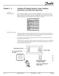
Display<br />
The display has 2 LED digits and a minus (-)<br />
indication. It displays a temperature range from<br />
-40 to 99°F (-40 to 70°C) in increments of 1F° or C°.<br />
Manual<br />
<strong>Defrost</strong><br />
Button<br />
Enter<br />
Button<br />
Fan<br />
Status<br />
LED<br />
<strong>Defrost</strong><br />
Status<br />
LED<br />
Compressor<br />
Status<br />
LED<br />
Up<br />
Button<br />
Down<br />
Button<br />
Figure 2: Front Panel and Display<br />
During normal operation, the display shows the<br />
process temperature. By pressing the Up or Down<br />
buttons, you can view the temperature, evaporator<br />
sensor temperature and the digital input status. By<br />
pressing the Enter button, you can also view the<br />
setpoint. After 15 seconds of inactivity, the display<br />
will return to the process temperature display.<br />
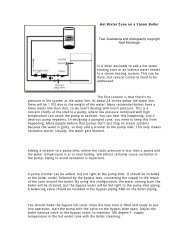
Figure 3: Relay Pack Dimensions, in. (mm)<br />
Figure 4: A99B-9108 Sensor, in. (mm)<br />
A—<strong>MR4PMUHV</strong> <strong>Electronic</strong> <strong>Temperature</strong>/<strong>Defrost</strong> <strong>Control</strong> with Relay Pack Product/Technical Bulletin 3
Separating the <strong>Control</strong> and Relay Pack<br />
The control may be mounted separately from the<br />
relay pack if desired. Follow the steps below to<br />
separate the control and the relay pack.<br />
1. Locate the mounting clip that holds the control to<br />
the relay pack, as shown below.<br />
4. When needed, disconnect and reconnect<br />
Terminals V1, V2, O1, and O2 in the relay pack<br />
to the corresponding terminals on the control.<br />
2. Squeeze the forward portion of the mounting clip<br />
together and slide the mounting clip back, as<br />
shown below.<br />
Loosen screw to open terminal;<br />
tighten screw to secure wiring.<br />
V1 V2 O1 O2<br />
3. Pull the control out of the mounting bracket on<br />
the relay pack, as shown below.<br />
Insert wiring here.<br />
4 A—<strong>MR4PMUHV</strong> <strong>Electronic</strong> <strong>Temperature</strong>/<strong>Defrost</strong> <strong>Control</strong> with Relay Pack Product/Technical Bulletin
W iring the A99 Sensors and Digital Input<br />
Wire the sensors and digital input (if used), as<br />
illustrated below. When wiring is complete, re-mount<br />
the control to the relay pack if desired.<br />
Relay Pack Terminal Block<br />
Figure 6: Relay Pack Terminal Block<br />
Figure 5: Wiring the A99 Sensor to <strong>MR4PMUHV</strong><br />
W iring the Relay Pack <strong>Control</strong><br />
!<br />
WARNING: Shock Hazard. To avoid<br />
possible electrical shock or<br />
damage to equipment,<br />
disconnect power supply<br />
before wiring any connections.<br />
Follow these wiring guidelines:<br />
• All wiring must conform to the National Electric<br />
Code and local regulations.<br />
• Make all wiring connections using adequate<br />
gauge copper conductors only.<br />
• Recommended wire gauge is 14 AWG for motor<br />
loads up to 12 FLA and non-inductive loads up to<br />
15 A.<br />
• Recommended wire gauge is 12 AWG with an<br />
insulation rating of 75°F for motor loads up to<br />
16 FLA and non-inductive loads up to 20 A.<br />
• Maximum recommended length is 50 feet.<br />
L1<br />
Internal to <strong>Control</strong><br />
L2<br />
240 120 ALM FNO L2 FNC CP1 CP2 DH1 DH2<br />
Alarm<br />
Evaporator Fan<br />
*This wiring should only be<br />
used with reversible fan<br />
motors to reverse airflow<br />
during defrost.<br />
Compressor<br />
<strong>Defrost</strong><br />
Heater<br />
Figure 7: Typical 240 VAC Relay Pack Wiring Connections<br />
A—<strong>MR4PMUHV</strong> <strong>Electronic</strong> <strong>Temperature</strong>/<strong>Defrost</strong> <strong>Control</strong> with Relay Pack Product/Technical Bulletin 5
Figure 8: Typical 120 VAC Relay Pack Wiring Connections<br />
Alarm and Fault Codes<br />
These alarm and fault codes will flash on the display when the control detects the following faults:<br />
Table 1: Error Codes and Status<br />
Error Code<br />
System Status<br />
)<br />
Indicates an open or shorted temperature sensor<br />
)<br />
Indicates an open or shorted evaporator sensor<br />
$<br />
Indicates that the digital input was open for longer than the time<br />
delay (LG) and digital input (L)) Option 1 is selected<br />
$<br />
Digital input closed for longer than time delay (LG)<br />
and digital input (L)) Option 2 is selected<br />
$<br />
Digital input open for longer than the time delay (LG)<br />
and digital input (L)) Option 3 selected<br />
+,<br />
<strong>Temperature</strong> has exceeded the high temperature alarm value ($+)<br />
/2<br />
<strong>Temperature</strong> has fallen below the low temperature alarm value ($/)<br />
((<br />
Program failure<br />
Alarm output is on. Compressor runs according to the sensor<br />
failure mode selected (parameter 6)).<br />
Cycle power to reset control.<br />
Alarm output is on. <strong>Defrost</strong> cycle is controlled by parameters<br />
GL (defrost initiation) and GG (defrost duration). Correct<br />
problem to reset control.<br />
Compressor output is off. Alarm output is on. Correct problem<br />
to reset control.<br />
Alarm output is on. Correct problem to reset control.<br />
Fan output is off. Alarm output is on. Correct problem to reset<br />
control.<br />
Alarm output is on. Correct problem to reset control.<br />
Alarm output is on. Correct problem to reset control.<br />
Alarm output is on. Other outputs are off. Replace control.<br />
6 A—<strong>MR4PMUHV</strong> <strong>Electronic</strong> <strong>Temperature</strong>/<strong>Defrost</strong> <strong>Control</strong> with Relay Pack Product/Technical Bulletin
Programming the <strong>Control</strong><br />
To lock and unlock the unit for<br />
programming<br />
To change the setpoint<br />
Note:<br />
Press the Enter, Up, and<br />
Down buttons in sequence<br />
and hold them all down until<br />
“- - -” is displayed. Hold for<br />
about 10 seconds until the<br />
current temperature is<br />
displayed. This toggles the<br />
keypad between locked and<br />
unlocked.<br />
1. Hold the Enter button down<br />
for 3 seconds. The display will<br />
change to show the setpoint.<br />
Release the Enter button.<br />
2. Press the Up or Down button<br />
until you reach the new<br />
setpoint.<br />
3. Press the Enter button to<br />
save the new setpoint.<br />
If the Enter button is not pressed after<br />
selecting the new setpoint, the new setpoint<br />
is not saved, and the control will revert to the<br />
original setpoint.<br />
To begin a Manual <strong>Defrost</strong> Cycle<br />
Hold the <strong>Defrost</strong> button down for<br />
3 seconds.<br />
To program values other than the setpoint<br />
A parameter settings reference page is included in<br />
Table 3 of this bulletin. Filling out the parameter<br />
settings before programming may be helpful.<br />
Note:<br />
1. Hold the Enter button<br />
down for about<br />
10 seconds. The display<br />
will change to +
Parameter Definitions<br />
Setpoint: This is defined as the relay cut-off.<br />
The following parameters are described in the order<br />
that they are displayed on the control.<br />
+< Hysteresis (Differential): This is the difference<br />
between the temperature at which the<br />
compressor output is switched Off and the<br />
temperature at which the output is switched On.<br />
This is an absolute value relative to the setpoint.<br />
Example:<br />
Setpoint = 34°F (4°C)<br />
Hysteresis = 2 degrees.<br />
The compressor is switched On when the<br />
temperature rises to 36°F (6°C), and is turned<br />
Off when the temperature falls to 34°F (4°C).<br />
// and +/ Low and high setpoint stop: The<br />
setpoint value cannot be adjusted outside the<br />
range defined by these parameters to avoid<br />
improper setpoint setting by the user.<br />
&& Anti-short cycle delay: This parameter prevents<br />
the compressor from being turned On, Off, and<br />
back On too quickly. The value set is the<br />
minimum time between two subsequent On<br />
cycles of the output.<br />
Anti-Short Cycle<br />
Timer<br />
Load Demand<br />
Output Status<br />
&R Deep freezing time: This is the amount of time<br />
that the compressor is forced On when the deep<br />
freezing cycle is initiated.<br />
$+ High temperature alarm: High temperature<br />
alarm value relative to setpoint.<br />
Example:<br />
If the set point is at 34°F and the alarm value is<br />
set to 5 degrees, the alarm is activated at 39°F.<br />
$/ Low temperature alarm: Low temperature alarm<br />
value relative to setpoint.<br />
Example:<br />
If the set point is 34°F and the alarm value is set<br />
at -3 degrees, the alarm is activated at 31°F.<br />
$G Alarm differential: Avoids alarm oscillation.<br />
Example:<br />
Setpoint = 34°F,<br />
High temperature alarm = 6 degrees,<br />
Alarm differential = 2 degrees.<br />
When the temperature exceeds<br />
34°F + 6F° = 40°F for a time greater than<br />
parameter $W, the alarm is activated; when<br />
temperature drops below 34°F + 6F°-2F° = 38°F,<br />
the alarm is deactivated.<br />
$W Alarm time delay: Delay between the detection<br />
of a temperature alarm and the activation of the<br />
alarm. This allows the control to ignore shortterm<br />
or transient alarm conditions during the<br />
time delay. The controller also ignores<br />
temperature alarms in the following cases:<br />
• for 20 minutes after power On<br />
• during defrost and for 20 minutes after the<br />
defrost end<br />
G) <strong>Defrost</strong> type: Selects the type of installation and<br />
the way defrost is performed:<br />
0 = Electrical defrost<br />
(compressor off during defrost)<br />
1 = Hot gas defrost<br />
(compressor on during defrost)<br />
G( <strong>Defrost</strong> end mode: Selects the defrost<br />
termination type:<br />
0 = Timer based; set with parameter GG<br />
Note: Evaporator fan operation will restart<br />
based on time<br />
1 = <strong>Temperature</strong> based; set with parameter GW<br />
Note: The defrost cycle always ends after<br />
the time set for parameter GG<br />
elapses.<br />
GW <strong>Defrost</strong> termination temperature: Used only<br />
when parameter G(=1. When the evaporator<br />
temperature reaches this value, the defrost<br />
automatically ends.<br />
GL <strong>Defrost</strong> interval: This is the time between<br />
two subsequent defrost cycles.<br />
Note: When the defrost interval (GL) is 1 hour,<br />
the maximum defrost duration (GG)<br />
cannot be set at more than 40 minutes.<br />
GG Maximum defrost duration: The defrost cycle<br />
will stop after this time, even if the defrost end<br />
temperature has not been reached. Setting GG to<br />
8 A—<strong>MR4PMUHV</strong> <strong>Electronic</strong> <strong>Temperature</strong>/<strong>Defrost</strong> <strong>Control</strong> with Relay Pack Product/Technical Bulletin
0 disables the defrost cycle in both manual and<br />
automatic modes.<br />
G& Dripping time: After defrost is terminated, the<br />
compressor is stopped for this length of time to<br />
allow the evaporator to drip.<br />
G8 First defrost after power-on: This parameter<br />
delays the first defrost cycle after powerup. The<br />
control will not initiate a defrost cycle for the<br />
length of time set in this parameter. It can be<br />
used to allow the system to reach operating<br />
temperature before the defrost cycle is initiated.<br />
Setting this parameter to 2) (Off) disables the<br />
first defrost after power-on. Normally, the first<br />
defrost occurs after the GL interval has elapsed.<br />
G3 Display during defrost: Selects what<br />
temperature is displayed during a defrost cycle:<br />
0 = Last measured value before defrost cycle<br />
1 = Setpoint<br />
GU Display delay after defrost: During defrost<br />
cycles, the ambient temperature is not displayed<br />
(see parameter G3). The actual temperature is<br />
displayed when it reaches the setpoint value or<br />
after the time defined by this parameter.<br />
L) Digital input function: The digital input (normally<br />
closed) can be configured according to<br />
installation requirements:<br />
0 = The digital input is not connected<br />
1 = If the contact is open for a time longer than<br />
that set through parameter LG, the<br />
compressor, defrost, and fan outputs are<br />
switched Off, an alarm message (A1) is<br />
displayed, and the alarm output is switched<br />
On.<br />
2 = Alarm function: If the contact is open for a<br />
time longer than that set through parameter<br />
LG, an alarm message (A2) is displayed and<br />
the alarm output is switched On.<br />
3 = Open door alarm: When the contact is open,<br />
the fan is switched Off. If the contact is open<br />
for longer than the time set through<br />
parameter LG, an alarm message (A3) is<br />
displayed, the alarm output is switched On,<br />
and high and low temperature alarms are<br />
disabled.<br />
LG Digital input time delay: This is the time<br />
between the detection of the digital input<br />
opening and the enabling of the function<br />
selected through parameter L).<br />
)) Fan operating function:<br />
0 = Fan runs when the compressor runs<br />
1 = Fan is always On<br />
Note: The fan is always switched Off during<br />
the defrost cycle.<br />
)G Fan start-up delay (after defrost): The fan is<br />
activated after this time even if the temperature<br />
set through parameter )U has not been reached.<br />
)U Fan start temperature after defrost end: This is<br />
the evaporator sensor temperature at which the<br />
fan is switched On after a defrost cycle.<br />
Note: If the start temperature is not reached,<br />
the fan is switched On after the time set<br />
in parameter )G.<br />
6) Sensor failure operation: This parameter<br />
defines how the control functions after a<br />
temperature sensor failure:<br />
0 = Compressor remains On<br />
1 = Compressor remains Off<br />
2 = Automatic:<br />
In automatic mode, the controller calculates the<br />
average time the compressor was On during the<br />
last four cycles. The controller then cycles based<br />
on the average of these cycles. If a deep freezing<br />
cycle or a defrost cycle occurred in the last four<br />
cycles, they will not be taken into account nor will<br />
the first cycle after the deep freeze or defrost.<br />
6R <strong>Temperature</strong> sensor offset: This value is added<br />
to or subtracted from the measured value to<br />
compensate for possible field measurement<br />
offset errors. To compensate for extra long<br />
copper cabling use the following table:<br />
Table 2: Wire Size and Cable Length<br />
Wire Size and Cable Length<br />
18 AWG 20 AWG 22AWG<br />
Offset<br />
300-599 ft 190-374 ft 120-239 ft 1F°<br />
600-899 ft 375-564 ft 240-349 ft 2F°<br />
900+ ft 565+ ft 350+ ft 3F°<br />
8Q <strong>Temperature</strong> units used: Determines<br />
temperature units used for parameter settings.<br />
0 = Celsius degrees<br />
1 = Fahrenheit degrees<br />
38 Display refresh rate: The temperature display is<br />
refreshed at this rate. The display refresh rate<br />
does not affect control performance.<br />
A—<strong>MR4PMUHV</strong> <strong>Electronic</strong> <strong>Temperature</strong>/<strong>Defrost</strong> <strong>Control</strong> with Relay Pack Product/Technical Bulletin 9
Parameter Settings<br />
Table 3: Parameter Settings<br />
Parameter Range Factory<br />
Setting<br />
Setpoint<br />
-67 to 99°F (-55 to 99°C)<br />
+
O rdering Information<br />
Table 4: Order Information<br />
Item Code Description Shipping weight<br />
<strong>MR4PMUHV</strong>-12C Relay pack defrost control with two A99 sensors 2.9 lb (1320g)<br />
MR4PM12C-12C Replacement control for use in relay pack only 1.6 lb (726g)<br />
RP4MRUHV-1C Relay pack without control 2.3 lb (1060g)<br />
A99B-9108 Sensor, cable length: 6.6 ft (2m) 0.13 lb (60g)<br />
Repair and Replacement<br />
Field repair of the control is not possible. In case of a<br />
defective or improperly functioning control, please<br />
check with your nearest Johnson <strong>Control</strong>s/PENN<br />
representative. When contacting the supplier for<br />
replacement, state the model number of the control.<br />
This number can be found on the data plate.<br />
Table 5: SPST Compressor Relay<br />
Electrical Ratings*<br />
Motor Ratings (VAC) 24 120 208 240<br />
Horsepower Rating 1 1.5 2<br />
AC Full Load Ampere 16 11 12<br />
AC Locked Rotor Ampere 96 66 72<br />
Pilot Duty (VA) 125 750 875 1125<br />
*Ambient Operation: As above for -40 to 44°C, derate<br />
electrical ratings 6.25% per 1C° between 45°C to 60°C.<br />
Table 6: SPDT Fan Relay Electrical<br />
Ratings*<br />
Motor Ratings (VAC) 24 120 208 240<br />
Horsepower Rating 1/3 1/2 3/4<br />
AC Full Load Ampere 7.2 5.65 6.9<br />
AC Locked Rotor Ampere 43.2 33.9 41.4<br />
Pilot Duty (VA) 50 325 450 600<br />
Table 7: SPST <strong>Defrost</strong> Heater Relay<br />
Electrical Ratings*<br />
Motor Ratings (VAC) 24 120 208 240<br />
Horsepower Rating 1 1.5 2<br />
AC Full Load Ampere 16 11 12<br />
AC Locked Rotor Ampere 96 66 72<br />
Non-Inductive Load<br />
Ampere<br />
20 20 20<br />
Pilot Duty (VA) 125 750 825 1125<br />
*Ambient Operation: As above for -40 to 44°C, derate<br />
electrical ratings 6.25% per 1C° between 45°C to 60°C.<br />
Table 8: SPST Alarm Relay Electrical<br />
Ratings*<br />
Motor Ratings (VAC) 24 120 208 240<br />
Non-Inductive Load<br />
Ampere<br />
5 5 5 5<br />
Pilot Duty (VA) 125 250 325<br />
*Ambient Operation: As above for -40 to 44°C, derate<br />
electrical ratings 6.25% per 1C° between 45°C to 60°C.<br />
Input Power: 5VA @240, 5VA @120<br />
Supply Level: 120 and L1: 120 VAC +10%/-15%<br />
240 and L1: 240 VAC +10%/-15%<br />
Operating Frequency: 60 Hz @ 120/240 VAC<br />
*Ambient Operation: As above for -40 to 44°C, derate<br />
electrical ratings 6.25% per 1C° between 45°C to 60°C.<br />
A—<strong>MR4PMUHV</strong> <strong>Electronic</strong> <strong>Temperature</strong>/<strong>Defrost</strong> <strong>Control</strong> with Relay Pack Product/Technical Bulletin 11
Specifications<br />
Product<br />
Electrical Ratings See Tables 5-9.<br />
Frequency<br />
<strong>MR4PMUHV</strong>-12C <strong>Defrost</strong> <strong>Control</strong><br />
60 Hz<br />
Power Consumption 5VA @240, 5VA @120<br />
Accuracy<br />
A99 Sensor Cable<br />
Ambient Operating<br />
Conditions<br />
Ambient Storage Conditions<br />
Dimensions (H x W x D)<br />
Agency Listings<br />
Shipping Weight<br />
± 1.8F° ( ± 1C°)<br />
6.6 ft (2m)<br />
<strong>MR4PMUHV</strong>-12C:<br />
MR4PM12C-12C:<br />
RP4MRUHV-1C:<br />
<strong>MR4PMUHV</strong>-12C:<br />
MR4PM12C-12C:<br />
RP4MRUHV-1C<br />
+14 to +111°F (-10 to +44°C); derate 6.25% per 1°C from 45°C to 60°C;<br />
0 to 95 % RH (non-condensing)<br />
+14 to +140°F (-10 to +60°C);<br />
0 to 95 % RH (non-condensing)<br />
-40 to +111°F ( -40 to +44°C); derate 6.25% per 1°C from 45°C to 60°C;<br />
0 to 95 % RH (non-condensing)<br />
-22 to +176°F (-30 to +80°C)<br />
0 to 95 % RH (non-condensing)<br />
-22 to +176°F (-30 to +80°C)<br />
0 to 95 % RH (non-condensing)<br />
-40 to +185°F (-40 to +85°C)<br />
0 to 95 % RH (non-condensing)<br />
7.94 x 3.6 x 2.4 in. (202 x 92 x 61 mm)<br />
UL Listed (File SA516, UL Guide SDFY; cUL Guide SDFY7)<br />
2.9 lb (1320g)<br />
The performance specifications are nominal and conform to acceptable industry standards. For application at conditions beyond these specifications,<br />
consult Johnson <strong>Control</strong>s/Penn Application Engineering at (414) 274-5535. Johnson <strong>Control</strong>s, Inc. shall not be liable for damages resulting from<br />
misapplication or misuse of its products.<br />
<strong>Control</strong>s Group<br />
www.johnsoncontrols.com<br />
507 E. Michigan Street FAN 125<br />
P.O. Box 423<br />
Master Catalog<br />
Milwaukee, WI 53201<br />
Printed in U.S.A.<br />
12 A—<strong>MR4PMUHV</strong> <strong>Electronic</strong> <strong>Temperature</strong>/<strong>Defrost</strong> <strong>Control</strong> with Relay Pack Product/Technical Bulletin