Parker A8 Valve.pdf - icemeister.net
Parker A8 Valve.pdf - icemeister.net
Parker A8 Valve.pdf - icemeister.net

Create successful ePaper yourself
Turn your PDF publications into a flip-book with our unique Google optimized e-Paper software.
COMPACT WIDE-RANGE<br />
PRESSURE REGULATORS<br />
Type <strong>A8</strong>A, <strong>A8</strong>1, <strong>A8</strong>2<br />
Ports 9mm (3/8”) to 66mm (2 5 /8”) Nom.<br />
FEATURES<br />
• Dual spring for wide range pressure set-points<br />
• Pilot operated for close control at desired set-point<br />
• Excellent regulation at light loads<br />
• Interchangeable capacity cartridges<br />
• Inlet, outlet or differential regulator functions<br />
• Low pressure drop<br />
• Few moving parts<br />
• Long-life stainless steel diaphragms (no bellows to fail)<br />
• Variations available for pilot electric shut-off and pilot electric wide-opening<br />
pressure control<br />
• Manual opening feature<br />
• All service from the top<br />
• Sweat-in-place without disassembly<br />
• Furnished with access fitting<br />
• UL listed (except 50 Hertz versions)<br />
SPECIFICATIONS<br />
• Design pressure (PS): 31.0 bar (450 psig)<br />
• Range: 250mm hg to 27.6 bar (10" hg to 400 psig)<br />
DESCRIPTION<br />
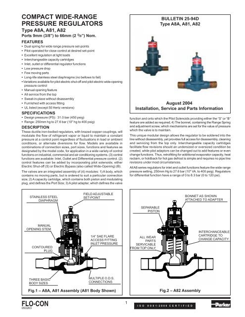
These ductile iron-bodied regulators, with brazed copper couplings, will<br />
modulate the flow of refrigerant vapor or liquid to maintain a constant<br />
pressure at a control point regardless of fluctuations in load or ambient<br />
conditions, or alternate diversions for flow. Models are available in<br />
combinations of connection sizes, port sizes, functions and features as<br />
designated by the model code, for application in a wide variety of control<br />
functions on industrial, commercial and air conditioning systems. (3) control<br />
functions are available: Inlet, Outlet and Differential pressure control. (2)<br />
control features can be added by incorporating pilot solenoids; either<br />
Electric Shut-off (S) or Electric Bypass (also called Wide-Opening) (B).<br />
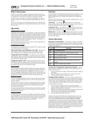
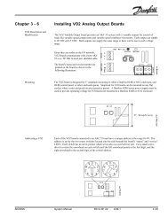
The valves are an integrated assembly of (4) modules: 1) A body, which<br />
contains no moving parts, but is ordered to suit a particular connection<br />
size; 2) A capacity cartridge, which contains both piston and modulating<br />
plug, and defines the Port Size; 3) A pilot adapter, which defines the valve<br />
BULLETIN 25-94D<br />
Type <strong>A8</strong>A, <strong>A8</strong>1, <strong>A8</strong>2<br />
August 2004<br />
Installation, Service and Parts Information<br />
function and onto which the Pilot Solenoids providing either the “S” or “B”<br />
feature are added as required; 4) The bon<strong>net</strong>, containing the Range Spring<br />
and adjustment screw, which mechanisms are set for the value of pressure<br />
which the valve is to maintain.<br />
This unique modular design allows the regulator to be soldered into the<br />
line without disassembly, yet provides full access for disassembly, cleaning<br />
and servicing from the top only. Interchangeable capacity cartridges<br />
facilitate flow revisions should an undersized or oversized condition be<br />
created, while pilot adaptors can be changed out to add features or even<br />
change functions. Thus, retrofitting for additional evaporator capacity, heat<br />
reclaim, or holdback for hot gas defrost is simple and requires no pipe line<br />
revisions under most circumstances.<br />
All <strong>A8</strong> series regulators for inlet and outlet functions feature the wide range<br />
pressure setting, 250mm Hg to 27.6 bar (10" VA. to 400 psig). Regulators<br />
for differential function have a range of 0 to 8.3 bar (0 to 120 psi).<br />
STAINLESS STEEL<br />
DIAPHRAGM<br />
FIELD ADJUSTABLE<br />
SET-POINT<br />
BONNET AS SHOWN<br />
ATTACHED TO ADAPTER<br />
SEPARABLE<br />
PISTON<br />
MANUAL<br />
OPENING STEM<br />
CONTOURED<br />
PLUG<br />
1/4” SAE FLARE<br />
ACCESS FITTING<br />
INLET PRESSURE<br />
ALL WEAR<br />
PARTS<br />
SERVICABLE<br />
FROM TOP ONLY<br />
INTERCHANCEABLE<br />
CARTRIDGE TO<br />
CHANGE CAPACITY<br />
THREE BASIC<br />
BODY SIZES<br />
MULTIPLE O.D.S.<br />
CONNECTIONS<br />
FLO-CON<br />
050263<br />
Fig.1 – <strong>A8</strong>A, <strong>A8</strong>1 Assembly (<strong>A8</strong>1 Body Shown)<br />
1<br />
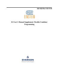
Fig.2 – <strong>A8</strong>2 Assembly<br />
I S O 9 0 0 1 - 2 0 0 0 C E R T I F I E D
PURPOSE<br />
These valves will modulate to maintain a pressure as set for in the field, in<br />
spite of fluctuations in load, changes in ambient, changes in available refrigerant<br />
flow paths, and other operating variances. Appropriately sized, these valves<br />
will modulate the flow of liquid or vapor, high side or low side in a wide variety<br />
of system arrangements used in industrial, commercial and air conditioning<br />
installations. A particular inlet regulator can be applied to control evaporator,<br />
condensate, discharge or defrost relief pressure; a particular outlet regulator<br />
can be applied to control crankcase, receiver or hot gas bypass; or a differential<br />
regulator can be applied to maintain oil receiver pressure, or discharge<br />
differential, or liquid line differential pressure. Each port size will have a specific<br />
maximum capacity at full opening corresponding to the available or sensible<br />
pressure difference under which it will operate, for each of these applications.<br />
The prefix <strong>A8</strong> defines a body or assembly style, in this case a direct-connected,<br />
O.D.S. stubbed, modular assembly, pressure regulator. The basic designations<br />
are <strong>A8</strong>A, <strong>A8</strong>1, and <strong>A8</strong>2, which, with no other suffix, define by default Inlet<br />
Pressure Regulators in the (3) available body sizes. To complete the<br />
purchasing specification for an inlet regulator with no additional features, the<br />
Port Size and Connection Size must yet be determined. For an Inlet Pressure<br />
Regulator, as the valve’s inlet pressure increases even marginally above the<br />
set-point the valve tends to open, increasing flow and reducing inlet pressure.<br />
As operating conditions change and the inlet pressure tends to drop, the valve’s<br />
port closes and the inlet pressure will tend to rise. In this fashion the valve<br />
continually adjusts its available flow area in response to flow conditions to<br />
maintain a practically constant inlet pressure.<br />
The solenoid features can be designated for these inlet pressure regulators by<br />
adding the appropriate suffix, thus <strong>A8</strong>-S for Inlet Regulator with Electric<br />
Shut-off and <strong>A8</strong>-B for Inlet Regulator with Electric Wide Opening.<br />
The suffix “O” defines a regulator whose function is to modulate flow to maintain<br />
a constant Outlet or Downstream pressure. This valve function requires that<br />
an external field installed connection be made between the pilot equalizing<br />
connection and the downstream pipe, thus the “O” designation is always<br />
accompanied by an “E” for externally equalized (<strong>A8</strong>-OE). The function now is<br />
to open and permit higher flows when outlet pressure tends to drop, and to<br />
close and reduce flow when outlet pressure tends to rise. In this fashion the<br />
valve is continuously adjusting its opening to maintain downstream pressure<br />
practically constant.<br />
The outlet pressure regulators are available with the “S” feature, thus the<br />
designation <strong>A8</strong>-OES defines an Outlet Pressure Regulator with Electric<br />
Shut-Off, which will maintain constant downstream pressure when the coil is<br />
energized, and close tightly when the coil is de-energized.<br />
The suffix “L” is added to designate a Differential Pressure Regulator. This<br />
valve function senses both Upstream and Downstream pressure and modulates<br />
to maintain the difference, practically constant. Thus the regulator responds<br />
to a rise in that pressure difference by opening the port, and responds to a<br />
drop in that difference by closing the port. An <strong>A8</strong>-L is a Differential Pressure<br />
Regulator.<br />
The Differential Pressure Regulators can all be ordered with the Wide Opening<br />
Feature, by adding the suffix “B” to the valve designation. Thus, an <strong>A8</strong>-BL is<br />
a Differential Pressure Regulator when the solenoid coil is not energized,<br />
and will open wide, providing the system flow can maintain a minimum pressure<br />
difference of 1.5 psig, once the solenoid coil is energized.<br />
The valve designation then describes the Body Size, Function, and Control<br />
Features of the Regulator. A complete specification for a regulator also includes:<br />
The Port Size: Selected according to the state and density of the refrigerant<br />
along with the sensible or available pressure difference under which the valve<br />
will operate;<br />
The Connection Size: Normally designated by the system designer, but often<br />
selected by the installer to match the line size as found in the field.<br />
Note that the particular combination of the above (2) sizes will normally indicate<br />
the appropriate body size, though there are some overlaps.<br />
The Pressure Control Function: Inlet, by default; Outlet (OE) or Differential<br />
(L), according to just what pressure, or pressure difference, the designer or<br />
installer expects the valve to regulate.<br />
The Control Features: Shut-off, “S” or Bypass “B”, as selected by the designer<br />
or the installer.<br />
AND, ONLY FOR THOSE VALVES REQUIRING THE “S” OR “B” FEATURE:<br />
The Control Circuit Voltage: As required by the installation, consists of Voltage<br />
and, for A.C. circuits, Frequency.<br />
All <strong>A8</strong> regulators will permit reverse flow if the outlet pressure exceeds the<br />
inlet pressure by more than 0.14 bar (2 psi).<br />
INSTALLATION<br />
On the Types <strong>A8</strong>A, <strong>A8</strong>1 and <strong>A8</strong>2 Series Regulators, the proper direction of<br />
flow is designated by an arrow cast into the side of the valve body, pointing<br />
from inlet to outlet.<br />
The regulator can be mounted in a horizontal or vertical pipe line with direction<br />
of flow as described above. As with all pressure regulators, these compact<br />
regulators can control flow in this normal direction only. If a change in system<br />
operating conditions causes the outlet pressure to rise sufficiently above the<br />
inlet pressure, the Main <strong>Valve</strong> Assembly may be blown down from its seat<br />
and reverse flow can occur. This is often accompanied by a clicking noise.<br />
Protect the inside of the regulator from moisture, dirt, chips and solder beads<br />
during installation. These compact regulators may be soldered into the line<br />
without disassembly if reasonable precautions are taken. The flame from the<br />
soldering torch should be directed away from the valve body to avoid excessive<br />
heat build-up which could possibly damage some of the internal parts. As an<br />
additonal precaution, a wet cloth should be wrapped around the regulator<br />
body to dissipate some of the heat during the soldering operation.<br />
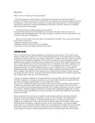
PRINCIPLES OF OPERATION<br />
(Referring to <strong>Valve</strong>s as shown in Fig. 3-9)<br />
In all cases, a throttling point serves to increase or reduce the rate of delivery<br />
of the pilot stream from the upstream side of the valve to the space on top of<br />
the piston, from which it is bled to the downstream via both a tiny hole through<br />
the piston and the clearance between piston and bore. An increased pilot<br />
stream flow increases the pressure on top of the piston which pushes the<br />
modulating plug down. Conversely, a decreased pilot stream flow reduces<br />
the pressure on top of the piston and permits the closing spring to push the<br />
modulating plug up, reducing the flow area available at the port. The pilot<br />
portion of the valve is devoted to administering this pilot stream flow, thus<br />
effectively controlling the main valve opening. The valve function (inlet, outlet,<br />
differential) is determined by the pressure condition to which the pilot aspect<br />
of the valve responds.<br />
FOR AN INLET PRESSURE REGULATOR: The inlet pressure is applied via<br />
Passage N to the underside of the #10 Diaphragm at Chamber P. Considering<br />
a valve that is initially closed, as the inlet pressure rises, the Diaphragm<br />
exerts a force upward against the #5 Range Spring. When that force developed<br />
by the inlet pressure is high enough, it will equal the spring force at that point<br />
of adjustment and the diaphragm will rise off its seat and permit flow from the<br />
upstream to Chamber G, thus raising the pressure on top of the piston, causing<br />
the Modulating Plug H to move down, and opening the port. Should the system<br />
conditions cause the upstream pressure to decrease, the Diaphragm will return<br />
to a position closer to the Pilot Seat, reducing the pilot stream flow, and<br />
allowing the pressure in Chamber G to bleed away somewhat, which permits<br />
the closing spring to move the modulating plug up, thus closing the port.<br />
FOR AN OUTLET PRESSURE REGULATOR: The external, field installed<br />
connection is run from the Fitting J to the appropriate space where the pressure<br />
is to be controlled. If this is the pressure at the outlet of the valve, then<br />
downstream pressure is communicated to the space beneath the Diaphragm<br />
#10. As outlet pressure drops, the Range Spring overcomes the force<br />
developed by the Diaphragm #10, pushing it down and opening the passage<br />
in the Pilot Seat. Thus, the pilot stream flow from the inlet side of the valve via<br />
Passage N increases, raising the pressure in Chamber G and pushing the<br />
piston and modulating plug down, causing the port to open. As downstream<br />
pressure increases, the force developed by the Diaphragm #10 increases,<br />
overcoming the range spring force, and the Pilot Passage closes, reducing<br />
pilot stream flow and the pressure at Chamber G, permitting the closing spring<br />
to move the Modulating Plug up, and reducing the available flow area.<br />
FOR A DIFFERENTIAL PRESSURE REGULATOR: The inlet pressure is<br />
applied to the underside of the Diaphragm #10 and the outlet pressure is field<br />
connected to the Fitting K on the Special bon<strong>net</strong>, such that pressure is applied<br />
to the top of the Diaphragm #10. The force applied against the range spring<br />
by the diaphragm is now due to the difference between the inlet pressure and<br />
the outlet pressure. As the inlet pressure rises to exceed the outlet pressure<br />
by more than the compressive force of the spring, the diaphragm will tend to<br />
lift and the pilot stream increase, applying more pressure to the top of the<br />
piston and increasing the port area available to flow. As conditions change<br />
and the Outlet Pressure rises to reduce the difference between inlet and outlet,<br />
the Diaphragm 10 will be pushed down toward its seat by the Range Spring,<br />
which will decrease the pilot stream flow, reduce the pressure in Chamber G<br />
and permit the closing spring to raise the modulating plug, thus reducing the<br />
available flow area.<br />
FLO-CON<br />
2
FLO-CON<br />
3
ITEM DESCRIPTION QTY FOR <strong>A8</strong>A KIT NO. FOR <strong>A8</strong>1 KIT NO. FOR <strong>A8</strong>2 KIT NO.<br />
17 Cartridge Assembly 1 Only with kit Only with kit Only with kit<br />
14, 17, 17A, 18 Cartridge Assembly (Red 5/8") 1 ea 202712 202712 —<br />
14, 17, 17A, 18 Cartridge Assembly (Full 5/8") 1 ea 202711 202711 —<br />
14, 17, 17A, 18 Cartridge Assembly (7/8") 1 ea 202710 202710 —<br />
14, 17, 17A, 18 Cartridge Assembly (1-1/8") 1 ea — 202709 —<br />
14, 17, 17A, 18 Cartridge Assembly (1-3/8") 1 ea — 202708 —<br />
17B Capacity Cartridge Housing, <strong>A8</strong>2 1 — — Only with kit<br />
14, 17A, 17B, 18, 26, 30 Complete Capacity Cartridge, 1-5/8 P. 1 ea — — 203811<br />
14, 17A, 17B, 18, 26, 30 Complete Capacity Cartridge, 2-1/8 P. 1 ea — — 203812<br />
14, 17A, 17B, 18, 26, 30 Complete Capacity Cartridge, 2-5/8 P. 1 ea — — 203813<br />
ITEM DESCRIPTION QTY FOR <strong>A8</strong>A, <strong>A8</strong>1 KIT NUMBER FOR <strong>A8</strong>2 KIT NUMBER<br />
1 Adjusting Stem (All except “L”) 1 301888 301888<br />
1A Adjusting Stem (“L” Types only) 1 Only with kit Only with kit<br />
1A, 25, 26 Adjusting Stem Kit (“L” Types only) 1 ea 201698 201698<br />
2 Adjusting Stem Seal Nut 1 301836 301836<br />
3 Bon<strong>net</strong> (All except ”L”) I Only with kit Only with kit<br />
3, 11, 8 Bon<strong>net</strong> Kit (All except ”L”) 1 ea 200910 200910<br />
3A Bon<strong>net</strong> (“L” Types only) 1 Only with kit Only with kit<br />
3A, 11, 12, 32, 33, 33A Bon<strong>net</strong> Kit (“L” Types only) 1 ea 202714 202714<br />
4 Upper Spring Rest 1 Only with kit Only with kit<br />
5 Range Spring (Outer) 1 Only with kit Only with kit<br />
5A Range Spring (Inner) 1 Only with kit Only with kit<br />
7 Lower Spring Rest 1 Only with kit Only with kit<br />
8 “O”Ring Diaphragm Follower (All except ”L”) 1 Only with kit Only with kit<br />
4, 5, 5A, 7, 8, 11 Spring Kit (All except ”L”) 1 ea 202205 202205<br />
4, 5, 7, 11 Spring Kit (“L” Types only) 1 ea 202702 202702<br />
6, 6A Bolt Package (All except ”OE and L’) <strong>A8</strong>2 4 ea — 203820<br />
6, 6A Bolt Package (“OE” Types only) <strong>A8</strong>2 4 ea — 203821<br />
6, 6A Bolt Package (“L” Types only) <strong>A8</strong>2 4 ea — 203822<br />
6 Bolt Package (All except ”OE” and “L”) <strong>A8</strong>A, <strong>A8</strong>1 4 202717 —<br />
6 Bolt Package (“OE” Types only) <strong>A8</strong>A, <strong>A8</strong>1 4 202716 —<br />
6 Bolt Package (“L” Types only) <strong>A8</strong>A, <strong>A8</strong>1 4 20271 8 —<br />
8, 11, 12, 14, 17A, Gasket/O-Ring Kit, All Types except ”L” 8 202701 203818<br />
18, 19, 37<br />
11, 12, 14, 17A, 18, 19, GaskeVO-Ring Kit ”L” Type 10 203714 203819<br />
32, 33, 33A, 37<br />
9 Diaphragm Follower 1 Only with kit Only with kit<br />
8, 9, 11 Diaphragm Follower Kit 1 ea 200911 200911<br />
(Do not use O-Ring on ”L” versions)<br />
10 Diaphragm 1 Only with kit Only with kit<br />
10, 11, 12 Diaphragm Kit 1 ea 200873 200873<br />
13 AdapterAssembly 1 Only with kit Only with kit<br />
20 Seal Cap 1 Only with kit Only with kit<br />
11, 12, 13, 14, 19, 20 Adapter Assembly <strong>A8</strong>A, <strong>A8</strong>1 Only 1 ea 202721 —<br />
11, 12, 13, 14, 19, 20, 36, 37 Adapter Assembly <strong>A8</strong>AS, <strong>A8</strong>1S Only 1 ea 202722 —<br />
11, 12, 13, 14, 19, 20, 36, 37 Adapter Assembly ASAS, <strong>A8</strong>1B Only 1 ea 202723 —<br />
11, 12, 13, 14, 19, 20, 35 Adapter Assembly <strong>A8</strong>AOE, <strong>A8</strong>1OE Only 1 ea 202720 —<br />
11, 12, 13, 14, 19, 20, 35, 36, 37 Adapter Assembly <strong>A8</strong>AOES, <strong>A8</strong>1OES Only 1 ea 202719 —<br />
11, 12, 13, 14, 19, 20 Adapter Assembly <strong>A8</strong>2 Only 1 ea — 203803<br />
11, 12, 13, 14, 19, 20, 36, 37 Adapter Assembly <strong>A8</strong>2S Only 1 ea — 203805<br />
11, 12, 13, 14, 19, 20, 36, 37 Adapter Assembly <strong>A8</strong>2B Only 1 ea — 203804<br />
11, 12, 13, 14, 19, 20, 35 Adapter Assembly <strong>A8</strong>2OE Only 1 ea — 203806<br />
11, 12, 13, 14, 19, 20, 35, 36, 37 Adapter Assembly <strong>A8</strong>2OES Only 1 ea — 203807<br />
15 Pin, Locating 2 N/A Separately N/A Separately<br />
16 Body Assembly 1 N/A Separately N/A Separately<br />
21, 22 Access Fitting and Cap 1 ea N/A Separately N/A Separately<br />
23 Self-Lock Nut 1 — Only with kit<br />
24 Washer 1 — Only with kit<br />
25 O-Ring 1 — Only with kit<br />
26 Above 3 Items —<br />
14, 17A, 18, 26 Service Kit, Piston/Plug 1 ea — 203823<br />
27 Piston 1 — Only with kit<br />
28 Closing Spring 1 — Only with kit<br />
14, 17A, 18, 26, 27, 28 Piston Kit 1 ea — 203824<br />
29 Modulating Plug 1 — Only with kit<br />
30 Items: 27, 28, 29 - — Only with kit<br />
31 Seal Cap (Only “L”) 1 Only with kit Only with kit<br />
31, 32 Seal Cap Kit (Only “L”) 1 ea 202713 202713<br />
(Discard gasket from kit)<br />
33 Retaining Ring, “L” Bon<strong>net</strong> 1 Part of 201698 Part of 201698<br />
33A O/Ring, Adjusting Stem 1 Part of 210698 Part of 210698<br />
34 1/4" SAE Flare Half-Union 1 Part of 202714 Part of 202714<br />
35A Seat, Pilot (“OE”Only) 1 Only with kit Only with kit<br />
35B O-Ring, Pilot Seat (“OE” Only) 1 Only with kit Only with kit<br />
35C Spring, Pilot Seat (“OE” Only) 1 Only with kit Only with kit<br />
10, 11, 12, 35A-C Seat Kit, Pilot (“OE” Only) 1 ea 202715 202715<br />
36 Solenoid Operator Assembly 1 Only with kit Only with kit<br />
36, 37, 38 Solenoid Operator Repair Kit 1 ea 202700 202700<br />
39 Coil 1 Only with kit Only with kit<br />
40 Sleeve, Coil Insert 2 Only with kit Only with kit<br />
41 Clip, Coil Cover 1 Only with kit Only with kit<br />
39, 40, 41 Coil and Housing Kit 120V/60; 110V/50 1 202940 202940<br />
39, 40, 41 Coil and Housing Kit 240V/60; 220V/50 1 202941 202941<br />
39, 40, 41 Coil and Housing Kit 208V/60 1 202942 202942<br />
39, 40, 41 Coil and Housing Kit 480V/60; 440V/50 1 202943 202943<br />
39, 40, 41 Coil and Housing Kit 24V/60 1 202944 202944<br />
39, 40, 41 Coil and Housing Kit 240V/50 1 202945 202945<br />
FLO-CON<br />
4
Fig. 10<br />
FLO-CON<br />
5
THE SOLENOID FEATURES: “S” for Shut-off, “B” for Bypass. To effect<br />
either of the features, a Solenoid is employed to modify the Pilot Stream at<br />
the Pilot Adapter. The Actuator is Normally Closed for both features, and<br />
can accept a variety of different coil voltages.<br />
A valve with the “S” feature will act to regulate in its normal fashion,<br />
according to its function and as set-for, when its solenoid coil is energized,<br />
and shut tightly when the solenoid coil is de-energized. The pilot solenoid<br />
is arranged such that, when closed, it will intercept the pilot stream before<br />
it reaches the throttling device, thus ensuring that the pressure on top of<br />
the Piston is the same as Downstream pressure and permitting the closing<br />
spring to close the main valve. When the Solenoid is energized, it permits<br />
the full upstream pressure to be delivered to the throttling device.<br />
A valve with the “B” feature will act to regulate in its normal fashion,<br />
according to its function and as set for, when its solenoid coil is<br />
de-energized, and will open wide when its coil is energized, providing the<br />
available flow can maintain a 1.5 psi minimum pressure difference.<br />
Now the pilot solenoid is arranged such that, when energized it bypasses<br />
the throttling device in the pilot circuit and delivers full upstream pressure<br />
to Chamber G on top of the piston, causing piston and modulating plug to<br />
move all the way down and the main valve to open wide. When de-energized<br />
the pilot stream is managed by the normal throttling device, and the regulator<br />
will maintain its set-for pressure in its normal fashion. This feature is<br />
available for the Inlet and Differential regulator functions.<br />
ADJUSTMENT<br />
Adjustment of a regulator’s set point requires that the pressure being<br />
controlled be monitored by an accurate pressure gauge. Before making<br />
any adjustments, the SEAL NUT #2 must be loosened. In all cases where<br />
the regulator is administering a pressure condition and a solenoid feature<br />
is not overriding that function, and the flow is in the normal direction, turning<br />
the ADJUSTING SCREW #1 in (i.e. clockwise) will raise the set point,<br />
and turning it out (i.e. counterclockwise) will lower the set point. Depending<br />
on system responses, the gauge may reflect some delay before a change<br />
in set point actually results in a change in the pressure being maintained.<br />
This can also sometimes be observed following the energization or<br />
de-energization of the Solenoid Features.<br />
For any Inlet Pressure Regulator, the Pressure Gauge can be connected<br />
to the Access Fitting H on the Inlet side of the regulator Cartridge Assembly<br />
#17. For an Outlet Pressure Regulator, if no system gauge is available to<br />
monitor the controlled pressure, an access fitting for the gauge will have<br />
to be incorporated into the External Equalizer. For a Differential Pressure<br />
Regulator, both upstream and remote pressure must be known before a<br />
sensible adjustment can be made. The inbuilt Access Fitting H reads only<br />
upstream pressure; the Bon<strong>net</strong> Pressure must be measured by a second<br />
gauge.<br />
For Inlet and Outlet Pressure Regulators: Between 0 and 6.2 Bar (90 psig),<br />
one complete turn of the Adjusting Screw will change the set point 1.4 Bar<br />
(20 psi). Between 6.2 Bar (90 psig) and 400 psig, one complete turn of the<br />
Adjusting Screw will change the set point 4.8 Bar (70 psi). For Differential<br />
Pressure Regulators, one complete turn of the Adjusting Screw will change<br />
the set point 1.4 Bar (20 psi) up to the maximum 8.4 Bar (120 psi)<br />
differential.<br />
CAUTION: Regulators with B features can only be adjusted with the pilot<br />
solenoid de-energized. Regulators with the S feature can only be<br />
adjusted with the solenoid energized.<br />
Always re-tighten the Seal Nut once adjustment is completed.<br />
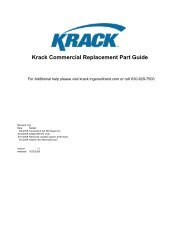
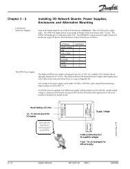
INLET<br />
<strong>A8</strong>_<br />
OUTLET<br />
<strong>A8</strong>_OE<br />
DIFFERENTIAL<br />
<strong>A8</strong>_L<br />
Fig. 11<br />
External Differences in Pilot Section;<br />
for Various Functions<br />
CONTROL CONFIGURATIONS BODY SIZE & FEATURES<br />
TYPICAL APPLICATIONS FUNCTION PORT SIZES CONNECTION SIZES (PILOT CIRCUIT) NOTE (1)<br />
INLET PRESSURE <strong>A8</strong>A 3/8", 5/8", 7/8" 5/8", 7/8", 1-1/8" Shut-Off “S”<br />
(INTEGRATED)<br />
<strong>A8</strong>AS, <strong>A8</strong>1S, <strong>A8</strong>2S<br />
Evaporator Pressure Regulator<br />
(3/8", 5/8") 1-1/8", 1-3/8", 1-5/8", 2-1/8"<br />
<strong>A8</strong>1<br />
Defrost Relief Regulator 7/8", 1-1/8", 1-3/8" Wide Opening “B”<br />
Head Pressure Control<br />
<strong>A8</strong>AB, <strong>A8</strong>1B, <strong>A8</strong>2B<br />
Heat Reclaim <strong>A8</strong>2 1-5/8", 2-1/8", 2-5/8" 1-5/8", 2-1/8", 2-5/8"<br />
OUTLET PRESSURE <strong>A8</strong>AOE 3/8", 5/8", 7/8" 5/8", 7/8", 1-1/8" Shut-Off “S”<br />
(EXTERNAL EQUALIZED)<br />
Crankcase Pressure Regulator<br />
(3/8-,5/8)” 1-1/8", 1-3/8", 1-5/8", 2-1/8" <strong>A8</strong>AOES<br />
Receiver Pressure Control<br />
<strong>A8</strong>1OE<br />
7/8", 1-1/8", 1-3/8" <strong>A8</strong>1OES<br />
Heat Reclaim<br />
<strong>A8</strong>2OES<br />
<strong>A8</strong>2OE 1-5/8", 2-1/8 “ 1-5/8”, 2-1/8", 2-5/8"<br />
-<br />
DIFFERENTIAL PRESSURE <strong>A8</strong>AL 3/8", 5/8", 7/8" 5/8", 7/8", 1-1/8" Wide-Open “B”<br />
(EXTERNAL EQUALIZED)<br />
Liquid Main Pressure Control<br />
(3/8", 5/8") 1-1/8", 1-3/8", 1-5/8", 2-1/8" <strong>A8</strong>ABL<br />
<strong>A8</strong>1L<br />
Heat Reclaim 7/8", 1-1/8", 1-3/8" <strong>A8</strong>1BL<br />
Oil Return<br />
<strong>A8</strong>2BL<br />
Liquid Overfeed Control <strong>A8</strong>2L 1-5/8", 2-1/8", 2-5/8" 1-5/8", 2-1/8", 2-5/8"<br />
FLO-CON<br />
6
DISASSEMBLY (See also Bulletin RSBCV)<br />
All <strong>A8</strong> series regulators can be disassembled and all serviceable and moving<br />
parts replaced without disturbing the piping, but of course, disassembly will<br />
cause exposure of some section of piping to atmosphere, which should be<br />
addressed before disassembly by evacuation and reclaim of the refrigerant.<br />
For the <strong>A8</strong>A and <strong>A8</strong>1 series Inlet and Outlet Pressure Regulators, the Seal<br />
Nut should be loosened and the Adjustment Screw backed out until no futher<br />
spring compression is felt. For the OE and L function valves, all external<br />
equalizers should now be carefully disconnected, taking care that any trapped<br />
refrigerant is allowed to escape slowly. For any Differential (L) Function<br />
regulator, remove the seal cap carefully to ensure all trapped refrigerant is<br />
safely vented; then back out the Adjusting Screw. For the <strong>A8</strong>2 series, if it is<br />
known that access to the Range Spring(s) #5 and Diaphragm #10 is not<br />
required, the sub-assembly from the Adapter up can remain intact and the<br />
regulator set point can thus be preserved, avoiding the need for gross<br />
adjustments when the valve is put back in service. If access to the pilot parts<br />
on an <strong>A8</strong>2 is required, then the compression must be taken off the Range<br />
Spring as described above, and the Bon<strong>net</strong> Bolts #6 removed. if a Solenoid<br />
Feature is incorporated, the Solenoid Coil #39 should now be removed by<br />
removing the Coil Cover Retaining Clamp. Never energize a Solenoid Coil<br />
that is not mounted and secured on its Solenoid Actuator #36.<br />
If the subject valve is of the <strong>A8</strong>A or <strong>A8</strong>1 series, then the 4-bolts retaining the<br />
<strong>Valve</strong> Assembly can now be removed. The bon<strong>net</strong> can be easily lifted off, and<br />
will usually leave the Diaphragm #10 resting on top of the O-Ring #12. If the<br />
valve is of the <strong>A8</strong>2 series, the bolts retaining the (3) lower sub-assemblies can<br />
now be removed. The wear aspects of the Adapter Assembly #13 are the<br />
Diaphragm #10 and the Pilot Seat, which is pressed into the top of the Adapter<br />
#13, and which may cause replacement of that Adapter. Remove the<br />
diaphragms and inspect carefully for cracks, or scarring around the pilot seat<br />
area. This is most easily done by looking down a piece of large tubing, through<br />
the diaphragm, at a safety lamp or similar light source. Inspect the Pilot Seat<br />
area of Inlet or Differential regulators for erosion or other damage; it should be<br />
dead smooth to maintain a good metal-to-metal seat. Removal of the Adapter<br />
Assembly #13 and the Cartridge Assembly #17 may require a sharp tap on<br />
their sides to unseat the parts from their sealed position, for which a rubber or<br />
rawhide hammer is recommended so as to avoid damage to the sealing<br />
surfaces.<br />
Removal of the Adapter #13 will expose the top of the piston. The top of piston<br />
space should be inspected now, and the piston pressed down by hand and<br />
permitted to return to ensure it is free. The return stroke is damped and is<br />
fairly slow, though there should be no dragging or hesitation. In the case of the<br />
<strong>A8</strong>A and <strong>A8</strong>1, the Cartridge Assembly #17 is a sealed sub-assembly which<br />
must be replaced intact, but it is of very rugged construction so, with the<br />
exception of change to valve port size with changes in flow requirements, it<br />
should not require servicing beyond basic cleaning. With the Capacity Cartridge<br />
removed from the body, depress the piston and inspect the Seating Surfaces<br />
at the Modulating Plug for deleterious material, extraordinary wear,<br />
misalignment, etc.<br />
Before re-assembly, all parts must be cleaned with a suitable solvent, permitted<br />
to dry, and lubricated with a light film of refrigerant oil, simply wiped on with<br />
the fingers, All gaskets and O-Rings should be renewed, and insertion and<br />
sealing will be facilitated if a similar film of oil is applied to them as well.<br />
Re-assembly is exactly the reverse of disassembly, with the precaution that<br />
the reliefs cut into each module of the valve assembly and the corresponding<br />
gaskets be aligned with the appropriate Locating Pin #15. Ensure that all<br />
access fittings and external equalizing lines are sealed when re-installing the<br />
corresponding parts. Adjust all torques to the values indicated by Table 1.<br />
Tighten all bolts equally to draw the assembly together evenly, to ensure<br />
properly sealing of all joints. Replace all Seal Caps as applicable. When<br />
re-adjusting following servicing, prevent excessive pressures by starting with<br />
the adjustment stems at low spring compression until the system approaches<br />
the desired operating pressures, then re-set as per “ADJUSTMENT”, above.<br />
ELECTRICAL<br />
The Refrigerating Specialties Division molded water resistant Class “H” solenoid<br />
coil is designed for long lite and powerful opening force. The standard coil<br />
housing meets NEMA 3R and 4 requirements. This sealed construction can<br />
withstand direct contact with moisture and ice. By definition, Class “H” coil<br />
construction will permit coil temperatures, as measured by resistance method,<br />
as high as 185°C. (366°F.) Final coil temperatures are a function of both fluid<br />
and ambient temperatures. The higher fluid temperatures require lower ambient<br />
temperatures so the maximum coil temperature is not exceeded. Conversely,<br />
low fluid temperatures permit higher ambient temperatures.<br />
A solenoid coil should never be energized except when mounted on its<br />
corresponding solenoid tube.<br />
The molded Class “H” coil is available from stock with most standard voltages.<br />
However, coils are available for other voltages and frequencies, as well as for<br />
direct current. Coils are also available as transformer type with a 6 volt<br />
secondary winding for use with the Refrigerating Specialties Division Pilot<br />
Light Assembly Model PLT-2. See Bulletin No. 60-20.<br />
The solenoid coil must be connected to electrical lines with volts and Hertz<br />
same as stamped on coil. The supply circuits must be properly sized to give<br />
adequate voltage at the coil leads even when other electrical equipment is<br />
operating. The coil is designed to operate with line voltage from 85% to 110%<br />
of rated coil voltage. Operating with a line voltage above or below these limits<br />
may result in coil burn-out. Also, operating with line voltage below the limit<br />
will definitely result in lowering the valve’s maximum opening pressure<br />
differential. Power consumption during normal operation will be 10.2 wafts or<br />
less. On transformer coils the 6 volt leads are always black.<br />
SAFE OPERATION (See Bulletin RSBCV)<br />
People doing any work on a refrigeration system must be qualified and<br />
completely familiar with the system and the valves involved, or all other<br />
precautions will be meaningless. This includes reading and understanding<br />
pertinent product bulletins and the current Bulletin RSB-FC prior to installation<br />
or servicing work.<br />
WARRANTY<br />
All products are warranted against defects in workmanship and materials for a<br />
period of one year from date of shipment from originating factory. This warranty<br />
is in force only when products are properly installed, field assembled,<br />
maintained and operated in use and service as specifically stated in catalogs<br />
or bulletins for normal refrigeration applications, unless otherwise approved in<br />
writing. Defective products or parts thereof, returned to the factory with<br />
transportation charges prepaid and found to be defective by factory inspection,<br />
will be replaced or repaired at the company’s option, free of charge, F.O.B.<br />
factory. Warranty does not cover products which have been altered or repaired<br />
in the field, damaged in transit, accidents, misuse or abuse. Products disabled<br />
by dirt or other foreign substances will not be considered defective.<br />
The express warranty above constitutes the only warranty of the company’s<br />
products and is in lieu of all other warranties expressed or implied, written or<br />
oral, including any warranty of merchantability or warranty of fitness for a<br />
particular purpose, and in no event is the company responsible for any<br />
consequential damages of any nature, whatsoever. No employee, agent, dealer<br />
or other person is authorized to give any warranties on behalf of the company,<br />
nor to assume, for the company, any other liability in connection with any of its<br />
products.<br />
TABLE 1 - TORQUES FOR RE-ASSEMBLY<br />
(Presumes use of New Gaskets, O-Rings)<br />
Location, Use Description (SAE) Required Torque<br />
mkg. Ft-Lbs.<br />
Cartridges: <strong>A8</strong>A, <strong>A8</strong>1 1/4"-20<br />
Bon<strong>net</strong>: <strong>A8</strong>2<br />
1.1 8<br />
Cartridges: <strong>A8</strong>2 5/16"-18 1.7 12<br />
Piston/Plug: <strong>A8</strong>2<br />
Jam Nut<br />
1.1 8<br />
Solenoid Operator (all) 0.9 6<br />
TABLE 2 - SERVICE POINTERS<br />
Symptom Probable Cause Correction<br />
Failure to open, Piston jammed due to Flush clearance space<br />
close or regulate excessive dirt. between piston and<br />
cartridge bore with refrigeration<br />
oil solvent.<br />
<strong>Valve</strong> manually open. Close manual bypass stem<br />
by turning clockwise.<br />
Adjusting stem improperly Position adjusting stem<br />
positioned:<br />
properly.<br />
a. Turned in too far. Does<br />
not open (inlet regulator).<br />
b. Not turned in far enough.<br />
Does not close (inlet regulator).<br />
Does not open<br />
(Outlet regulator).<br />
Passage “N” clogged. Clean passage “N”<br />
Pilot seat dirty or eroded. Clean and smooth pilot<br />
seat. If diaphragm is removed,<br />
replace with new<br />
gasket and O-Ring.<br />
Regulator installed Re-install regulator<br />
backwards.<br />
in proper position.<br />
System control Improper Regulator Replace cartridge with<br />
cannot be selection: one of suitable size.<br />
maintained – a. Actual load is much<br />
unstable valve lower than regulator<br />
operation. capacity.<br />
b. Actual pressure drop<br />
across valve higher than<br />
originally intended.<br />
c. Combinations of a and b.<br />
FLO-CON<br />
7
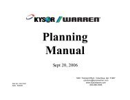
<strong>A8</strong>A - Types <strong>A8</strong>1 Types <strong>A8</strong>2 - Types<br />
4.5"<br />
114mm<br />
4.5"<br />
114mm<br />
6.4"<br />
163mm<br />
B<br />
C<br />
B<br />
C<br />
B<br />
C<br />
A<br />
A<br />
A<br />
D<br />
D<br />
E<br />
D<br />
E<br />
1.6"<br />
40mm<br />
1.4"<br />
36mm<br />
2.2"<br />
55mm<br />
1.5"<br />
38mm<br />
1.5"<br />
38mm<br />
2"<br />
50mm<br />
3.0"<br />
76mm<br />
3.0"<br />
76mm<br />
4"<br />
101mm<br />
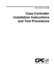
TABLE OF DIMENSIONS<br />
Type <strong>A8</strong>A (AllTypes) <strong>A8</strong>1 (All Types) <strong>A8</strong>2<br />
Connection 5/8" 7/8" 1-1/8" 1-1/8" 1-3/8" 1-5/8" 2-1/8" 1-5/8" 2-1/8" 2-5/8"<br />
Size 15 mm 22 mm 28 mm 28 mm 35 mm 42 mm 54mm 42 mm 54 mm 67 mm<br />
A<br />
Inch 7.2 7.5 8.0 8.9 9.4 9.9 11.1 11 12 13.5<br />
mm 183 190 203 226 239 251 282 279 305 343<br />
B<br />
Inch 3.9 4.0 4.3 4.5 4.7 5.0 5.6 5.9 6.4 7.1<br />
mm 99 102 109 114 119 127 142 149 162 181<br />
C<br />
Inch 0.6 0.8 1.0 1.0 1.0 1.1 1.2 1.1 1.4 1.7<br />
mm 15 20 25 25 25 28 30 28 36 44<br />
Functions <strong>A8</strong>A -S, -B -L -BL -OE,-OES <strong>A8</strong>1 -S, -B -L -BL -OE, -OES <strong>A8</strong>2 -S, -B -L -BL -OE<br />
D<br />
Inch 8.0 8.0 8.6 8.6 8.4 8.0 8.0 8.6 8.6 8.4 10.2 10.1 10.4 10.4 10.5<br />
mm 203 203 218 218 213 201 201 218 218 213 260 260 264 264 267<br />
E<br />
inch 9 9.4 10.0 10.0 9.8 9.4 9.4 10.0 10.0 9.8 12.2 12.2 12.4 12.4 12.5<br />
mm 239 239 254 254 249 239 239 254 254 249 310 310 315 315 318<br />
<strong>Parker</strong> Hannifin Corporation • Refrigerating Specialties Division<br />
2445 South 25th Avenue • Broadview, IL 60155-3891<br />
Telephone (708) 681-6300 • Fax (708) 681-6306<br />
8