Copeland Off Cycle C.. - icemeister.net
Copeland Off Cycle C.. - icemeister.net
Copeland Off Cycle C.. - icemeister.net

You also want an ePaper? Increase the reach of your titles
YUMPU automatically turns print PDFs into web optimized ePapers that Google loves.
<strong>Copeland</strong> 21-1222<br />
22-1230<br />
®<br />
®<br />
22-1230<br />
Application Engineering Bulletin<br />
AE-1230-R5<br />
Revised October 1, 1984<br />
OFF CYCLE MOTOR HEAT FOR LIQUID<br />
REFRIGERANT MIGRATION CONTROL<br />
The use of off cycle motor heat in lieu of a crankcase<br />
heater is being considered more frequently by<br />
users of single phase welded compressors, since it<br />
does offer some economies and advantages. <strong>Off</strong><br />
cycle heat essentially performs the same function as<br />
a crankcase heater. Either can offer some significant<br />
advantages in system design.<br />
It is almost impossible to entirely avoid some start<br />
up buzz on any unit where liquid can migrate to the<br />
compressor during a long off cycle. Maintaining a<br />
warm compressor can eliminate noise problems of<br />
this type.<br />
Undoubtedly the life expectancy of any compressor<br />
is affected by the number of times it is exposed<br />
to large amounts of liquid refrigerant on start up.<br />
The compressor may be able to clear the crankcase<br />
without damage under repeated test conditions, but<br />
certainly repeated stress of this nature can eventually<br />
reach the critical stage. Although it is difficult to<br />
obtain detailed long term experiences data, field<br />
experience strongly indicates that over an extended<br />
life, some type of crankcase heat can be a major<br />
factor in compressor survival on all split systems.<br />
Basically, off cycle heating is accomplished by<br />
connecting the run capacitor used for the motor heat<br />
cycle directly to the line beyond the unit disconnect<br />
rather than to the run terminal. Thus when the unit is<br />
cycled off by the thermostat, the start winding remains<br />
connected across the line through the run<br />
capacitor.<br />
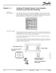
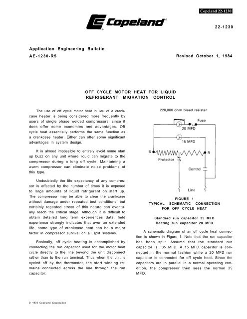
A schematic diagram of an off cycle heat connection<br />
is shown in Figure 1. Note that the run capacitor<br />
has been split. Assume that the standard run<br />
capacitor is 35 MFD. A 15 MFD capacitor is connected<br />
in the normal fashion while a 20 MFD run<br />
capacitor is connected for off cycle heat. Since the<br />
capacitors are in parallel in a normal operating condition,<br />
the compressor then sees the normal 35<br />
MFD.<br />
FIGURE 1<br />
TYPICAL SCHEMATIC CONNECTION<br />
FOR OFF CYCLE HEAT<br />
Standard run capacitor 35 MFD<br />
Heating run capacitor 20 MFD<br />
© 1972 <strong>Copeland</strong> Corporation
<strong>Copeland</strong> 21-1222 22-1230<br />
The control may be contactor or any other device<br />
that breaks the line current when the compressor<br />
is not operating.<br />
The same sort of electrical connection may be<br />
accomplished by means of a split run capacitor,<br />
which in effect is actually two capacitors in a single<br />
casing.<br />
<strong>Off</strong> cycle heat has a number of advantages and<br />
some disadvantages.<br />
1) It is not as susceptible to damage as an external<br />
crankcase heater and there is no heater element to<br />
burn out. the life expectancy of external crankcase<br />
heaters is very probably not as good as we would<br />
like to see.<br />
2) Since it is economical and compact, off cycle<br />
heat may be attractive on small package units.<br />
3) One of the side benefits of off cycle heat may be<br />
better low voltage starting characteristics. A warm<br />
stator and rotor develops more starting torque than<br />
a cold motor, and this can materially improve the<br />
compressors ability to start under marginal conditions.<br />
4) Since the off cycle heat circuit is mad through<br />
the motor protector, in the event of a protector trip,<br />
no heat is added until the protector resets. External<br />
crankcase heaters are frequently connected across<br />
the line so that they are energized continuously. On<br />
split systems where the compressor is located in an<br />
insulated compartment to reduce noise to a<br />
minimum, the reset time after a protector trip may<br />
be excessive unless the motor temperature is reduced<br />
fairly quickly. <strong>Off</strong> cycle heat would have a<br />
definite advantage over a crankcase heater in this<br />
type of situation.<br />
A major disadvantage is that the compressor is<br />
electrically energized at all times, even when the<br />
unit is off. Maintenance personnel or users may run<br />
the risk of a shock if attempting repairs without<br />
being aware of the hazard.<br />
There are at least three limiting factors that must<br />
be considered in the application of off cycle heat.<br />
1. Start winding temperatures during the off cycle<br />
heating phase must be held within safe limitations.<br />
2. Since there is no refrigerant vapor flowing to cool<br />
the motor or protector during the off cycle, the protector<br />
is sensing a different condition than that encountered<br />
during either an operating cycle or a<br />
locked rotor condition. Unless the capacitance is<br />
limited, it is possible that the protector may trip on<br />
start up due to temperature, even though the motor<br />
windings are still within safe limits.<br />
3. If start components are used, or if there is any<br />
possibility that supplementary start components<br />
may be applied in the field, the capacitance used for<br />
off cycle heat must be limited to avoid impressing<br />
excessive voltage on the start capacitor. Most manufacturers<br />
limit continuous voltage on the start<br />
capacitor to 10% of its nominal rating, with the exception<br />
of General Electric who has approved a<br />
continuous voltage of 20% of their nominal rating.<br />
In order to avoid the possibility of a dangerous<br />
electrical shock to maintenance personnel even<br />
when disconnected from power, a 220,000 ohm<br />
bleed resister must be mounted across the run<br />
capacitor used for off cycle heat.<br />
In the event of a short in the heating run capacitor,<br />
the motor protector could not prevent a start winding<br />
burn in the motor, and a fuse of the proper size<br />
must be mounted in the run capacitor for motor protection,<br />
or a fused run capacitor must be used. The<br />
necessary fuse size may be calculated as<br />
follows:<br />
l = C(E 1.2) divided by 2650<br />
l = Fuse size in amps<br />
(use next larger standard size)<br />
C = Capacitance in MFD<br />
E = Rated voltage of capacitor<br />
In the case of the example in Figure 1, assume the<br />
standard capacitor voltage rating was 370 volts.<br />
l = 20 (370 x 1.2) = 3.35 amps Use 4 amp fuse<br />
2650<br />
<strong>Copeland</strong> has approved the use of off cycle heat<br />
by several manufacturers on an individual basis.<br />
Laboratory test have indicated that off cycle heat<br />
properly applied can effectively raise the oil temperature<br />
without creating dangerous temperatures in<br />
the motor windings, and we have not encountered<br />
any field problems traceable to this type of application.<br />
2
Obviously, electrical connections are simpler if<br />
the standard run capacitor can be used for off cycle<br />
heat, without the necessity for splitting the<br />
capacitor. Extensive tests have been run in the <strong>Copeland</strong><br />
Application Engineering Laboratory to establish<br />
acceptable limits for the application of heating<br />
run capacitors.<br />
<strong>Copeland</strong> 21-1222<br />
22-1230<br />
A minimum temperature difference of 15°F between<br />
ambient temperature and oil temperature was<br />
established as the criteria as to whether off cycle<br />
heat could be effectively applied. On some smaller<br />
compressors operating on 115 volt power, insufficient<br />
heat was generated to make off cycle heating<br />
practical.<br />
In order to prevent the possibility of nuisances trips<br />
on start up in high ambient conditions, tests were<br />
run at high ambient conditions to determine<br />
stabilized compressor temperatures with various<br />
sized run capacitors. Capacitor selection has been<br />
limited to provide a maximum of 50°F temperature<br />
difference between the compressor shell temperature<br />
and ambient temperature. In general it was<br />
found that power input should be limited depending<br />
on the size of the compressor, with acceptable values<br />
varying from 25 to 75 watts.<br />
For those customers applications where tightly<br />
enclosed compressor compartments can result in<br />
temperatures surrounding the compressor remaining<br />
above 110°F for extended periods, it is essential<br />
that the manufacturer run adequate development<br />
tests to insure that a nuisance protector trip does not<br />
occur on start-up after long off periods if a<br />
maximum size run capacitor is used for off cycle<br />
heat.<br />
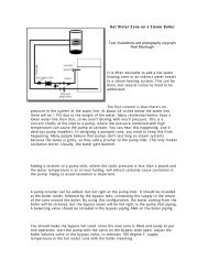
If the fan motor is wired across the line and controlled<br />
by the same single pole contactor that controls<br />
current flow to the compressor motor, a trip of<br />
FIGURE 2<br />
the motor protector can create an unexpected circuit<br />
that may allow sufficient current to flow to keep the<br />
fan motor operating. The current path is shown by<br />
the dotted line in Figure 2, through the fan motor,<br />
through both motor windings, through the off cycle<br />
heat run capacitor, and back to the line beyond the<br />
contactor contacts.<br />
It is doubtful if the current flow under such conditions<br />
is sufficient to harm the compressor motor<br />
windings, but it is possible the fan motor windings<br />
might be adversely affected, and the current flowing<br />
through the compressor motor could delay the reset<br />
of the motor protector. The only solution to this<br />
problem that has been found is the use of a two<br />
pole contactor to break the fan motor circuit as well<br />
as the compressor motor circuit.<br />
3
<strong>Copeland</strong> 21-1222 22-1230<br />
Following is a listing of Copelaweld compressors<br />
with recommendation for capacitor sizing for off<br />
cycle heat. The compressors indicated have been<br />
listed with U.L. for off cycle heat application, the U.L.<br />
listing covering the standard run capacitor as a<br />
maximum.<br />
Std. Run<br />
Capacitor<br />
MFD<br />
Maximum Run Capacitor For<br />
<strong>Off</strong> <strong>Cycle</strong> Motor Heat<br />
Model<br />
CRA1-0150-PFV 25 25<br />
CRB1-0175-PFV 25 25<br />
CRC1-0175-PFV 30 30<br />
CRD1-0200-PFV 35 35<br />
CRE1-0225-PFV 35 20<br />
CRG1-0250-PFJ 35 25<br />
CRH1-0275-PFV 40 25<br />
CRJ1-0300-PFV 35 35<br />
CRK1-0325-PFV 40 25<br />
CRL1-0350-PFV 40 25<br />
CRN1-0500-PFV 55 40<br />
®<br />
®<br />
<strong>Copeland</strong> Corporation<br />
Sidney, OH 45365-0669<br />
Printed in U.S.A.