Dixell Universal-R Installing & Operating Instructions ... - icemeister.net
Dixell Universal-R Installing & Operating Instructions ... - icemeister.net
Dixell Universal-R Installing & Operating Instructions ... - icemeister.net

Create successful ePaper yourself
Turn your PDF publications into a flip-book with our unique Google optimized e-Paper software.
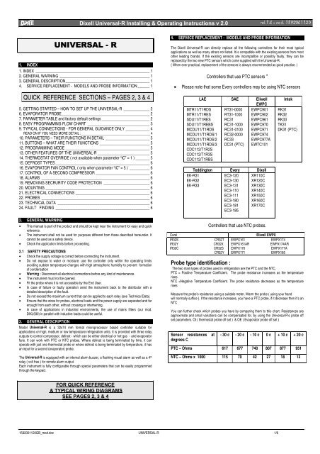
<strong>Dixell</strong> <strong>Universal</strong>-R <strong>Installing</strong> & <strong>Operating</strong> <strong>Instructions</strong> v 2.0 UHO FRG <br />
81,9(56$/5<br />
1. INDEX<br />
1. INDEX _________________________________________________________ 1<br />
2. GENERAL WARNING _____________________________________________ 1<br />
3. GENERAL DESCRIPTION__________________________________________ 1<br />
4. SERVICE REPLACEMENT - MODELS AND PROBE INFORMATION ______ 1<br />
QUICK REFERENCE SECTIONS – PAGES 2, 3 & 4<br />
5. GETTING STARTED – HOW TO SET UP THE UNIVERSAL-R _____________ 2<br />
6. EVAPORATOR PROBE____________________________________________ 2<br />
7. PARAMETER TABLE and factory default settings ________________________ 2<br />
8. EASY PROGRAMMING FLOW CHART _______________________________ 3<br />
9. TYPICAL CONNECTIONS - FOR GENERAL GUIDANCE ONLY ____________ 4<br />
READ ON IF YOU NEED MORE DETAIL :_________________________________________ 4<br />
10. PARAMETERS – THEIR FUNCTIONS IN DETAIL ______________________ 5<br />
11. BUTTONS – WHAT ARE THEIR FUNCTIONS _________________________ 5<br />
12. PROGRAMMING MODE __________________________________________ 5<br />
13. OTHER FEATURES OF THE UNIVERSAL-R __________________________ 5<br />
14. THERMOSTAT OVERRIDE ( not available when parameter “tC” = 1 ) _______ 5<br />
15. DEFROST TYPES _______________________________________________ 6<br />
16. EVAPORATOR FAN CONTROL ( only when parameter “tC” = 5 ) __________ 6<br />
17. CONTROL OF A SECOND COMPRESSOR ___________________________ 6<br />
18. ALARMS ______________________________________________________ 6<br />
19. REMOVING SECRURITY CODE PROTECTION _______________________ 6<br />
20. MOUNTING ____________________________________________________ 6<br />
21. ELECTRICAL CONNECTIONS _____________________________________ 6<br />
22. PROBES ______________________________________________________ 6<br />
23. TECHNICAL DATA ______________________________________________ 6<br />
24. FAULT FINDING _______________________________________________ 6<br />
2. GENERAL WARNING<br />
• This manual is part of the product and should be kept near the instrument for easy and quick<br />
reference.<br />
• The instrument shall not be used for purposes different from those described hereunder. It<br />
cannot be used as a safety device.<br />
• Check the application limits before proceeding.<br />
2.1 SAFETY PRECAUTIONS<br />
• Check the supply voltage is correct before connecting the instrument.<br />
• Do not expose to water or moisture: use the controller only within the operating limits<br />
avoiding sudden temperature changes with high atmospheric humidity to prevent formation<br />
of condensation<br />
• Warning : Disconnect all electrical connections before any kind of maintenance.<br />
• The instrument must not be opened.<br />
• Fit the probe where it is not accessible by the End User.<br />
• In case of failure or faulty operation send the instrument back to the distributor with a<br />
detailed description of the fault.<br />
• Do not exceed the maximum current that can be applied to each relay (see Technical Data).<br />
• Ensure that the wires for probes, electrical loads and the power supply are separated and far<br />
enough from each other, without crossing or intertwining.<br />
• In case of applications in industrial environments, the use of mains filters (our mod.<br />
DIXL930) in parallel with inductive loads could be useful.<br />
3. GENERAL DESCRIPTION<br />
Model <strong>Universal</strong>-R is a 32x74 mm format microprocessor based controller suitable for<br />
applications on high, medium or low temperature refrigeration units. It is provided with three relay<br />
outputs to control compressor, defrost - which can be either electrical or hot gas - and evaporator<br />
fans. It can work with PTC or NTC probes. Where defrost is being terminated by time, it can<br />
operate with just one thermostat probe or where defrost is being terminated by temperature, it has<br />
an input for a second (evaporator) probe.<br />
The <strong>Universal</strong>-R is equipped with an internal alarm buzzer, a flashing visual alarm as well as a 4 th<br />
relay ( volt free ) for remote alarm output.<br />
Each instrument is fully configurable through special parameters that can be easily programmed<br />
through the keypad.<br />
4. SERVICE REPLACEMENT - MODELS AND PROBE INFORMATION<br />
The <strong>Dixell</strong> <strong>Universal</strong>-R can directly replace all the following controllers for their most typical<br />
applications as well as many others not listed. It is compatible with the existing sensors from most<br />
other leading brands. If the existing sensors are incompatible or possibly faulty, they can be<br />
replaced by the two new PTC sensors which come supplied with the <strong>Universal</strong>-R.<br />
( When ever practical, replacement of the sensors is always recommended as good practise. )<br />
Controllers that use PTC sensors *<br />
• Please note that some Every controllers may be using NTC sensors<br />
LAE SAE Eliwell<br />
EWPC<br />
MTR11/T1RDS RT31-0000 EWPC901<br />
MTR11/T1RES RT31-1000 EWPC902<br />
SDU11/T1RES RC31 EWPC961<br />
SDU11/T1REBS RC31-1000 EWPC970<br />
MCDU11/T1RDS RC31-0100 EWPC971<br />
MCDU11/T1RDS/1 RC32-0000 EWPC974<br />
MCDU11/T1RDS/2 RC33 EWPC977A<br />
MCDU11/T1RDS/3 DC31 (PTC) EWTC101<br />
CDC112/T1R2S<br />
CDC112/T1R3S<br />
CDC112/T1RBS<br />
Teddington Every <strong>Dixell</strong><br />
EK-R31<br />
EK-R32<br />
EK-R33<br />
EC3-120<br />
EC3-130<br />
EC3-131<br />
EC3-110<br />
EC3-111<br />
EC3-180<br />
EC3-181<br />
EC3-185<br />
XR110C<br />
XR120C<br />
XR130C<br />
XR140C<br />
XR150C<br />
XR160C<br />
XR170C<br />
Controllers that use NTC probes.<br />
Intek<br />
RK31<br />
RK32<br />
RK33<br />
TK31<br />
DK31 (PTC)<br />
CarelEliwell EWPX<br />
IR32S<br />
CR32T EWPX161<br />
EWPX174<br />
IR32Y<br />
CR32X EWPX161AR<br />
EWPX174AR<br />
IR32C<br />
CR32S EWPX170<br />
EWPX177A<br />
CR32Y EWPX171<br />
EWPX185<br />
Probe type identification :<br />
The two main types of probes used in refrigeration are the PTC and the NTC.<br />
PTC = Positive Temperature Coefficient. The probe resistance increases as the temperature<br />
rises.<br />
NTC =Negative Temperature Coefficient. The probe resistance decreases as the temperature<br />
rises<br />
Measure the probe’s resistance using a suitable meter. Warm the probe ( using your hand<br />
will normally suffice ). If the resistance increases, you have a PTC probe, if it decrease then it’s an<br />
NTC<br />
You can further check which probes you have by comparing them to this chart. Resistances are<br />
approximate and small variations can be compensated for, by using the <strong>Universal</strong>-R’s probe off<br />
set parameters. Ot ( thermostat probe off set ) & OE ( Evaporator probe off set )<br />
Sensor resistances at<br />
degrees C<br />
- 30 c - 20 c - 10 c 0 c + 10 c + 20 c<br />
PTC – Ohms 617 677 740 807 877 951<br />
NTC – Ohms x 1000 115 70 42 27 18 12<br />
FOR QUICK REFERENCE<br />
& TYPICAL WIRING DIAGRAMS<br />
SEE PAGES 2, 3 & 4<br />
1592001120GB_mod.doc UNIVERSAL-R 1/6
<strong>Dixell</strong> <strong>Universal</strong>-R <strong>Installing</strong> & <strong>Operating</strong> <strong>Instructions</strong> v 2.0 UHO FRG <br />
QUICK REFERENCE SECTIONS – PAGES 2, 3 & 4<br />
5. GETTING STARTED – HOW TO SET UP THE UNIVERSAL-R<br />
Most 32 x 74mm refrigeration controllers fall into 1 of 5 types. The <strong>Universal</strong>-R has a smart<br />
parameter ( tC ) which programs it to operate as any of these types using settings 1 to 5<br />
UNIVERSAL R<br />
Type (category) of<br />
controller<br />
Label<br />
Adjustment<br />
Range<br />
tC 1 = On / Off Thermostat 1<br />
2 = Off cycle defrost 2<br />
Factory defaults with parameter “tC” 1 - 5<br />
3 = Time / time defrost 3<br />
Parameter<br />
TYPE OF CONTROLLER<br />
“tC” Setting<br />
1 An on / off refrigeration thermostat - 1 relay & 1 probe<br />
2 A combined thermostat and off cycle defrost timer - 1 relay & 1<br />
probe<br />
3<br />
A combined thermostat with time initiated & time terminated<br />
forced defrost -<br />
2 relays & 1 probe<br />
4 A combined thermostat with time initiated & temperature<br />
terminated forced defrost - 2 relays & 2 probes<br />
5 A combined thermostat with time initiated & temperature<br />
terminated forced defrost + evaporator fan control with delay after<br />
defrost - 3 relays & 2 probes<br />
NOW JUST FOLLOW THESE 4 SIMPLE STEPS :-<br />
Identify which type of controller you are replacing.<br />
Change over the wiring in accordance with the appropriate “Typical wiring layout”*<br />
Check the probe type in use, parameter PbC will allow you to configure the controller for<br />
PTC or NTC probes<br />
Program the <strong>Universal</strong>-R parameters using<br />
Section 7. Parameter Table &<br />
Section 8. Easy Programming Flow Chart<br />
* Always check the wiring diagram on the controller being replaced. Wiring change over guides<br />
covering most popular models of controller, are available on request from your <strong>Universal</strong>-R<br />
supplier. “Typical wiring layouts” are intended for general guidance only<br />
6. EVAPORATOR PROBE<br />
If parameter “tC” is on settings 1, 2 or 3, there is no need to fit an evaporator probe.<br />
7. PARAMETER TABLE and factory default settings<br />
IMPORTANT : Always set parameter “tC” first. As you move “tC” between settings<br />
1 to 5, all non- relevant parameters will become masked out and critical parameters Idf, MdF, Fdt<br />
& FnC will automatically revert to their factory defaults shown below. Once “tC” has been set<br />
correctly, you can then alter any other parameter if you need to.<br />
Note : If you alter the setting of parameter rES ( decimal point on / off ) re-check the settings of all<br />
temperature related parameters – Set Point, HY, LS, US, ALU, ALL, dtE, FSt, Ot & OE, as they<br />
can be effected.<br />
WARNING!!<br />
Always switch the power OFF then ON at the end of programming to initiate changes.<br />
If parameter “tC” is set to 4 or 5 without an evaporator probe fitted, a P2 probe alarm will<br />
be generated. If you do intend to use settings 4 or 5 fit a probe, if you intend to use settings<br />
1, 2 or 3, you must switch the power OFF then ON again to clear the alarm.<br />
4 = Time / temp defrost 4<br />
5 = Time / temp defrost +<br />
fan delay<br />
Probe type PbC 0 = PTC<br />
0 0 0 0 0<br />
1 = NTC<br />
Differential HY 0.2 ÷ 30.0 °c 2.0 2.0 2.0 2.0 2.0<br />
Minimum Set Point LS - 50 °c ÷ Set Point -30.0 -30.0 -30.0 -30.0 -30.0<br />
limit<br />
Maximum Set Point US Set Point ÷ 150 °c 20.0 20.0 20.0 20.0 20.0<br />
limit<br />
Anti-short cycle AC 0 ÷ 30 mins. 1 1 1 1 1<br />
delay<br />
Temperature alarm ALC 0 = Relative to SP 1 1 1 1 1<br />
configuration<br />
1 = Absolute<br />
High temperature ALU 0 ÷ 50 °c (Relative) 50 50 50 50 50<br />
alarm<br />
ALL÷150 °c (Absolute)<br />
Low temperature ALL 0 ÷ 50 °c (Relative) - 50 - 50 - 50 - 50 - 50<br />
alarm<br />
- 50 °c ÷ ALU (Absolute)<br />
Temperature alarm Ald 0 ÷ 250 mins. 15 15 15 15 15<br />
delay<br />
Delay of temperature dAO 0 ÷ 720 mins. 90 90 90 90 90<br />
alarm at start up<br />
Outputs activation OdS 0 ÷ 250 mins. 0 0 0 0 0<br />
delay at start up<br />
Thermostat override CCT 0 ÷ 990 mins. 0 0 0 0<br />
Defrost delay after dAF 0 ÷ 250 mins. 2 2 2 2<br />
thermostat override<br />
Interval between IdF 1 ÷ 250 hours 4 6 6 6<br />
defrosts<br />
Delay start of defrost dSd 0 ÷ 59 mins. 0 0 0 0<br />
( Maximum ) duration MdF 0 ÷ 250 mins. 15 15 30 30<br />
of defrost<br />
Defrost termination dtE - 50 ÷ 150 °c 8.0 8.0<br />
temperature<br />
Display during dFd 0 = Real temp.<br />
3 3 3 3<br />
defrost<br />
1 = Temp. at defrost start<br />
2 = Set Point<br />
3 = “DEF” label<br />
4 = “DEG” label<br />
Defrost display time dAd 0 ÷ 250 mins. 10 10 10 10<br />
out<br />
Defrost type ( forced tdF 0 = Electrical<br />
0 0 0<br />
)<br />
1 = Hot Gas<br />
Drain down time Fdt 0 ÷ 60 mins. 0 0 2<br />
First defrost after dPO 0 = Immediate<br />
1 1 1 1<br />
power on<br />
1 = After normal interval<br />
Evaporator fan FnC 0 ÷ 4<br />
1<br />
operating mode<br />
( 1 = Fan always on<br />
apart from during defrost.<br />
See section 10 for info.<br />
on other settings )<br />
Evaporator fan stop FSt - 50 ÷ 150 °c 25<br />
temperature<br />
Evaporator fan delay Fnd 0 ÷ 250 mins. 7<br />
after defrost<br />
Thermostat probe Ot - 12.0 ÷ 12.0 °c 0.0 0.0 0.0 0.0 0.0<br />
calibration<br />
Evaporator probe OE - 12.0 ÷ 12.0 °c 0.0 0.0<br />
calibration<br />
Display Resolution rES 0 = With decimal point 0 0 0 0 0<br />
1 = No decimal point<br />
Temperature<br />
CF 0 = ° Celsius 0 0 0 0 0<br />
measurement unit<br />
1 = ° Fahrenheit<br />
(°C/°F)<br />
Compressor ON time COn 0 ÷ 250 mins. 15 15 15 15 15<br />
with faulty probe<br />
Compressor OFF COF 0 ÷ 250 mins. 30 30 30 30 30<br />
time with faulty<br />
probe<br />
Alarm muting tbA 0 = Mute buzzer only 1 1 1 1 1<br />
configuration for<br />
1 = Mute buzzer & relay<br />
buzzer & relay<br />
Parameter table Ptb For factory use only - - - - -<br />
5<br />
Software<br />
number<br />
Evaporator<br />
temperature<br />
release<br />
probe<br />
rEL Read only - - - - -<br />
Prd Read only - - - - -<br />
1592001120GB_mod.doc UNIVERSAL-R 2/6
<strong>Dixell</strong> <strong>Universal</strong>-R <strong>Installing</strong> & <strong>Operating</strong> <strong>Instructions</strong> v 2.0 UHO FRG <br />
8. EASY PROGRAMMING FLOW CHART<br />
Read Notes<br />
Power On<br />
Enter programming mode by pressing the SET &<br />
buttons together for 3 seconds. The display will<br />
then show the first label, normally Pr2<br />
If necessary, use the & buttons<br />
to display the Pr2 label then press the “SET” button.<br />
The display will flash “PAS” and then the left hand<br />
digit will flash. Input security code ( 3-2-1) using<br />
& and “SET” buttons as follows :-<br />
3 → SET → 2 → SET →1→SET<br />
You have now entered the Pr2 security<br />
protected programming level and the first<br />
parameter’s label will be displayed, which<br />
will be “tC” ( type of controller )<br />
Press “SET” button to display setting.<br />
IMPORTANT :<br />
Whenever the setting of parameter “tC” is altered,<br />
factory defaults for parameters Idf, Mdf, Fdt & FnC<br />
are restored. For this reason, always set parameter<br />
“tC” first before attempting to alter any of the other<br />
parameters.<br />
If no button is pressed for 15 seconds, the controller<br />
will revert to normal temperature display. Any<br />
alteration that has been made will be stored.<br />
<strong>Universal</strong>-R uses a programming logic, which prevents<br />
parameters conflicting with each other.<br />
Example :<br />
If the Set Point was set at + 2°c and you tried to lower<br />
the Upper Set Point Limit ( parameter “US” ), the<br />
minimum setting the controller would allow would be<br />
+2°c. Only by lowering the Set Point could you then<br />
adjust this parameter further downwards.<br />
Is the setting correct ?<br />
Yes No<br />
Press “SET” to view<br />
next parameter label.<br />
Press “SET” again to<br />
view it’s setting<br />
Use & to alter setting. Press<br />
“SET” to store new setting and move<br />
on to next parameter’s label. Press<br />
“SET” to display it’s setting.<br />
And finally, switch the controller off then on<br />
again to initiate all the changes with<br />
immediate effect.<br />
Have all the required parameters<br />
now been correctly set ?<br />
NoYes<br />
Wait 15 seconds to<br />
“time out”. Display<br />
will revert to normal<br />
temperature<br />
display<br />
Now set the SET POINT by pressing “SET”<br />
button for 3 seconds until the LED’s at the<br />
top of the display start flashing. Use the<br />
& buttons to alter setting. Press “SET”<br />
to store the new setting.<br />
1592001120GB_mod.doc UNIVERSAL-R 3/6
<strong>Dixell</strong> <strong>Universal</strong>-R <strong>Installing</strong> & <strong>Operating</strong> <strong>Instructions</strong> v 2.0 UHO FRG <br />
9. TYPICAL CONNECTIONS - FOR GENERAL GUIDANCE ONLY<br />
Parameter tC = 1 or 2<br />
On / Off thermostat or Off Cycle Defrost Controller<br />
Parameter tC = 4<br />
Forced defrost controller, time initiated &<br />
temperature terminated.<br />
Parameter tC = 3<br />
Forced defrost controller, time initiated & time<br />
terminated.<br />
Parameter tC = 5<br />
Forced defrost controller, time initiated &<br />
temperature terminated with evaporator fan delay<br />
after defrost.<br />
READ ON IF YOU NEED MORE DETAIL :<br />
1592001120GB_mod.doc UNIVERSAL-R 4/6
<strong>Dixell</strong> <strong>Universal</strong>-R <strong>Installing</strong> & <strong>Operating</strong> <strong>Instructions</strong> v 2.0 UHO FRG <br />
10. PARAMETERS – THEIR FUNCTIONS IN DETAIL<br />
tC Type of Controller : Tells the <strong>Universal</strong>-R which type of controller it will be operating as.<br />
1 = On / Off refrigeration thermostat – 1 relay &1 probe<br />
2 = Combined thermostat with off cycle defrost timer – 1 relay & 1 probe<br />
3 = Combined thermostat with time initiated & time terminated defrost – 2 relays & 1 probe<br />
4 = Combined thermostat with time initiated & temperature terminated defrost – 2 relays & 2<br />
probes<br />
5 = Combined thermostat with time initiated, temperature terminated defrost + evaporator fan<br />
control with delay after defrost – 3 relays & 2 probes<br />
PbC Probe Type : Configures the controller to work with PTC or NTC probes.<br />
0 = PTC, 1 = NTC<br />
Hy Differential : ( 0,2°C ÷ 12,0°C ) - Sets the degrees above Set Point at which the compressor<br />
cuts in.<br />
LS Minimum set point limit : ( -50°C ÷ SET ) - Sets the lower limit of set point adjustment.<br />
US Maximum set point limit : ( SET °÷ 150°C ) - Sets the upper limit of set point adjustment<br />
AC Anti-short cycle delay : (0 ÷ 30 min) minimum interval between the compressor stop and<br />
the next possible restart.<br />
ALC Temperature alarm configuration :<br />
0 = Related to Set Point<br />
1 = Absolute<br />
Note : Related means alarms are linked to the Set Point and will follow it if it is adjusted. In<br />
this case ALU & ALL set degrees over & under Set Point for alarm. Absolute means ALU &<br />
ALL will set fixed alarm temperatures, which are not effected by any Set Point adjustment.<br />
ALU High temperature alarm : ALC = 0 from 0 ÷ 50°C; ALC = 1 from ALL ÷ 150°C<br />
ALL Low temperature alarm : ALC = 0 from 0 ÷ 50°C; ALC = 1 from -50°C ÷ ALU<br />
ALd Temperature alarm delay : (0 ÷ 250min) time interval between an alarm condition occurring<br />
and the alarm signalling.<br />
dAO Delay of temperature alarm at start-up : (from 0 ÷ 720 min; res. 10min) time delay of any<br />
temperature alarm during pull down following “power on”.<br />
OdS Outputs activation delay at start up: (0 ÷ 250min) Time delay before any output relay<br />
activates following “power on”.<br />
CCt Thermostat override : (0 ÷ 990min; res. 10 min) Period during which the compressor will<br />
run continuously, irrespective of temperature. Setting this parameter to 0 prohibits this<br />
function.<br />
dAF Defrost delay after fast freezing : ( 0 ÷ 250 min ) time interval between the end of the<br />
thermostat override period and the start of the following defrost related to it.<br />
IdF Interval between defrosts : ( 1 ÷ 250 hours ) Time interval between the beginning of two<br />
consecutive defrosts.<br />
dSd Delay start of defrost :( 0 ÷ 59min ) Delay between reaching the defrost interval time ( as<br />
defined by parameter IdF ) and the defrost actually starting. Used to stagger defrosts<br />
between multiple systems.<br />
MdF (Maximum) duration of defrost :( 0 ÷ 250 min ) Time duration of defrost when only one<br />
probe is in use, or defrost time out override when second ( evaporator ) probe is in use.<br />
dtE Defrost termination temperature : (-50 ÷150°C ) Sets the defrost termination temperature.<br />
Measured by the evaporator probe.<br />
dFd Display during defrost : 0 = real temperature; 1 = temperature at defrost start; 2 = set<br />
point; 3 = “dEF” label; 4 = “dEG” label<br />
dAd Defrost display time out : (0 ÷ 250 min). After a defrost, the controller will revert to current<br />
temperature display when the temperature is back down within it’s normal working range, or<br />
after the time set in this parameter, which ever is the sooner.<br />
tdF Defrost type : 0 = electrical heater 1 = hot gas. If set for hot gas, compressor runs during<br />
defrost.<br />
Fdt Drain down time : ( 0 ÷ 60min ) Drain down time. Runs concurrently with Fdt (Fan delay<br />
time )<br />
dPO First defrost after power-on : (0 = Immediately; 1 = after the IdF interval time)<br />
FnC Fan operating mode : 0 = cycles on / off with the compressor, OFF during defrost; 1 =<br />
continuous mode, OFF during defrost; 2 = cycles on / off with the compressor, ON during<br />
defrost; 3 = continuous mode, ON during defrost; 4 = fan relay is used as 2 nd compressor<br />
output<br />
FSt Fan stop temperature : (-50 ÷ 150°C) Temperature above which the evaporator fan stops (<br />
during the normal refrigeration cycle )<br />
Fnd Fan delay after defrost: (0 ÷ 250 min) The time interval between end of defrost and<br />
evaporator fans starting. Runs concurrently with Fdt ( Drain time ). Always keep Fnd longer<br />
that Fdt.<br />
Ot Thermostat probe calibration : ( -12.0 ÷ 12.0°C ) Adjustment for thermostat probe offset.<br />
OE Evaporator probe calibration : (-12.0 ÷ 12.0°C) Adjustment for evaporator probe offset.<br />
rES Display resolution : 0 = With decimal point, 1 = Without decimal point<br />
CF Temperature measurement unit : 0 = Celsius; 1 = Fahrenheit.<br />
Warning : If you alter the setting of parameter rES ( decimal point on / off ) re-check the<br />
settings of all temperature related parameters – Set Point, HY, LS, US, ALU, ALL, dtE, FSt,<br />
Ot & OE, as they can be effected<br />
COn Compressor ON time with faulty probe (0 ÷ 250 min) Emergency control if the thermostat<br />
probe fails. This is the compressor “ON” time.<br />
COF Compressor OFF time with faulty probe (0 ÷ 250 min) Emergency control if the<br />
thermostat probe fails. This is the compressor “OFF” time.<br />
tbA Alarm muting : 0 = Alarm relay remains active when alarm buzzer is muted. 1 = Alarm<br />
relay is cancelled when alarm buzzer is muted.<br />
Ptb Parameter table : Read only – for factory use<br />
rEL Software release : Shows the software release number<br />
Prd Evaporator probe : Shows the current temperature sensed by the evaporator probe<br />
11. BUTTONS – WHAT ARE THEIR FUNCTIONS<br />
11.1 INDIVIDUAL BUTTON FUNCTIONS<br />
SET : Display current Set Point - Press and release the SET button and the Set Point is<br />
displayed for 5sec. This will not allow the Set Point to be altered.<br />
To alter the Set Point - Hold the button pressed for at least 2sec, Set Point change<br />
mode is entered indicated by the small LED’s flashing. Change the Set Point using the<br />
X and W buttons. The new value can be stored either by pressing the “SET” button (the<br />
instrument restores temperature display) or by waiting the exit time-out to expire (15sec).<br />
X<br />
W<br />
(UP): Used to scroll through parameter labels or to increase parameter settings. Keep<br />
pressed for a faster change. Also used to initiate Thermostat override. ( See section 13,<br />
Fast Chill / Freeze )<br />
(DOWN): Used to scroll through the parameter labels or to decrease parameter<br />
settings. Keep pressed for a faster change.<br />
Manual Defrost: Press this button for 3sec. A manual defrost cycle will start and the<br />
defrost LED will illuminate. ( Not possible if parameter “tC” = 1 )<br />
COMBINATION BUTTON FUNCTIONS<br />
X + W Lock & unlock the buttons: Pressing these together for 3secs. will lock or unlock<br />
them. The display will flash “POF” or “POn for a few seconds to confirm locking or unlocking<br />
respectively.<br />
SET + W Enter programming mode: Keep both buttons pressed for 3secs. and<br />
programming mode is entered. The first label is displayed<br />
SET + X Exit programming mode: Press together to return to normal display<br />
12. PROGRAMMING MODE<br />
To enter programming mode, press the SET & W together for a few seconds, until the first label<br />
is displayed. Pr2 is normally the only label you will see here. If not, use the<br />
X or W button to scroll to the Pr2 label. Pr2 is a sub-menu containing all parameters.<br />
Now press SET. The display briefly flashes “PAS”, asking for the pass code, which is :-<br />
3 2 1<br />
Then the digits will change and start flashing “0 - - “. Starting with the left hand digit, enter the<br />
pass code using the X , W and SET buttons as follows,<br />
3 → SET → 2 → SET → 1 → SET<br />
The first parameter “tC” will now be displayed. Press SET to see it’s value, use the<br />
X & W buttons to alter the value, press SET to store it and move on to the next parameter.<br />
Always set “tC” first before setting the other parameters.<br />
Note : If you remove the security code protection from any of the parameters, their labels will<br />
appear in this first level and their values can be viewed and altered without using the security<br />
code.( See section 18, Removing Security Protection )<br />
12.1 EXIT TIME OUT - IMPORTANT<br />
If no button is pressed for 15 seconds, any alteration will be stored and the display returns to<br />
normal<br />
13. OTHER FEATURES OF THE UNIVERSAL-R<br />
13.1 LED’S<br />
As well as the main digital display, there are some small<br />
LED’s with symbols on the front panel. These are used<br />
to monitor the loads controlled by the instrument. Each<br />
LED’s function is described in the following table.<br />
LED MODEFunction<br />
ONCooling enabled<br />
&<br />
Alarm<br />
FLASHING Anti-short cycle delay in progress<br />
ONFan enabled<br />
FLASHING You are in programming mode<br />
ONDefrost in progress<br />
FLASHING Drip time in progress<br />
ONThermostat override enabled<br />
ON ALARM signal, or :- When in programming mode, in Pr2, if this<br />
lights up, it indicates that parameter is also accessible without<br />
security code, in the first level<br />
14. THERMOSTAT OVERRIDE ( not available when parameter “tC” = 1 )<br />
For rapid chilling or freezing, the thermostat can be overridden by pressing the X button until the<br />
LED under the symbol lights up. The compressor will run in continuous mode, irrespective of<br />
temperature, for the time period set in parameter “CCt”. Normal operation will then resume<br />
1592001120GB_mod.doc UNIVERSAL-R 5/6
<strong>Dixell</strong> <strong>Universal</strong>-R <strong>Installing</strong> & <strong>Operating</strong> <strong>Instructions</strong> v 2.0 UHO FRG <br />
automatically. The cycle can also be terminated manually by pressing the X button again for<br />
about 3 seconds.<br />
15. DEFROST TYPES<br />
Parameter “tC” = 1<br />
No defrost<br />
Parameter “tC” = 2<br />
Off cycle defrost by timer<br />
Parameter “tC” = 3, 4 or 5<br />
Forced defrost, Electrical or Hot Gas<br />
Parameter “tdF” = 0 defrost is electrical – “tdF” = 1 defrost is by hot gas<br />
16. EVAPORATOR FAN CONTROL ( only when parameter “tC” = 5 )<br />
The fan control mode is selected by means of the “FnC” parameter:<br />
FnC=0 fans will cycle ON and OFF with the compressor and be off during defrost:;<br />
FnC=1 fans will run continuously, but be off during defrost<br />
FnC=2 fans will switch ON and OFF with the compressor and be on during defrost *<br />
FnC=3 fans will run continuously and be on during defrost *<br />
* Note : Fans will stop if the temperature in parameter FSt is exceeded.<br />
Parameter “FSt” sets the fan stop temperature. This is the maximum temperature, detected by<br />
the evaporator probe, above which the evaporator fans will stop.<br />
Leave “FSt” above ambient during commissioning to avoid fan short cycle.<br />
After defrost, there is a stand still drain time, set by parameter “Fdt” When this period has<br />
expired, the refrigeration cycle commence but the evaporator fans remain off until “Fnd” ( fan<br />
delay ) times out.<br />
17. CONTROL OF A SECOND COMPRESSOR<br />
If the evaporator fan relay is not being used, the <strong>Universal</strong>-R can control a second compressor<br />
with this relay, using parameter “FnC”. Parameter “Fnd” ( normally used for fan delay ) now<br />
becomes the delay between the starting of compressor 1 and 2.<br />
FnC = 4 The evaporator fan relay is used to control the second compressor<br />
Fnd = 0 to 250 (minutes) Time delay between the start of the 1 st and 2 nd compressors.<br />
18. ALARMS<br />
Message – Mode Cause Outputs<br />
“EE” Flashing Data or memory failure Alarm output ON; Other outputs<br />
unchanged<br />
“P1”Flashing Thermostat probe failure Alarm output ON; Compressor output<br />
according to parameters “COn” and<br />
“COF”<br />
“P2”<br />
Alternating with room<br />
temperature<br />
“HA”<br />
Alternating with room<br />
temperature<br />
“LA”<br />
Alternating with room<br />
temperature<br />
Evaporator probe failure Alarm output ON; Other outputs<br />
unchanged; End defrost is timed<br />
High temperature alarm Alarm output ON; Other outputs<br />
unchanged.<br />
Minimum<br />
alarm<br />
temperature<br />
Alarm output ON; Other outputs<br />
unchanged.<br />
18.1 MUTING ALARM BUZZER & RELAY<br />
The alarm buzzer can be muted, by pressing any button. The controller will briefly show the reset<br />
“rES” label. Parameter tbA defines how the alarm relay will respond to the muting of the buzzer.<br />
tbA = 0 The alarm relay will remain active until the alarm condition is rectified<br />
tbA = 1 The alarm relay de-activates when the buzzer is muted<br />
In either case, the display will flash an alarm label until the condition is rectified<br />
18.2 ALARM “EE”<br />
The <strong>Dixell</strong> <strong>Universal</strong>-R is provided with an internal watchdog verifying data and memory integrity.<br />
Alarm “EE” flashes when a failure in data or in the internal memory is detected. In such case the<br />
alarm output is enabled.<br />
WHAT TO DO<br />
1. Cancel the alarm by pressing a key.<br />
2. Check the value of all parameters and restore correct values when wrong.<br />
3. Check the correct instrument operation and in case of further errors replace it.<br />
18.2.1 ALARM RECOVERY<br />
Probe alarms “P1” and “P2” start 30 seconds after a fault in probe is detected; they automatically<br />
stop 30 seconds after the probe restarts normal operation. Check connections before replacing the<br />
probe.<br />
Temperature alarms “HA” and “LA” automatically stop as soon as the thermostat temperature<br />
returns to normal values and when defrost starts.<br />
19. REMOVING SECRURITY CODE PROTECTION<br />
It is possible to allow access to any parameter without using the security code. To do this, go into<br />
Pr2 as previously described. Scroll to the label of the parameter you require and then press the<br />
SET and W buttons in quick succession. The small alarm LED will light up indicating that access<br />
to this particular parameter is now possible without the security code. It’s label will now appear<br />
when you are in the first programming level and it’s value can be altered. Remove access using<br />
the same procedure and the LED will go out.<br />
20. MOUNTING<br />
The <strong>Universal</strong>-R should be mounted in a panel, in a 29 x 71 mm hole, and fixed using the special<br />
brackets supplied.<br />
Ambient temperature for correct operation is 0 - 60 °C. Avoid places subject to strong vibrations,<br />
corrosive gases, excessive dirt or humidity, 20 – 85% non condensing. Make sure air can freely<br />
circulate through the cooling holes slots at the back of the controller.<br />
21. ELECTRICAL CONNECTIONS<br />
The instrument is provided with screw terminal block to connect cables with a cross section up to<br />
2,5 mm 2 . Before connecting cables make sure the power supply complies with the instrument’s<br />
requirements. Separate the probe cables from the power supply cables, from the outputs and the<br />
power connections. Do not exceed the maximum current rating for each relay, in case of heavier<br />
loads use a suitable external relay.<br />
22. PROBES<br />
It is recommended to place the thermostat probe away from rapid air streams to correctly measure<br />
the average room temperature. Place the defrost termination probe among the evaporator fins in<br />
the coldest place, where most ice is formed, far from heaters or from the warmest place during<br />
defrost, to prevent premature defrost termination.<br />
23. TECHNICAL DATA<br />
ousing:<br />
Self extinguishing ABS.<br />
Size :<br />
Frontal 32x74 mm; depth 70mm;<br />
Mounting :<br />
Panel mounting in a 71x29 mm panel cut-out.<br />
Frontal protection : IP65<br />
Connections:<br />
Screw terminal block ≤ 2,5 mm 2 wiring.<br />
Power supply : 12Vac/dc, -10% +15%.<br />
Power absorption: 3VA max.<br />
Display :<br />
3 digits, red LED, 14,2 mm high.<br />
Inputs :<br />
1 or 2 probes, PTC or NTC<br />
Probes (supplied) : 2 x PTC, range –20 / + 80c with 2 metre cables<br />
Relay outputs :- Amps Resistive ( Inductive )<br />
compressor : SPDT relay 8(3)A, 250Vac<br />
defrost : SPDT relay 8(3) A, 250Vac<br />
fans :<br />
SPST relay 8(3)A, 250Vac<br />
alarm : SPDT relay 8(3) A, 250Vac<br />
Other output :<br />
Buzzer for an acoustic signal of alarms<br />
Data storing<br />
In non-volatile memory (EEPROM).<br />
Ambient temperature: 0 to 60 °C.<br />
Ambient humidity: 20 to 85% (no condensing)<br />
Storage temperature:<br />
<strong>Operating</strong> range:<br />
Resolution:<br />
Accuracy at 25°C:<br />
24. FAULT FINDING<br />
-30 to 85 °C.<br />
PTC: -50÷150°C (-58÷302°F)<br />
NTC: -50÷110°C (-58÷230°F)<br />
0,1 °C or 1 °F (selectable)<br />
(range –40 to50°c)<br />
±0,5 °C ±1 digit<br />
Problem Possible reason Notes<br />
Display flashing HA • Temperature too high • Check cooling system<br />
• Check alarm settings<br />
Display flashing LA • Temperature too low • Check cooling system<br />
• Check alarm settings<br />
Display flashing P1 • Fault with thermostat<br />
probe.<br />
• Wrong type of probe<br />
fitted (NTC/PTC)<br />
Display flashing P2 • Fault with evaporator<br />
probe<br />
• Wrong type of probe<br />
fitted (NTC/PTC)<br />
• Parameter tC has been<br />
set to 4 or 5 with no<br />
evaporator probe fitted<br />
• Check probe connections and<br />
resistance value<br />
• Change probe type or alter<br />
parameter PbC<br />
• Check probe connections and<br />
resistance value<br />
• Change probe type or alter<br />
parameter PbC<br />
• Fit evaporator probe or alter<br />
parameter tC<br />
Display flashing EE Data corruption Check for electrical spikes and<br />
interference. Fit filters DIXL930 &<br />
DIXL932<br />
Ensure probe cables are separated<br />
from power cables.<br />
Re-check all parameter settings<br />
Replace controller if still not working.<br />
Buttons will not work Buttons have been locked Unlock buttons by pressing both<br />
Parameter cannot<br />
be adjusted over it’s<br />
full range<br />
Power on but no<br />
output operates<br />
Small LED’s flashing<br />
Evaporator fan short<br />
cycling<br />
Some other parameter is<br />
conflicting and preventing<br />
further adjustment<br />
Anti short cycle in progress,<br />
relays being held off until it<br />
expires.<br />
Parameter FSt set too low<br />
<strong>Dixell</strong> s.r.l. Z.I. Via dell’Industria, 27<br />
32010 Pieve d’Alpago (BL) ITALY<br />
tel. +39 - 0437 - 98 33 - fax +39 - 0437 - 98 93 13<br />
(PDLO GL[HOO#GL[HOOFRP KWWSZZZGL[HOOFRP<br />
& buttons until<br />
display flashes “POn”<br />
Check other parameter settings<br />
Wait or adjust parameters AC or OdS<br />
Adjust FSt to a higher setting. During<br />
commissioning, set it above ambient<br />
until pull down is complete, then reset<br />
to a more suitable temperature.<br />
1592001120GB_mod.doc UNIVERSAL-R 6/6