SUCTION & LIQUID LINE SIZING CHARTS USING ... - HVAC-Talk
SUCTION & LIQUID LINE SIZING CHARTS USING ... - HVAC-Talk
SUCTION & LIQUID LINE SIZING CHARTS USING ... - HVAC-Talk

Create successful ePaper yourself
Turn your PDF publications into a flip-book with our unique Google optimized e-Paper software.
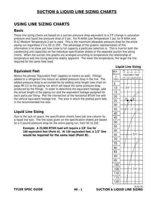
<strong>SUCTION</strong> & <strong>LIQUID</strong> <strong>LINE</strong> <strong>SIZING</strong> <strong>CHARTS</strong><br />
<strong>USING</strong> <strong>LINE</strong> <strong>SIZING</strong> <strong>CHARTS</strong><br />
Basis<br />
These line sizing charts are based on a suction pressure drop equivalent to a 2°F change in saturation<br />
pressure and liquid line pressure drop of 5 psi. For R-404A Low Temperature 1 psi; for R-404A and<br />
R-22 Medium Temperature 2 psi is used. This is the maximum allowable pressure drop for the entire<br />
piping run regardless if it is 50' or 250'. The advantage of the graphic representation of this<br />
information is to show just how close to full capacity a particular selection is. This is true for both the<br />
condensing unit capacities on the individual specification sheets or the separate suction line sizing<br />
charts. When the suction line graphs are arranged according to temperature the relationship of<br />
temperature and line sizing become readily apparent. The lower the temperature, the larger the line<br />
required for the same heat load.<br />
Equivalent Feet<br />
Notice the phrase "Equivalent Feet" (applies to meters as well). Fittings<br />
added to a refrigerant line induce an added pressure drop in the line. The<br />
added pressure drop is accounted for by adding extra length (see chart on<br />
page MI-11) to the piping run which will equal the same pressure drop<br />
produced by the fittings. In order to determine the equivalent footage, add<br />
the actual length of the piping run and the equivalent footage assigned for<br />
each particular fitting. Plot the intersection of the horizontal BTUH line with<br />
the vertical equivalent footage line. The area in which the plotted point falls<br />
in the recommended line size.<br />
Liquid Line Sizing<br />
Liquid Line Sizing<br />
Due to the lack of space, the specification sheets have just one column for<br />
a liquid line size. The line sizes given on the specification sheets are based<br />
on a 5 pound pressure drop for the entire piping run, from 50' to 250'.<br />
Example: A 25,000 BTUH load will require a 3/8" line for<br />
100 equivalent feet (Point A). At 150 equivalent feet, a 1/2" line<br />
would be required for the same load (Point B).<br />
TYLER SPEC GUIDE<br />
MI - 1<br />
26-Apr-06<br />
<strong>SUCTION</strong> & <strong>LIQUID</strong> <strong>LINE</strong> <strong>SIZING</strong>
Sizing Suction & Liquid Sub-Feed Line Properly<br />
NOTE: Liquid & suction line lengths over 300 equivalent feet are discouraged by TYLER.<br />
Contact Applications Engineering for recommendations exceeding 300 equivalent feet!<br />
CASE-TO-CASE <strong>SUCTION</strong> <strong>LINE</strong> SUB-FEED BRANCH <strong>LINE</strong> <strong>SIZING</strong><br />
FT 6 8 12 16 20 24 28 32 36 40 44 48 52 56<br />
R-404A 1/2” 7/8” 7/8” 7/8” 7/8” 1-1/8” 1-1/8” 1-1/8” 1-1/8” 1-1/8” 1-1/8” 1-1/8” 1-1/8” 1-1/8”<br />
Suction Line Sizing<br />
The line sizing charts on each case specification sheet can be used to size the subfeed branch lines.<br />
When the line serves one case. select the size specified for 50 equivalent feet for the 8’<br />
or 12’ case. This may be as small as 5/8” (example service meat cases), or as large as 1-3/8” (example<br />
multi-shelf ice cream cases). Select each suceeding step on the basis of the number of feet of case<br />
being served by that portion of the suction line.<br />
Liquid Line Sizing<br />
Use the liquid line size chart on page MI-10 to determine the appropriate size in the same manner as for<br />
suction lines.<br />
Exception - In the case of gas defrost, follow the special instructions on page MI-6 making and<br />
sizing a liquid line manifold at the case.<br />
Low temp suction lines and all liquid lines must be insulated in all Nature’s Cooling and<br />
Enviroguard applications! Horizontal suction lines should slope 1/2” per 10’ toward the<br />
compressor to aid in good oil return.<br />
TYLER SPEC GUIDE<br />
MI - 2<br />
25-Apr-06<br />
<strong>SUCTION</strong> & <strong>LIQUID</strong> <strong>LINE</strong> <strong>SIZING</strong>
REFRIGERATION PIPING<br />
Successful Installation of a Refrigeration System is Dependent Upon:<br />
1. Good piping practices - with properly sized and installed lines as described in this section.<br />
2. Cleanliness of all refrigeration piping is of the utmost importance in the installation procedure.<br />
The use of gaseous nitrogen or carbon dioxide flowing at low pressure through the lines while they are<br />
being welded is necessary to assure relative freedom from oxides and scale which can clog the small<br />
ports on pilot operated valves and other valves in this system.<br />
Some Possible Consequences of Poor Piping:<br />
• Increased oil requirements.<br />
• Decreased operating efficiency and loss of capacity.<br />
• Increased chances of fouling vital components.<br />
• Failed compressors.<br />
When NC-2, NC-3 or Enviroguard is employed, ALL <strong>LIQUID</strong> <strong>LINE</strong>S to and from the parallel rack (all<br />
the way from the building entrance to the fixtures) MUST BE INSULATE! Allowing subcooled liquid to<br />
warm in the lines cancels the energy saving advantage of subcooling the liquid and may even cause<br />
liquid to “flash”. Flashing occurs when liquid converts to gas before reaching the expansion valve;<br />
this will cause erratic valve feed and subsequent loss of refrigeration.<br />
ALL LOW TEMP <strong>SUCTION</strong> <strong>LINE</strong>S MUST BE INSULATED in order to assure cool suction gas to the<br />
compressor. Cool gas is necessary to aid in cooling the motor windings (Head cooling fans help and<br />
sometimes are required by the compressor manufacturer). Compressor motor failure can result if the<br />
suction gas from fixtures warms too much on its way to the compressor.<br />
WITH GAS DEFROST, INSULATION ON THE <strong>SUCTION</strong> <strong>LINE</strong> helps maintain the temperature of the<br />
hot gas flowing to the cases during defrost.<br />
Insulation on suction and liquid lines helps make the whole system more efficient.<br />
Insulate - it pays!<br />
The purpose of this section is to stress some of the more important aspects of piping, and areas in<br />
which difficulties are most likely to occur. This information is general, and cannot allow for all the<br />
possible factors in a given installation which can accumulate to make it less than acceptable.<br />
Page MI-? on pressure drop emphasizes the importance of properly designing the piping system.<br />
Materials<br />
Use only clean, dry, sealed refrigeration grade copper tubing. Make copper to copper joints with<br />
phos-copper alloy or equal. Make joints of dissimilar metals of 35% silver solder. To prevent<br />
contamination of the line internally, limit the soldering paste or flux to the minimum required. Flux<br />
the male portion of the connection, never the female.<br />
TYLER SPEC GUIDE<br />
MI - 3<br />
26-Apr-06<br />
<strong>SUCTION</strong> & <strong>LIQUID</strong> <strong>LINE</strong> <strong>SIZING</strong>
Piping should be purged with dry nitrogen or carbon dioxide during the brazing process. This will prevent<br />
formation of copper oxide and scale inside the piping which can easily clog the small ports on pilot<br />
operated and other valves in the system.<br />
CAUTION<br />
Pressure regulators must be used with nitrogen or carbon dioxide.<br />
Service Valves<br />
Field installed ball type service valves ARE RECOMMENDED TO FACILITATE SERVICING between the<br />
machine rack, the remote condenser, and the heat recovery coil.<br />
Use long radius elbows rather than short radius elbows. Less pressure drop and greater strength<br />
make the long radius elbows better for the system. This is particularly important on discharge hot gas<br />
lines for strength, and suction lines for reduced pressure drop.<br />
Vibration Isolation and Piping Support<br />
Piping must be properly supported to minimize line vibration. Vibration is transmitted to the piping<br />
by movement of the compressor and pressure pulsations of the refrigerant as it is pushed through<br />
the piping.<br />
Insufficient and improper supporting of tubing can cause excessive line vibration<br />
resulting in:<br />
• Excessive noise.<br />
• Noise transmission to other parts of building.<br />
• Vibration transmission of floors, walls, etc.<br />
• Vibration transmission back to compressor and other attached components.<br />
• Decreased life of all attached components.<br />
• Line breakage.<br />
Guidelines For Good Piping<br />
1. A STRAIGHT RUN OF PIPING, must be supported at each end. Longer runs will require additional<br />
supports along the length; usually these are not more than 8’ intervals, depending on tubing size<br />
and situation. Clamps should be properly anchored and rubber grommets installed between the<br />
piping and clamp to prevent line chafing.<br />
TYLER SPEC GUIDE<br />
MI - 4<br />
25-Apr-06<br />
<strong>SUCTION</strong> & <strong>LIQUID</strong> <strong>LINE</strong> <strong>SIZING</strong>
Supporting Corners<br />
2. CORNERS MUST BE SUPPORTED and cannot be left free to pivot around the A-B axis as<br />
shown above.<br />
Don’t Overdo It!<br />
3. DON’T OVER SUPPORT PIPING when it is attached to the compressor rack. It must be free to<br />
float without stress.<br />
4. DON’T USE SHORT RADIUS ELBOWS: They can have excessive internal stress which can lead<br />
to failure.<br />
5. CHECK ALL PIPING AFTER THE SYSTEM HAS BEEN PLACED IN OPERATION: Excessive vibration<br />
must be corrected as soon as possible. Extra supports are cheap when compared to the potential<br />
refrigerant loss caused from failed piping.<br />
PROPER <strong>LINE</strong> <strong>SIZING</strong> IS THE RESPONSIBILITY OF THE INSTALLING CONTRACTOR! Applications<br />
Department recommendations are listed on the System Summary Sheet furnished (if requested) with<br />
the job. Also, refer to the line sizing charts in these instructions. Horizontal suction lines should<br />
slope 1/2” per 10’ toward the compressor to aid in good oil return!<br />
TYLER SPEC GUIDE<br />
MI - 5<br />
26-Apr-06<br />
<strong>SUCTION</strong> & <strong>LIQUID</strong> <strong>LINE</strong> <strong>SIZING</strong>
Gas Defrost Liquid Lines<br />
Branch Lines<br />
Liquid lines to the cases should be branched off the bottom of the header. This ensures a full coulmn<br />
of liquid to the expansion valve. A branch line from the header to an individual case should not be over<br />
3’ long and must have a 3” expansion loop incorporated.<br />
Don’t Cross Pipe Systems<br />
Do not run suction or liquid lines through cases that are part of a separate system, especially if either<br />
has gas defrost. If there is no way to avoid this, insulate the piping for the portion that runs through<br />
the other cases.<br />
Allow For Expansion<br />
The temperature variations of refrigeration and defrost cycles cause piping to expand and contract. The<br />
expansion of piping must be taken into consideration, otherwise a piping failure will result. The following<br />
are typical expansion rates for copper tubing:<br />
-40°F to -100°F = 2.5” per 100 feet of run (ultra low temp)<br />
0°F to -40°F = 2” per 100 feet of run (low temp)<br />
0°F to +40°F = 1.5” per 100 feet of run (medium temp)<br />
+30°F to +50°F = 1” per 100 feet of run (high temp)<br />
Expansion loops are designed to provide a definate amount of travel. Placing the loop in the middle<br />
of a piping run will allow for maximum pipe expansion with the minimal amount of stress on the loop.<br />
Don’t use 45 degree elbows for loop construction because they will not allow the lines to flex. Refer<br />
to the charts on the next page for expansion loop lengths. Suction and liquid lines cannot be joined<br />
together or be allowed to touch. Pipe hangers must not restrict the expansion and contraction of piping.<br />
Insulation on suction and liquid lines makes the whole system more efficient! Insulate - it pays!<br />
TYLER SPEC GUIDE<br />
MI - 6<br />
25-Apr-06<br />
<strong>SUCTION</strong> & <strong>LIQUID</strong> <strong>LINE</strong> <strong>SIZING</strong>
Expansion Loop Sizing<br />
Chart #1 is to be used for A, B and C type loops.<br />
Chart #2 gives the total length of the expansion joint (L) along the outer surface.<br />
Example: Given a 200 foot run of 1-3/8” medium temp piping; there will be a linear expansion of 3” to<br />
compensate for (medium temp 1.5” per 100 feet). Pipe diameter has no affect on the amount of linear<br />
expansion but is needed for determining the size of the expansion loop. Find the 3” column at the top of<br />
Chart #1 and go down until it crosses the 1-3/8” row. The X dimension is 24”. If using type A loop, it will<br />
be 24”; 48” for type B; and 72” for type C.<br />
Chart #1<br />
TUBE OD ‘X’ LENGTH - (IN INCHES) FOR <strong>LINE</strong>AR EXPANSION OF:<br />
1/2” 1” 1-1/2” 2” 2-1/2” 3” 4” 5” 6” 7”<br />
7/8” 8” 11” 13” 15” 17” 19” 22” 24” 27” 29”<br />
1-1/8” 9” 12” 15” 17” 20” 21” 25” 28” 30” 33”<br />
1-3/8” 10” 14” 17” 19” 22” 24” 27” 31” 34” 36”<br />
1-5/8” 10” 15” 18” 21” 24” 26” 30” 33” 37” 39”<br />
2-1/8” 12” 17” 21” 24” 27” 30” 34” 38” 42” 45”<br />
2-5/8” 13” 19” 23” 27” 30” 33” 38” 42” 46” 50”<br />
3-1/8” 15” 21” 25” 29” 33” 36” 41” 46” 51” 55”<br />
4-1/8” 17” 24” 29” 34” 38” 41” 48” 53” 58” 63”<br />
5-1/8” 19” 26” 32” 37” 42” 46” 53” 59” 65” 71”<br />
6-1/8” 20” 29” 35” 41” 46” 50” 58” 65” 71” 77”<br />
Chart #2<br />
TUBE OD ‘X’ LENGTH - (IN INCHES) FOR <strong>LINE</strong>AR EXPANSION OF:<br />
1/2” 1” 1-1/2” 2” 2-1/2” 3” 4” 5” 6” 7”<br />
7/8” 24” 34” 42” 49” 54” 60” 69” 77” 84” 91”<br />
1-1/8” 28” 39” 48” 55” 62” 68” 78” 87” 96” 104”<br />
1-3/8” 30” 43” 53” 61” 68” 75” 86” 97” 106” 114”<br />
1-5/8” 33” 47” 58” 66” 74” 81” 94” 105” 115” 124”<br />
2-1/8” 38” 54” 66” 76” 85” 93” 108” 120” 132” 142”<br />
2-5/8” 42” 60” 73” 85” 95” 104” 120” 134” 147” 158”<br />
3-1/8” 46” 65” 80” 92” 103” 113” 131” 146” 160” 173”<br />
4-1/8” 53” 75” 92” 106” 119” 130” 150” 168” 184” 198”<br />
5-1/8” 59” 84” 102” 118” 132” 147” 167” 187” 205” 224”<br />
6-1/8” 65” 91” 112” 129” 145” 158” 183” 204” 224” 242”<br />
TYLER SPEC GUIDE<br />
MI - 7<br />
26-Apr-06<br />
<strong>SUCTION</strong> & <strong>LIQUID</strong> <strong>LINE</strong> <strong>SIZING</strong>
Suction Line Riser Recommendations<br />
1. Risers which can be Installed without a Trap<br />
Suction line sizing is based on a design pressure drop which<br />
relates to the velocity of the gasses moving through the line.<br />
Acceptable velocities for horizontal suction lines (with proper<br />
1/2” slope per 10’ run) range from 500’ to more than 1500’<br />
per minute. A properly sized line at the low range of its<br />
capacity will have a low velocity and one at full capacity will<br />
have velocities exceeding 1500 fpm. A specified minimum<br />
velocity is required to keep oil moving along with the gas when<br />
the pipe is vertical. The charts on the next page shows the<br />
size selection which will assure oil return up a riser. This size<br />
may be the same as the horizontal suction line selection or it<br />
may be one size smaller. If the selection point on the chart is<br />
close to the dividing line between sizes, use the smaller size.<br />
The reducer fitting must be placed after the elbow. Long<br />
elbows can be used to make the trap, or a P-trap can be used.<br />
Do not use short elbows.<br />
2. Risers which Require a P-Trap<br />
Low temperature systems must be designed knowing that oil<br />
is more difficult to move as the temperature is lowered. The<br />
refrigerant gas also has a lower capacity to mix with the oil. A<br />
trap will allow oil to accumulate, reducing the cross section of<br />
the pipe and thereby increase the velocity of the gas. This<br />
increased velocity picks up the oil. The velocity chart is to be<br />
used to determine if the horizontal line size has sufficient<br />
velocity in the vertical position to carry the oil along. Generally,<br />
the riser will have to be reduced one size.<br />
3. Risers Requiring Use of Two Traps<br />
The use of two traps is necessary on long risers for the collection of oil during an off cycle. One<br />
trap would not be large enough to contain all coating a riser over 16’, and could result in an oil slug<br />
delivered to the compressor system.<br />
Supporting Lines: Properly supprting the lines suspended from a wall or ceiling is very<br />
important. Line supports should isolate the lines from contact with metal. When gas<br />
defrost is used, consideration should be given to rolling or sliding supports which allow<br />
free expansion and contraction. These supports would be used in conjunction with<br />
expansion loops described on page MI-7.<br />
MAXIMUM RECOMMENDED SPACING BETWEEN SUPPORTS FOR COPPER TUBING<br />
O.D. Line Size (In.) Max. Span (Ft.) O.D. Line Size (In.) Max. Span (Ft.)<br />
5/8” 5’ 3-1/8” 12’<br />
1-1/8” 7’ 3-5/8” 13’<br />
1-5/8” 9’ 4-1/8” 14’<br />
2-1/8” 10’ - - - - - -<br />
TYLER SPEC GUIDE<br />
MI - 8<br />
25-Apr-06<br />
<strong>SUCTION</strong> & <strong>LIQUID</strong> <strong>LINE</strong> <strong>SIZING</strong>
Vertical Riser Suction Line Size Charts<br />
Proper line sizing is very important. When sizing for a suction line riser, use the proper chart. These<br />
charts are based on maintaining minimum velocities in the risers. This will assure that the oil mixed<br />
with the refrigerant will return to the compressor. Improper line sizing could cause less than optimum<br />
performance or pose the possibility of compressor damage due to oil failure.<br />
Suction line sizing charts apply to horizontal runs only. DO NOT use them for sizing vertical runs.<br />
Liquid line sizing charts can be used for both horizontal and vertical runs.<br />
CAUTION<br />
When in doubt about oil return (due to a point being near a line), use the smaller size line.<br />
Any sizing of riser or any other suction line, or device, must be considered in view of the total system.<br />
The addition of any suction line pressure drop must be ignored.<br />
If suction”P-traps” are used, it is recommended that they be sized according to the horizontal line sizing.<br />
IMPORTANT!<br />
Do not arbitrarily reduce vertical risers without consulting these charts. Unnecessary vertical<br />
suction line reduction can cause excessive pressure drop, resulting in loss of system capacity.<br />
R-22 R-404A<br />
TYLER SPEC GUIDE<br />
MI - 9<br />
26-Apr-06<br />
<strong>SUCTION</strong> & <strong>LIQUID</strong> <strong>LINE</strong> <strong>SIZING</strong>
Line Sizing Guidelines<br />
Minimum Horizontal Suction Velocity = one half of Minimum Riser Velocity.<br />
Maximum Pressure Drop<br />
R-22MT = 2.21 R-22LT = 1.15 R-404A = 2.46 R-404A = 1.33<br />
MINIMUM RISER VELOCITY<br />
R-22MT R-22LT R-404AMT R-404ALT<br />
1/2” 560 850 440 660<br />
5/8” 630 950 490 740<br />
7/8” 750 1130 590 890<br />
1-1/8” 860 1300 670 1010<br />
1-3/8” 960 1440 750 1120<br />
1-5/8” 1040 1570 810 1230<br />
2-1/8” 1200 1810 930 1410<br />
2-5/8” 1330 2010 1040 1570<br />
MINIMUM HORIZONTAL <strong>SUCTION</strong> VELOCITY<br />
R-22MT R-22LT R-404AMT R-404ALT<br />
1/2” 280 425 220 330<br />
5/8” 315 475 245 370<br />
7/8” 375 565 295 445<br />
1-1/8” 430 650 335 505<br />
1-3/8” 480 720 375 560<br />
1-5/8” 520 785 405 615<br />
2-1/8” 600 905 465 705<br />
2-5/8” 665 1005 520 785<br />
NOTE: Use R-404A information for R-504 & R-507<br />
R-22 & R-404A Liquid Line Sizing Chart<br />
TYLER SPEC GUIDE<br />
MI - 10<br />
25-Apr-06<br />
<strong>SUCTION</strong> & <strong>LIQUID</strong> <strong>LINE</strong> <strong>SIZING</strong>
<strong>USING</strong> <strong>SUCTION</strong> <strong>LINE</strong> <strong>SIZING</strong> <strong>CHARTS</strong> CORRECTLY<br />
Suction Line Sizing Charts<br />
The Suction Line Sizing charts include R-404A and R-22 suction temperatures, and lengths to 300<br />
equivalent feet.* These charts are based on DuPont data and extensive field experience. The<br />
advantage of the graph presentation of information is to show just how close to full capacity a<br />
particular selection is. The suction line graphs are arranged according to temperature, and the<br />
relationship of temperature and line size becomes readily apparent. The lower the temperature,<br />
the larger the line for the same heat load.<br />
*To determine the “Equivalent Feet” (or Meters), add the length<br />
of the pipe and the equivalent footage assigned for each particular<br />
fitting. See chart below.<br />
Find the Proper Chart<br />
Find the proper chart based on refrigerant and suction temp. Simply<br />
match BTUH load on the horizontal lines with equivalent feet on the<br />
vertical line. The point formed by the intersection will indicate the proper<br />
size unless it is a dark area. Selections falling inthe dark areas of the<br />
charts show that the gas velocity is too slow to assure proper oil return,<br />
even with properly sloped lines. Reducing the line one size will increase<br />
velocity and pressure drop. Added pressure drop will require greater<br />
refrigeration capacity. Be sure the system can handle the added load.<br />
See the vertical riser charts for proper sizing of vertical suction lines on<br />
page MI-10.<br />
Step Sizing<br />
Step sizing is suggested for selections falling in the first half of a size<br />
range. Pipe one size smaller (than the indicated run) can be used for 50’<br />
of the run closest to the cases when the entire run is 100 equivalent feet<br />
or more. To show this principle, one size range on each suction chart<br />
has been bisected by a dotted line to indicate the “First Half-Step Size”<br />
and the “2nd Half - Full Size”. The purpose of step sizing is to assure<br />
better oil return out of the evaporators.<br />
Example: Given a 50,000 BTUH load with R-404A at 10°F Suction<br />
Temp and 150 Equivalent ft. of line, a 1-5/8” line is required. Since<br />
the selection point is in the first half of the range 50’ equivalent feet<br />
may be sized 1-3/8” usually applied to the first 50’ closest to the evaporators, but any 1-3/8”<br />
vertical riser height should be subtracted from the 50’ step sizing.<br />
EQUIVALENT LENGTH OF PIPE FOR FITTINGS & VALVES (FEET)<br />
Line Size O.D. Global Valve Angle Valve 90° Elbow 45° Elbow Tee, Sight Glass T-Branch<br />
1/2 9 5 0.9 0.4 0.6 2.0<br />
5/8 12 6 1.0 0.5 0.8 2.5<br />
7/8 15 8 1.5 0.7 1.0 3.5<br />
1-1/8 22 12 1.8 0.9 1.5 4.5<br />
1-3/8 35 17 2.8 1.4 2.0 7.0<br />
2-1/8 45 22 3.9 1.8 3.0 10.0<br />
2-5/8 51 26 4.6 2.2 3.5 12.0<br />
3-1/8 65 34 5.5 2.7 4.5 15.0<br />
3-5/8 80 40 6.5 3.0 5.0 17.0<br />
TYLER SPEC GUIDE<br />
MI - 11<br />
26-Apr-06<br />
<strong>SUCTION</strong> & <strong>LIQUID</strong> <strong>LINE</strong> <strong>SIZING</strong>
R-22 Suction Line Sizing<br />
Step Sizing<br />
Step sizing is suggested for selection in the first half of a size range. Pipe ine size smaller can be<br />
used in the 50’ closest to the cases when the entire run is 100’ or more. Selections falling in the<br />
BLACK AREAS of the chart show that the gas velocity is below 750 fpm, which is too slow to assure<br />
proper oil return. Reducing one size will assure good oil return by increasing velocity, but the added<br />
pressure drop will require greater refrigeration capacity. Be sure the compressor selection is adequate.<br />
NOTE:<br />
All horizontal suction lines should be sloped 12” per 10’ toward the compressor.<br />
See vertical riser charts for proper vertical suction line sizing.<br />
TYLER SPEC GUIDE<br />
MI - 12<br />
25-Apr-06<br />
<strong>SUCTION</strong> & <strong>LIQUID</strong> <strong>LINE</strong> <strong>SIZING</strong>
R-404A Suction Line Sizing<br />
Step Sizing<br />
Step sizing is suggested for selection in the first half of a size range. Pipe ine size smaller can be<br />
used in the 50’ closest to the cases when the entire run is 100’ or more. Selections falling in the<br />
BLACK AREAS of the chart show that the gas velocity is below 500 fpm, which is too slow to assure<br />
proper oil return. Reducing one size will assure good oil return by increasing velocity, but the added<br />
pressure drop will require greater refrigeration capacity. Be sure the compressor selection is adequate.<br />
NOTE:<br />
All horizontal suction lines should be sloped 12” per 10’ toward the compressor.<br />
See vertical riser charts for proper vertical suction line sizing.<br />
TYLER SPEC GUIDE<br />
MI - 13<br />
26-Apr-06<br />
<strong>SUCTION</strong> & <strong>LIQUID</strong> <strong>LINE</strong> <strong>SIZING</strong>
Avoiding Excessive Pressure Drop<br />
Pressure drop and resultant capacity losses are becoming more common with the increased use or EPR<br />
valves, suction line filters, accumulators and suction manifolds on parallel systems. Each device stands<br />
on its own individual merit by contributing to case or system performance. But when all the resultant<br />
pressure drops are added, the end result is lower overall system performance. The symptoms may lead<br />
one to believe that the system is undersized, but a thorough check using a differential pressure gauge<br />
will very likely show where the real trouble lies.<br />
Some Pressure Drop Built In<br />
In general, most manufacturers rate their equipment by allowing for approximately two pounds pressure<br />
drop in the suction line between the evaporator to the compressor. Pressure drop built into the evaporator<br />
is usually considered by the designer and can frequently be larger than two pounds. This is to provide<br />
refrigerant velocities high enough to ensure good oil movement even in the coldest parts of the<br />
refrigeration system.<br />
Avoiding Excessive Loss of Capacity<br />
1. Size liquid and suction lines by accurately figuring the proper equivalent length.<br />
EQUIVALELNT LENGTH = ACTUAL PIPING + LENGTH EQUIVALENCE FOR FITTINGS<br />
AND COMPONENTS<br />
Use the equivalent length chart located on page MI-11 to determine the appropriate length<br />
for the fittings.<br />
2. If possible, avoid high pressure drop components, such as various types of control valves,<br />
manifolds, tees, accumulators and filters. These devices should only be used, after all the<br />
factors have been considered. The disadvantages must be outweighed by the advantages<br />
of combining systems, paralleling compressor, obtaining better case temperature control,<br />
protecting the compressors and/or safeguarding the system.<br />
3. If suction line filters are to be used, size them properly. Use a filter which is the same as<br />
main line size or one size over the suction service valve (whichever is larger).<br />
When Losses Are Not Made Up<br />
When pressure drop losses are not properly compensated for, an increase in case entering air<br />
temperature can be expected. This will be particularly noticeable when condensing unit is operating<br />
at its design ambient condition (90°F or 100°F).<br />
The following approximations can be made:<br />
Low Temp Case; each 10% increase (2# P.D.) raises entering air temp about 3°F.<br />
Medium Temp Case; each 10% increase raises entering air temp about 2°F.<br />
TYLER SPEC GUIDE<br />
MI - 14<br />
25-Apr-06<br />
<strong>SUCTION</strong> & <strong>LIQUID</strong> <strong>LINE</strong> <strong>SIZING</strong>
HIGH SIDE FIELD PIPING<br />
Observe piping run limits for best performance.<br />
• Maximum 50 equivalent piping feet to Remote Condenser.<br />
• Maximum 100 equivalent piping feet to Heat Recovery Coil.<br />
• Maximum 200 equivalent piping feet total for entire circuit.<br />
• Line size between remote condenser and Heat Recovery coil must be the same size<br />
as the discharge line.<br />
Installation Notice<br />
Remote condensers must be mounted enough in relation to the parallel rack so that the liquid drain<br />
on the condenser is at least 3’ higher that the liquid return inlet on the receiver. This is necessary to<br />
ensure free draining. The schematics below show which items need to be installed as field piping. All<br />
items above the broken line are considered part of the field piping and are shipped loose. A detailed<br />
description can be found in the “Parallel Compressor & Envoroguard Installation & Service Manual”.<br />
All the components shown in the field piping diagram should be installed. If a heat recovery coil is<br />
used, 3 check valves must be installed as shown in the diagram. One is placed in the normal flow<br />
piping to the condenser and the other two at the inlet and outlet of the HR coil. An optional IPR valve<br />
for the HR coil will also need to be field installed on the coil, for NC-2 only. Isolation ball valves are<br />
recommended for the system and can be ordered as optional equipment.<br />
Schematics Are Representative Only<br />
TYLER SPEC GUIDE<br />
MI - 15<br />
26-Apr-06<br />
<strong>SUCTION</strong> & <strong>LIQUID</strong> <strong>LINE</strong> <strong>SIZING</strong>
Discharge to Remote Condenser & Heat Recovery Line Sizing<br />
R-22 R-404A R-22 R-404A<br />
CAPACITY EQUIVALENT LENGTH CAPACITY EQUIVALENT LENGTH<br />
BTUH 50’ 100’ 50’ 100’ BTUH 50’ 100’ 50’ 100’<br />
6,000 3/8 1/2 1/2 1/2 75,000 7/8 1-1/8 1-1/8 1-1/8<br />
12,000 1/2 1/2 5/8 5/8 100,000 1-1/8 1-1/8 1-1/8 1-3/8<br />
18,000 5/8 5/8 5/8 7/8 150,000 1-1/8 1-3/8 1-3/8 1-3/8<br />
24,000 5/8 7/8 7/8 7/8 200,000 1-3/8 1-3/8 1-3/8 1-5/8<br />
36,000 7/8 7/8 7/8 7/8 300,000 1-3/8 1-5/8 1-5/8 2-1/8<br />
48,000 7/8 7/8 7/8 1-1/8 400,000 1-5/8 2-1/8 2-1/8 2-1/8<br />
60,000 7/8 1-1/8 1-1/8 1-1/8 500,000 2-1/8 2-1/8 2-1/8 2-1/8<br />
Recommended Liquid Line Sizing (Condenser to Receiver or Liquid Line Manifold)<br />
R-22 R-404A<br />
CAPACITY RECEIVER TO RECEIVER TO<br />
BTUH CONDENSER TO EVAPORATOR CONDENSER TO EVAPORATOR<br />
RECEIVER 50’ 100’ RECEIVER 50’ 100’<br />
6,000 3/8 1/4 3/8 3/8 1/4 3/8<br />
12,000 1/2 3/8 3/8 1/2 3/8 1/2<br />
18,000 1/2 3/8 3/8 5/8 1/2 1/2<br />
24,000 5/8 3/8 1/2 5/8 1/2 5/8<br />
36,000 5/8 1/2 1/2 7/8 1/2 5/8<br />
48,000 7/8 1/2 5/8 7/8 5/8 5/8<br />
60,000 7/8 1/2 5/8 7/8 5/8 7/8<br />
75,000 7/8 1/2 5/8 7/8 5/8 7/8<br />
100,000 7/8 5/8 7/8 1-1/8 7/8 7/8<br />
150,000 1-1/8 7/8 7/8 1-3/8 7/8 7/8<br />
200,000 1-1/8 7/8 7/8 1-3/8 1-1/8 1-1/8<br />
300,000 1-3/8 1-1/8 1-1/8 1-5/8 1-3/8 1-3/8<br />
400,000 1-5/8 1-1/8 1-1/8 1-5/8 1-3/8 1-3/8<br />
500,000 1-5/8 1-1/8 1-3/8 2-1/8 1-3/8 1-3/8<br />
TYLER SPEC GUIDE<br />
MI - 16<br />
25-Apr-06<br />
<strong>SUCTION</strong> & <strong>LIQUID</strong> <strong>LINE</strong> <strong>SIZING</strong>
Piping Procedures for Air Cooled Condensers<br />
When installing the condenser thermal expansion , it can be compensated for by an inverted piping<br />
configuration as shown in Figure 1 on page MI-18. This arrangement will act as an expansion loop<br />
for the pipe. All piping should also be run at various offset angles to help compensate for thermal<br />
expansion, (see View A).<br />
Figure 1 shows a view of a desirable inlet piping configuration. The<br />
piping out of the roof chase (if used) should angle from a vertical to a<br />
horizontal. This horizontal run should be supported from below. (All<br />
pipes must be individually clamped to the support to help minimize<br />
vibration). The piping should then angle upwrds at 90 degrees. This<br />
section of piping should also be supported to minimize longitudinal<br />
vibrations.<br />
From this point the piping will be redirected in the horizontal direction<br />
once again. This horizontal run should use offset piping to where it<br />
will need to be attached to the condenser. The 90 degree downward<br />
redirection completes the inverted piping configuration.<br />
In all cases try to minimize the “X” and “L” dimensions in your piping<br />
runs. In the case of “X”; the longer the unsupported horizontal length,<br />
the greater the likelihood of static stresses and vibration being placed<br />
on the condenser tube sheet.<br />
Outlet piping does not require the inverted configuration, but should<br />
otherwise be braced and supported in the same manner as stated<br />
above.<br />
Vibration Isolation & Piping Support<br />
Piping must be properly supported to minimize line vibration. Vibration is transmitted to the piping<br />
by movement of the compressor and pressure pulsations of the refrigerant as it is pushed through<br />
the piping. Insufficient and improper supporting of tubing can cause excessive line vibration resulting in:<br />
• Excessive noise.<br />
• Noise transmission to other parts of building.<br />
• Vibration transmission of floors, walls, etc.<br />
• Decreased life of all attached components.<br />
• Line breakage.<br />
A straight run of piping must be supported at each end. Longer runs require additional supports along<br />
the length, (usually not more than 8 foot intervals) depending on tubing size and situation. Clamps<br />
should be properly anchored and rubber grommets installed between the piping and clamp to prevent<br />
line clafing.<br />
NOTE<br />
A platform should be placed over any piping, to or from the condenser, that is likely to be<br />
stepped on. Most probable spots for this would be near the condenser shell or roof hatch.<br />
TYLER SPEC GUIDE<br />
MI - 17<br />
26-Apr-06<br />
<strong>SUCTION</strong> & <strong>LIQUID</strong> <strong>LINE</strong> <strong>SIZING</strong>
Materials<br />
Use only clean, dry, selaed refrigeration grade copper tubing. Make copper to copper joints with<br />
phos-copper alloy or equal. Make joints of dissimilar metals of 35% silver solder. To prevent<br />
contamination of the line internally, limit the soldering paste or flux to the minimum required. Flux<br />
only the male portion of the connection, never the female portion.<br />
Piping should be purged with dry nitrogen or carbon dioxide during the brazing process. This<br />
prevents formation of copper oxide and scale inside the piping which can easily clog the small<br />
ports on pilot operated and other valves in the system.<br />
Service Valves<br />
CAUTION<br />
Pressure regulators must always be used with nitrogen or carbon dioxide.<br />
Field installed ball type service valves are recommended to facilitate servicing between the<br />
machine rack, the remote condenser and the heat recovery coil.<br />
Use long radius elbows rather than short elbows. Less pressure drop and greater trength make<br />
the long radius elbows better for the system.<br />
Thermal Expansion<br />
Thermal expansion and construction cause piping systems to move. When installing piping to a<br />
condenser, this movement must be compensated for to prevent damage to the installed equipment.<br />
This motion can be accommodated by using the natural flexibility of the piping system during layout,<br />
by designing expansion loops, using expansion joints or the employment of fittings. The method<br />
selected depends on space, cost, serviceability and maintenance requirements.<br />
Thermal expansion and construction should be provided for by the use of piping bends, elbows,<br />
offsets or changes in direction of the piping run.<br />
TYLER SPEC GUIDE<br />
MI - 18<br />
25-Apr-06<br />
<strong>SUCTION</strong> & <strong>LIQUID</strong> <strong>LINE</strong> <strong>SIZING</strong>
RECOMMENDED CASE TEMPERATURE & DEFROST CONTROL SETTINGS<br />
Disch. Defrost Htr. EPR Defrost Control<br />
Case / Models Air Amps Settings Per Day, Fail-safe, Term. Temp.<br />
Alpine/Advantage/Alegro Temp. 6’ 8’ 12’ R-22 R-404A Electric Time Off Gas<br />
LF5 -28° 4.5 1 --- --- 6 12 2 @ 36/50° ----- 2 @ 15/55°<br />
NCSX, NCSGX -25° --- 13.8 20.6 3 8 1 @ 36/50° ----- 1 @ 25-30/55°<br />
NCN(G)X, NCBX (2) -25° --- 13.8 20.6 3 8 1 @ 36/50° ----- 1 @ 25-30/55°<br />
NCEX -25° 8.6 --- --- 3 8 1 @ 36/50° ----- 1 @ 25-30/55°<br />
NCJCX, NCJGCX -25° --- 21.6 34.6 3 8 1 @ 36/50° ----- 1 @ 25-30/55°<br />
NCJECX, NCJGECX -25° 7.8 --- --- 3 8 1 @ 36/50° ----- 1 @ 25-30/55°<br />
NTJCX, NTJGCX -25°/ --- 21.6 34.6 3/ 8/ 1 @ 36/50°/ ----- 1 @ 25-30/55°/<br />
(DUAL TEMP) -15° 7 14 1 @ 60/50° ----- 2-3 @ 20-25/55°<br />
NCWX -25° --- 13.8 20.6 3 8 1 @ 46/50° ----- 1 @ 25-30/55°<br />
LF5 -20° 4.5 1 --- --- 10 17 2 @ 36/50° ----- 2 @ 15/55°<br />
LFSC5 -19° 8.7 1 --- --- --- --- ----- 2 @ 36 -----<br />
NMF, NMFG -15° 6.5 6.9 10.3 7 14 1 @ 60/50° ----- 2 @ 16-20/55°<br />
NFX, NFSX, NFSGX -15° --- 6.9 10.3 7 14 1 @ 60/50° ----- 2-3 @ 20-25/55°<br />
NFN(G)X, NFB(G)X (2) -15° --- 6.6 10.3 7 14 1 @ 60/50° ----- 2-3 @ 20-25/55°<br />
NFEX, NFEGX -15° 8.6 --- --- 7 14 1 @ 60/50° ----- 2-3 @ 20-25/55°<br />
NFJCX, NFJGCX -15° --- 13.8 20.6 7 14 1 @ 60/50° ----- 2-3 @ 20-25/55°<br />
NFJECX, NFJGECX -15° 7.8 --- --- 7 14 1 @ 60/50° ----- 2-3 @ 20-25/55°<br />
NFMJCX, NFMJGCX -15°/ --- 13.8 20.6 7/ 14/ 1 @ 60/50°/ ----- 2-3 @ 20-25/55°/<br />
(DUAL TEMP) +22° 37 50 1 @ 36/50° ----- 2-3 @ 16-20/55°<br />
NFWX, NFWGX -15° --- 13.8 20.6 7 14 1 @ 46/50° ----- 2-3 @ 20-25/55°<br />
NFWEX -15° 6.9 --- --- 7 14 1 @ 46/50° ----- 2-3 @ 20-25/55°<br />
N6F, N6FL -10° 19.5 26.0 41.8 10 17 2-3 @ 40/55° ----- 3-4 @ 22-25/60°<br />
P5FG, P5FGN<br />
(101/E2 with HEAT) -8° 5.8 2 9.5 3 16.8 4 19 27 1 @ 46/60° ----- 1 @ 20-25/55°<br />
(ELIMINAATOR) -8° 5.8 2 9.5 3 16.8 4 12 19 1 @ 46/60° ----- 1 @ 20-25/55°<br />
NFL -5° 6.5 6.9 10.3 13 21 1 @ 46/50° ----- 2 @ 17-20/55°<br />
P5FG, P5FGN<br />
(101/E2 with HEAT) +1° 5.8 2 9.5 3 16.8 4 18 26 1 @ 46/60° ----- 1 @ 18-20/55°<br />
(ELIMINAATOR) +1° 5.8 2 9.5 3 16.8 4 17 25.5 1 @ 46/60° ----- 1 @ 18-20/55°<br />
NMW +18° 12.9 13.8 20.6 33 44 4 @ 40/50° 4 @ 40 4 @ 20/55°<br />
NMWE +18° 17.2 5 18.1 5 24.9 5 33 44 4 @ 40/50° 4 @ 40 4 @ 20/55°<br />
NMWEE +18° 21.5 6 22.4 6 29.2 6 33 44 4 @ 40/50° 4 @ 40 4 @ 20/55°<br />
LN5 +20° 4.3 1 --- --- 43 56 2 @ 30/50° ----- 2 @ 15/55°<br />
LNSC5 +20° 7.5 1 --- --- 43 56 ----- 2 @ 30 -----<br />
NFX, NFSX, NFSGX +22° --- 6.9 10.3 37 49.5 1 @ 36/50° ----- 2-3 @ 16-20/55°<br />
NFN(G)X, NFB(G)X (2) +22° --- 6.6 10.3 38 50 1 @ 36/50° ----- 2-3 @ 16-20/55°<br />
NFEX, NFEGX +22° 8.6 --- --- 38 50 1 @ 36/50° ----- 2-3 @ 16-20/55°<br />
NFJCX, NFJGCX +22° --- 13.8 20.6 37 50 1 @ 36/50° ----- 2-3 @ 16-20/55°<br />
NFJECX, NFJGECX +22° 7.8 --- --- 37 50 1 @ 36/50° ----- 2-3 @ 16-20/55°<br />
NFWX, NFWGX +22° --- 13.8 20.6 38 50 1 @ 36/50° ----- 2-3 @ 16-20/55°<br />
NFWEX +22° 6.9 --- --- 38 50 1 @ 36/50° ----- 2-3 @ 16-20/55°<br />
TYLER SPEC GUIDE<br />
MI - 19<br />
26-Apr-06<br />
<strong>SUCTION</strong> & <strong>LIQUID</strong> <strong>LINE</strong> <strong>SIZING</strong>
Disch. Defrost Htr. EPR Defrost Control<br />
Case / Models Air Amps Settings Per Day, Fail-safe, Term. Temp.<br />
NSF Advantage/Alegro Temp. 6’ 8’ 12’ R-22 R-404A Electric Time Off Gas<br />
N3MGE +23° 4.9 --- --- 38 50 6 @ 36/50° 6 @ 28 6 @ 12-15/55°<br />
LPFMT (Self-Serve) +23° --- --- --- 38 50 ----- 4 @ 40 -----<br />
LPFDT (Self-Serve) +23° --- --- --- 38 50 ----- 4 @ 40 -----<br />
LPFDT (Dome) +24° --- --- --- 38 50 ----- 4 @ 40 -----<br />
N6F, N6FL (Meat) +24° 19.5 26.0 41.8 38 50 2 @ 40/55° ----- 4 @ 12-15/60°<br />
N2PSE (Bulk) +24° 4.9 --- --- 43 56 ----- 6 @ 28 -----<br />
N2PSE (Meat/Deli) +24° 4.9 --- --- 38 49 6 @ 36/50° 6 @ 28 6 @ 12-15/55°<br />
NNG, TNG (Deli) +25° --- --- --- 38 50 ----- 6 @ 28 -----<br />
N3MG, N3HM, N3HMG +27° 6.5 6.9 10.3 38 50 6 @ 36/50° 6 @ 28 6 @ 12-15/55°<br />
N3HME, N3HMGE +27° 4.9 --- --- 38 50 ----- 6 @ 26 -----<br />
NSSD +27° 6.5 6.9 10.3 37 49 6 @ 36/50° 6 @ 28 6 @ 12-15/55°<br />
NMHP, NMGHP +27.5° --- --- --- 49 7 62 7 ----- 4 @ 44 -----<br />
NM, NMG +28° 6.5 6.9 10.3 38 50 4 @ 19/50° 4 @ 34 4 @ 12-15/55°<br />
NHMGHP +28° --- --- --- 49 7 62 7 ----- 4 @ 44 4 @ 15/45°<br />
N2MHP, N6MHP +28° --- --- --- 48 7 61 7 ----- 6 @ 26 -----<br />
N3HMHP, N3HMGHP +28° --- --- --- 49 7 62 7 ----- 6 @ 28 -----<br />
N4MHP, N4MGHP +28° --- --- --- 49 7 62 7 ----- 6 @ 28 -----<br />
N5MG +28° --- 6.9 10.3 38 50 6 @ 36/50° 6 @ 32 6 @ 12-15/55°<br />
N2PS (Bulk) +28° 6.5 6.9 10.3 43 56 ----- 6 @ 28 -----<br />
N2PS (Meat/Deli) +28° 6.5 6.9 10.3 38 49 6 @ 36/50° 6 @ 28 6 @ 12-15/55°<br />
NNG, TNG (Cheese) +28° --- --- --- 43 56 ----- 6 @ 28 -----<br />
LDRL +28° --- --- --- 37 49 ----- 4 @ 45 -----<br />
LPD (Pizza) +28° --- --- --- 38 50 ----- 4 @ 30 -----<br />
RCCG (Riser Opt. 2) +28° --- --- --- 35 46 ----- 4 @ 30 -----<br />
RCCG (Std. Riser) +28° --- --- --- 38 50 ----- 4 @ 30 -----<br />
(Riser Opt. 1)<br />
LDSSI +28.5° --- --- --- 44 57 ----- 4 @ 40 -----<br />
N3MGHP, N3MGHPE, +29° --- --- --- 49 7 62 7 ----- 4 @ 32 -----<br />
N3MGHPEX<br />
N5MHP, N5MGHP +29° --- --- --- 49 7 62 7 ----- 6 @ 26 -----<br />
LPFMT (Dome) +29° --- --- --- 38 50 ----- 4 @ 40 -----<br />
N2P (Meat/Deli) +30° 6.5 6.9 10.3 38 49 6 @ 36/50° 6 @ 28 6 @ 12-15/55°<br />
NLD, NFD, NVD +30° --- --- --- 36 47 ----- 1 @ 46 -----<br />
TLD, TLD(2, 4, 6) (L/R) +30° --- --- --- 52 67 ----- 4 @ 20 -----<br />
N6DHP(LR/MR) +31° --- --- --- 52 7 66 7 ----- 6 @ 16 -----<br />
NHDHP(L/M) (Shelving) +31° --- --- --- 52 7 66 7 ----- 6 @ 24 -----<br />
(Peg Bars/Mixed) +31° --- --- --- 50 7 64 7 ----- 6 @ 26 -----<br />
(Produce Insert) +31° --- --- --- 55 7 70 7 ----- 6 @ 24 -----<br />
N6D(LR/MR) +32° --- 6.9 10.3 44 57 4 @ 24/41° 4 @ 24 4 @ 15/55°<br />
NHD(L/M) +32° 4.7 6.9 10.3 44 57 4 @ 24/41° 4 @ 24 4 @ 15/55°<br />
LDFL +32° --- --- --- 43 56 ----- 4 @ 45 -----<br />
LD-48 +32° --- --- --- 41 53 ----- 6 @ 20 -----<br />
N2P (Bulk) +33° 6.5 6.9 10.3 43 56 ----- 6 @ 28 -----<br />
TYLER SPEC GUIDE<br />
MI - 20<br />
25-Apr-06<br />
<strong>SUCTION</strong> & <strong>LIQUID</strong> <strong>LINE</strong> <strong>SIZING</strong>
Disch. Defrost Htr. EPR Defrost Control<br />
Case / Models Air Amps Settings Per Day, Fail-safe, Term. Temp.<br />
NSF Advantage/Alegro Temp. 6’ 8’ 12’ R-22 R-404A Electric Time Off Gas<br />
N6D(L/M/H) +33° 4.7 6.9 10.3 44 57 4 @ 24/41° 4 @ 24 4 @ 15/55°<br />
N6PHPM26 (Bulk) +33° --- --- --- 54 7 68 7 ----- 6 @ 12 -----<br />
LD-54 +33° --- --- --- 41 53 ----- 6 @ 20 -----<br />
NP (Bulk) +34° --- --- --- 43 56 ----- 3-4 @ 40 -----<br />
P5NG, P5NGN +34° --- --- --- 51 65 ----- 1 @ 34 -----<br />
N6DN(L/M/H) +34° 4.7 6.9 10.3 44 57 6 @ 18/41° 6 @ 18 6 @ 15/55°<br />
N6DHP(L/M/H) (Shelving) +34° --- --- --- 52 7 66 7 ----- 6 @ 16 -----<br />
(Peg Bars/Mixed) +34° --- --- --- 50 7 64 7 ----- 6 @ 18 -----<br />
(Produce Insert) +36° --- --- --- 55 7 70 7 ----- 6 @ 16 -----<br />
TLM, TLF +34° --- --- --- 37 49 ----- 2 @ 70 -----<br />
TLM(2/4/6) (L/R) +34° --- --- --- 37 49 ----- 2 @ 70 -----<br />
LD-60 +34° --- --- --- 41 53 ----- 6 @ 20 -----<br />
LRPHP +34° --- --- --- 50 7 64 7 ----- 6 @ 12 -----<br />
N6F, N6FL (Dairy) +35° 19.5 26.0 41.8 49 62 2 @ 40/55° ----- 4 @ 12-15/60°<br />
N5P (Bulk) +35° --- --- --- 43 56 ----- 3 @ 40 -----<br />
NPW, NPWE, NPWEE, +35° --- --- --- 43 56 ----- 1 @ 60 -----<br />
NPE (Bulk)<br />
N5D, N5DH, N5DL +35° --- --- --- 37 49 ----- 4 @ 24 -----<br />
N5DSC +35° --- --- --- --- --- ----- 6 @ 28 -----<br />
LD-72 +35° --- --- --- 41 53 ----- 6 @ 20 -----<br />
N2PSSC (Bulk) +35° --- --- --- --- --- ----- 4 @ 18 -----<br />
NRPIE, NRPIEE +35° --- --- --- 43 56 ----- 1 @ 60 -----<br />
NLBR +36° --- --- --- 51 65 ----- 6 @ 20 -----<br />
NLBS +36° --- --- --- --- --- ----- 6 @ 20 -----<br />
FDESC (Floral) +37° --- --- --- --- --- ----- 6 @ 25 -----<br />
N1P, N4P (Bulk) +38° --- --- --- 43 56 ----- 3-4 @ 40 -----<br />
N3P(L/H) (Bulk) +38° --- --- --- 43 56 ----- 3 @ 40 -----<br />
N4PHP (Bulk) +39° --- --- --- 60 7 75 7 ----- 2 @ 10 -----<br />
N1PHP (Bulk) +42° --- --- --- 60 7 75 7 ----- 2 @ 10 -----<br />
NLM, NLF, NFM, NFF, N/A 8 --- --- --- 36 47 ----- 1 @ 110 -----<br />
NVM, NVF<br />
NOTES: 1) Defrost Heater Amps based on 5-foot case. 5) Defrost Heater Amps based on case with 1 end case.<br />
2) Defrost Heater Amps based on 2-door case. 6) Defrost Heater Amps based on case with 2 end cases.<br />
3) Defrost Heater Amps based on 3-door case. 7) ADD 0.5# to EPR setting for each 1000 foot rise in elevation.<br />
4) Defrost Heater Amps based on 5-door case. 8) N/A = Not Available.<br />
TYLER SPEC GUIDE<br />
MI - 21<br />
26-Apr-06<br />
<strong>SUCTION</strong> & <strong>LIQUID</strong> <strong>LINE</strong> <strong>SIZING</strong>
SUGGESTED TEMPERATURE CONTROLLING FOR CASES & WALK-IN COOLERS*:<br />
Electric Defrost<br />
For Parallel systems with Electric Defrost, the following controls are suggested for temperature control and defrost:<br />
1. All walk-in coolers should have a thermostat control wired to a liquid solenoid. The defrost solenoids for each<br />
circuit will be wired to a defrost timer.<br />
2. All medium temperature cases will have an EPR valve with a solenoid mounted at the rack for defrost. The<br />
defrost solenoids for each circuit will be wired to a defrost timer.<br />
3. All low temperature walk-in coolers and cases will have suction stop EPR valves mounted on the rack. No<br />
defrost solenoids are required because the defrost timer will be wired to the suction stop EPR valve.<br />
Gas Defrost<br />
For Parallel systems with Gas Defrost, the following controls are suggested for temperature control and defrost:<br />
1. Walk-in coolers with gas defrost will be controled by suction stop EPR valves.<br />
2. All medium temperature cases with gas defrost will be controlled wi a suction stop EPR valve.<br />
3. All low temperature walk-in coolers and cases with gas defrost will be controlled with a suction stop EPR valve.<br />
*Cases and walk-in coolers connected to an Enviroguard system should be set to the temperature and defrost<br />
control settings listed in the Enviroguard Installation & Service Manual.<br />
TYLER SPEC GUIDE<br />
MI - 22<br />
25-Apr-06<br />
<strong>SUCTION</strong> & <strong>LIQUID</strong> <strong>LINE</strong> <strong>SIZING</strong>