You also want an ePaper? Increase the reach of your titles
YUMPU automatically turns print PDFs into web optimized ePapers that Google loves.
Product Information Sheet<br />
810-3048 Light Dimming Module<br />
Part #: <strong>026</strong>-<strong>4215</strong> <strong>Rev</strong> 2 Date: 01/10/2008<br />
Overview<br />
The CPC Light Dimming Module is used to control<br />
light dimming ballast(s). The module is approximately<br />
3” x 5”. The module uses a single 0-10V DC analog<br />
output from a MultiFlex board. The input and output<br />
voltages are listed below.<br />
Board Input<br />
(MultiFlex)<br />
Board Output<br />
(Light Ballast)<br />
Light Condition<br />
0V DC 10V DC Full On<br />
10V DC 0V DC Min. On<br />
The module has a proof output. The proof output is connected to a NC relay output. If proofing is used,<br />
the output should be connected to any available analog input on a MultiFlex board. The dip switch for the<br />
analog input should be ON.<br />
Installation<br />
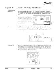
The Light Dimming Module can be installed in any orientation. The module includes a Snap-Track. The<br />
Snap-Track should be mounted in a standard enclosure. The module requires 12VAC. Connecting the<br />
power input to the AC1 and AC2 side of a standard 24V transformer will damage the module. A<br />
center-tap 24V transformer should be used to power the module as shown in the wiring diagram.<br />
250-2150 ISOLATOR<br />
(OPTIONAL)<br />
LIGHT BALLAST<br />
NOTE: REFER TO BALLAST WIRING<br />
DIAGRAM FOR FURTHER DETAILS.<br />
MULTIFLEX 168A0<br />
CPC DIMMING MODULE<br />
TYPICAL LIGHT DIMMING MODULE WIRING DIAGRAM<br />
Page 1 of 4 Computer Process Controls • 1640 Airport Road Kennesaw, GA 30144<br />
800-829-2724 • http://www.cpcus.com<br />
Visit http://www.emersonretailsolutions.com/library for the latest technical documentation.<br />
© 2006 Computer Process Controls, Inc. All rights reserved.
Product Information Sheet<br />
810-3048 Light Dimming Module<br />
Part #: <strong>026</strong>-<strong>4215</strong> <strong>Rev</strong> 2 Date: 01/10/2008<br />
Programming<br />
• The Light Dimming Module is configured in a Lighting Control application.<br />
• The E2 software must be 2.40F01 or later.<br />
• A light level sensor is required to control the light dimming.<br />
Program the Lighting Application normally. Then, make the following additional programming<br />
changes:<br />
1. Press and Log in to the E2 with Level 4 access<br />
2. Press view the Lighting Summary screen. If a list of Lighting Control applications appears,<br />
highlight the one you wish to edit and press to view the C1:Setup screen.<br />
3. If proofing is desired, change the Enable Proofing field to Yes.<br />
Change Enable Dimming field to Yes.<br />
Page 2 of 4 Computer Process Controls • 1640 Airport Road Kennesaw, GA 30144<br />
800-829-2724 • http://www.cpcus.com<br />
Visit http://www.emersonretailsolutions.com/library for the latest technical documentation.<br />
© 2006 Computer Process Controls, Inc. All rights reserved.
Product Information Sheet<br />
810-3048 Light Dimming Module<br />
Part #: <strong>026</strong>-<strong>4215</strong> <strong>Rev</strong> 2 Date: 01/10/2008<br />
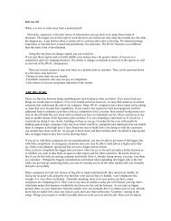
4. Press to view the C2: Light Level screen.<br />
5. Set the values circled in Red below based on the desired lighting operation.<br />
Dim Upper %: Light output percent at Dim LL @ Upper % light level<br />
Dim LL @ Upper %: Light level for Dim Upper % output<br />
Dim Lower %: Light output percent at Dim LL @ Lower % light level<br />
Dim LL @ Lower %: Light level for Dim Lower % output<br />
Dim Ramp Speed: Ramp speed in percent change per minute.<br />
Dim fail %: Light level output if light level sensor fails.<br />
6. Press + to view the C9: Outputs screen.<br />
7. Assign the Dimmer % output to the MultiFlex Analog Output connected to the dimmer module.<br />
Typically lighting gateway<br />
board or physical relay output<br />
Set Analog Output scaling to<br />
0.1V – 10.0V<br />
Page 3 of 4 Computer Process Controls • 1640 Airport Road Kennesaw, GA 30144<br />
800-829-2724 • http://www.cpcus.com<br />
Visit http://www.emersonretailsolutions.com/library for the latest technical documentation.<br />
© 2006 Computer Process Controls, Inc. All rights reserved.
Product Information Sheet<br />
810-3048 Light Dimming Module<br />
Part #: <strong>026</strong>-<strong>4215</strong> <strong>Rev</strong> 2 Date: 01/10/2008<br />
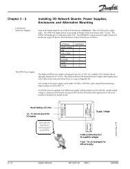
8. Press to view the C0: More screen.<br />
9. Change the Proof Type to ON Only<br />
10. Assign the Proof IN input to the MultiFlex Analog Input connected to the dimmer module.<br />
Typically lighting gateway<br />
board proof output<br />
Application Notes<br />
1. Typically the physical proof output from the 810-3048 Light Dimming Module is used as an alarm<br />
from a Digital Sensor Control application in the E2 controller. A delay of 5 minutes is<br />
recommended to minimize nuisance alarms.<br />
2. The optional 250-2150 isolator is needed when the control wires from the light dimming ballast are<br />
not isolated. If either side of the control wire circuit is intentionally or accidentally connected to<br />
ground, the 250-2150 isolator is required for the 810-3048 Light Dimming Module to function<br />
properly. The isolator separates the ground on the control wire from the CPC input board.<br />
Page 4 of 4 Computer Process Controls • 1640 Airport Road Kennesaw, GA 30144<br />
800-829-2724 • http://www.cpcus.com<br />
Visit http://www.emersonretailsolutions.com/library for the latest technical documentation.<br />
© 2006 Computer Process Controls, Inc. All rights reserved.