Power Supply Bypass Capacitor Selection and ... - NVE Corporation
Power Supply Bypass Capacitor Selection and ... - NVE Corporation
Power Supply Bypass Capacitor Selection and ... - NVE Corporation

You also want an ePaper? Increase the reach of your titles
YUMPU automatically turns print PDFs into web optimized ePapers that Google loves.
Application Bulletin AB-8<br />
<strong>Power</strong> <strong>Supply</strong> <strong>Bypass</strong> <strong>Capacitor</strong> <strong>Selection</strong><br />
<strong>Capacitor</strong> <strong>Selection</strong><br />
Most of the energy in digital pulses lies in the area below F knee , where:<br />
<strong>and</strong> t r is signal rise-time.<br />
For IsoLoop Isolators:<br />
F knee =<br />
0.5<br />
t r<br />
F knee =<br />
0.5<br />
= 167MHz<br />
3 x10 -9<br />
This frequency may be considered the analog “b<strong>and</strong>width” of the device.<br />
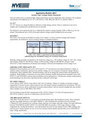
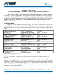
At higher frequencies (fast-rising edges), capacitors do not act as pure capacitors. <strong>Capacitor</strong>s have<br />
parasitic lead inductance <strong>and</strong> parasitic series resistance called equivalent series resistance (“ESR”). These<br />
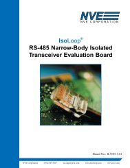
effects tend to reduce decoupling effectiveness at higher frequencies. A capacitor equivalent circuit is<br />
shown in Figure 1:<br />
R = dielectric losses.<br />
R ins<br />
L<br />
r<br />
R<br />
C<br />
R ins = insulation resistance.<br />
r = transfer resistance between<br />
electrodes <strong>and</strong> terminating wires.<br />
L = self inductance.<br />
Figure 1. Equivalent circuit of a capacitor at high frequency.<br />
<strong>Capacitor</strong> inductance is the component with the largest effect on ESR. A typical electrolytic capacitor<br />
has an inductance of around 10 nH – 20 nH, while a typical surface-mount ceramic capacitor has an<br />
inductance of around 500 pH. If we then look at the impedance of these capacitors, we can see the effect<br />
this inductance has on decoupling:<br />
For an electrolytic capacitor:<br />
Inductive Impedance = Z L<br />
Z L = 2 π f L<br />
= 2 x 3.142 x 1.67x10 8 x 20x10 -9<br />
= 21 Ω<br />
For a ceramic capacitor:<br />
Inductive Impedance = Z L<br />
Z L = 2 π f L<br />
= 2 x 3.142 x 1.67x10 8 x 500x10 -12<br />
= 0.5 Ω<br />
The peak current in IsoLoop parts is approximately 40 mA per channel. Ohm’s Law provides the<br />
instantaneous voltage drop at switching:<br />
<strong>NVE</strong> <strong>Corporation</strong> • 11409 Valley View Road, Eden Prairie, MN 55344-3617 • (952) 829-9217 • www.IsoLoop.com
Application Bulletin: AB-8<br />
Electrolytic capacitor<br />
V drop = I x Z L<br />
= (0.04 A) x (21 Ω)<br />
= 0.84 V<br />
Ceramic capacitor<br />
V drop = I x Z L<br />
= (0.04 A) x (0.5 Ω)<br />
= 0.02 V<br />
It is apparent from this example that if more than one channel switches at the same time, the supply<br />
voltage could drop below the minimum operating voltage of the device. Therefore it is extremely<br />
important to use the correct capacitor type. Always use ceramic capacitors. Use ceramic chip capacitors<br />
if possible since they have the lowest ESR. Polypropylene capacitors also have low ESRs, although they<br />
are more expensive.<br />
<strong>Capacitor</strong> Placement<br />
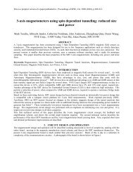
Decoupling capacitors as close as possible to the IsoLoop V dd pins minimizes the resistive <strong>and</strong><br />
inductive effects of printed circuit board traces, limiting the unwanted voltage drops discussed earlier.<br />
The importance of correct decoupling capacitor placement to ensure trouble-free operation cannot be<br />
overstressed. Arrows show correctly placed capacitors in Figure 2:<br />
Figure 2. Correct placement of decoupling capacitors.<br />
2<br />
ISB-AP-08; March 2007