You're Not Alone: Dealing with Isolation (.pdf) - NVE Corporation
You're Not Alone: Dealing with Isolation (.pdf) - NVE Corporation
You're Not Alone: Dealing with Isolation (.pdf) - NVE Corporation

Create successful ePaper yourself
Turn your PDF publications into a flip-book with our unique Google optimized e-Paper software.
You’re <strong>Not</strong> <strong>Alone</strong><br />
<strong>Dealing</strong> <strong>with</strong> <strong>Isolation</strong><br />
FROM THE<br />
BENCH<br />
Jeff Bachiochi<br />
directly for steady-state isolation. Opto<br />
devices work well in this scenario. An<br />
opto device does require a chunk of<br />
current to operate and the transfer<br />
ratio of input current to output current<br />
will usually require a trade-off of speed<br />
for drive current. This trade-off is not<br />
a problem until you want to transfer<br />
information at high speeds. Most opto<br />
devices have minimum T ON<br />
/T OFF<br />
times in the microsecond range.<br />
A new device in the isolation flurry<br />
takes a step back into the magnetic<br />
domain. <strong>NVE</strong> <strong>Corporation</strong> uses giant<br />
magneto resistive (GMR) sensors to<br />
transfer information using the magnetic<br />
fields produced by current in a<br />
conductor.<br />
Jeff hasn’t<br />
turned<br />
into a<br />
self-help<br />
writer, but<br />
you can help yourself<br />
by following along as<br />
he outlines the challenges<br />
and effects of<br />
isolation. Knowing<br />
what the options are<br />
will help keep your<br />
next project on track.<br />
w<br />
hen I think of<br />
isolation, I think<br />
of Robinson Crusoe<br />
and Friday or in more<br />
recent times, Tom Hanks as Chuck<br />
Noland. When I think isolation in the<br />
electronics context, I think of the<br />
transformer. For years, transformers<br />
have been used to isolate signals.<br />
Magnetic properties transfer information<br />
<strong>with</strong>out an electrical connection<br />
between primary and secondary windings.<br />
On most transformers, it’s the<br />
plastic bobbin that holds the primary<br />
and secondary windings separated that<br />
creates the isolation barrier. More<br />
recently, opto devices have become a<br />
popular method of obtaining isolation.<br />
As you can see in Figure 1, opto<br />
devices rely on light (or the absence of<br />
light) to transfer information between<br />
the physically separated primary (input)<br />
and secondary (output). Although the<br />
transformer is inherently a bidirectional<br />
isolation device, most isolation application<br />
requirements are unidirectional.<br />
LIGHTSOLATION<br />
Opto devices have the advantage of<br />
operating down to DC whereas transformers<br />
are specified at some AC bandwidth.<br />
From an isolated control point<br />
of view, transformers can’t be used<br />
MAGNESOLATION<br />
You may already be familiar <strong>with</strong><br />
Hall effect devices, which can be used<br />
to measure the strength of a magnetic<br />
field. The Hall effect is the presence of<br />
a voltage produced across (x-axis) a<br />
current-carrying conductor (y-axis) as a<br />
result of exposure to a magnetic field<br />
passing through the conductor (z-axis).<br />
This differs from the GMR effect.<br />
The GMR effect is a change in a<br />
thin film nonmagnetic conductive<br />
layer’s resistance caused by an external<br />
magnetic field overcoming the parallel<br />
but opposing magnetic coupling<br />
of adjacent magnetized layers (see<br />
Figure 2). You’ll remember that the<br />
spin of electrons in a magnet are<br />
aligned to produce a magnetic<br />
moment. Magnetic layers <strong>with</strong> opposing<br />
spins (magnetic moments) impede<br />
the progress of the electrons (higher<br />
scattering) through a sandwiched conductive<br />
layer. This arrangement causes<br />
the conductor to have a higher<br />
resistance to current flow.<br />
An external magnetic field can<br />
realign all of the layers into a single<br />
magnetic moment. When this happens,<br />
LED<br />
1″<br />
Signal transmitted<br />
by photo stream<br />
Galvanic isolation<br />
by bulk dielectric<br />
Photo detector<br />
V CC<br />
Isolated<br />
output<br />
A<br />
Figure 1—Optoisolators rely on physical separation<br />
between the LED transmitter and photo detector for isolation.<br />
Data is passed via photons (or the lack of).<br />
www.circuitcellar.com CIRCUIT CELLAR ® Issue 142 May 2002 1
a)<br />
b)<br />
High-resistance state<br />
+ + B + +<br />
A<br />
• • B • •<br />
Low-resistance state<br />
Magnetic<br />
moment<br />
orientation<br />
No external field<br />
+ + B + +<br />
A<br />
+ + B + +<br />
Applied external field<br />
Figure 2—In both a and b, the Alayers are the nonmagnetic<br />
conductive layer and the B layers are adjacent<br />
magnetic layers of opposing orientation. a—Layer<br />
Ais high resistance because of higher scattering of<br />
electrons flowing through it. b—An applied magnetic<br />
field realigns the magnetic moments in the B layers,<br />
resulting in a lower resistance in layer Abecause of a<br />
decrease in electron scattering.<br />
electron flow will be less effected<br />
(lower scattering) by the uniform spins<br />
of the adjacent ferromagnetic layers.<br />
This causes the conduction layer to<br />
have a lower resistance to current flow.<br />
<strong>Not</strong>e that this phenomenon takes place<br />
only when the conduction layer is thin<br />
enough (less than 5 nm) for the ferromagnetic<br />
layer’s electron spins to affect<br />
the conductive layer’s electron’s path.<br />
To put this phenomenon to work,<br />
<strong>NVE</strong> uses a Wheatstone bridge configuration<br />
of four GMR sensors (see<br />
Figure 3). Their manufacturing process<br />
allows thick film magnetic material to<br />
be deposited over the sensor elements<br />
to provide areas of magnetic shielding<br />
or flux concentration. Various op-amp<br />
or in-amp configurations can be used<br />
to supply signal conditioning from the<br />
bridge’s outputs. This forms the basis<br />
of an isolation receiver. The isolation<br />
transmitter is simply coil circuitry<br />
<strong>Isolation</strong><br />
dielectric<br />
Spin valve<br />
resistors<br />
Magnetic field - H<br />
(H α I IN )<br />
Field producing coil<br />
Figure 4—The magnetic field produced by the field<br />
coil of the input affects the spin of electrons in the<br />
anti-ferromagnetic layers, reducing the resistance of<br />
the bridge sensors.<br />
I IN<br />
deposited on a layer between the GMR<br />
sensors layers and the thick film magnetic<br />
shielding layer (see Figure 4).<br />
Current through this coil layer produce<br />
the magnetic field, which overcomes<br />
the antiferromagnetic layers thereby<br />
reducing the sensor’s resistance.<br />
<strong>NVE</strong> obtains isolation specifications<br />
of 2500-V RMS<br />
using its manufacturing<br />
process. Unlike typical microsecond<br />
T ON<br />
/T OFF<br />
times of optoisolators, isoloopisolators<br />
are typically 1 ns, which is<br />
more than 1000 times faster than its<br />
light-based rival. The isoloop-isolators<br />
also have identical T ON<br />
/T OFF<br />
times,<br />
which produce no pulse-width distortion<br />
as is the case <strong>with</strong> many optoisolators<br />
having differing T ON<br />
/T OFF<br />
times.<br />
Propagation delays are less than 10 ns<br />
<strong>with</strong> inter-channel skewing of less<br />
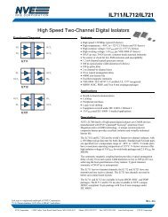
than 2 ns. Isoloop-isolators have up to<br />
four channels per package in a variety<br />
of device direction configurations.<br />
These standard devices are great for<br />
bus isolation, serial ADCs and DACs,<br />
and communication isolation. Figure 5<br />
shows typical RS-232 isolation.<br />
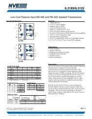
Specialty devices include isolated RS-<br />
422 and RS-485 communications<br />
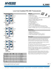
transceivers (see Figure 6).<br />
POWER ISOLATION<br />
<strong>Isolation</strong> can’t be achieved using a<br />
common power supply. This need creates<br />
a requirement for additional circuitry<br />
beyond the signal isolation.<br />
There must be a separate power supply<br />
for the circuitry on each side of the isolation<br />
barrier. Often this will be more<br />
expensive than the signal isolation.<br />
The simplest solution might be to<br />
purchase a DC-DC converter. In this<br />
case the converter is used as an isolator<br />
instead of converting from one voltage<br />
to another. Take your time choosing a<br />
converter; if you aren’t careful you<br />
can find yourself being locked into a<br />
single-source manufacturer, especially<br />
if you choose a converter <strong>with</strong> a weird<br />
pinout or physical size. An alternative<br />
might be to build one directly on-board.<br />
Both Linear Technologies and Maxim<br />
specialize in power products. Linear’s<br />
LT1424-5 is good to about 2 W. For<br />
lower currents up to a 1-W converter,<br />
take a look at Maxim’s MAX253. Few<br />
external components are required to use<br />
the MAX253 as a transformer driver<br />
Planar<br />
coil<br />
1″<br />
V CC<br />
Signal transmitted<br />
by magnetic field<br />
H<br />
Galvanic isolation<br />
by thin-film dielectric<br />
V CC<br />
Isolated<br />
output<br />
A<br />
GMR Resistors<br />
Figure 3—In a GMR, isolator data travels via a magnetic<br />
field through a dielectric isolation to affect the<br />
resistance elements arranged in a bridge configuration.<br />
for an isolated power supply circuit (see<br />
Figure 7). C&D Technologies makes an<br />
isolation transformer specially designed<br />
for the MAX253. The 78250 series<br />
transformer is available in 1500-V and<br />
4000-V isolation from Mouser.<br />
I made prototypes of the circuits in<br />
Figures 6 and 7 to create an isolated<br />
RS-485 transceiver for use <strong>with</strong> a<br />
microcontroller. <strong>Not</strong>ice the surface<br />
mount IL-485 mounted on a dip header<br />
in Photo 1. Pins 4, 5, 12, and 13 of the<br />
IL-485 are soldered to the header and<br />
the other pins are wired to the appropriate<br />
dip header pins. Using a dip header<br />
for surface mount parts makes them<br />
easier to handle and reuse elsewhere<br />
(after you get past the surgical wiring).<br />
Although the IL-485 is only available<br />
in the surface mount variety, the other<br />
devices are through-hole components. I<br />
measured typical required currents in<br />
the isoloop IL-485 circuit in Figure 6 and<br />
found the isolated RS-485 side required<br />
considerably less than 50 mA <strong>with</strong>out<br />
any load on the twisted pair. Using<br />
the isolated voltage to supply the termination<br />
load adds 50 mA to the load<br />
requirements of the MAX253 isolated<br />
supply. The MAX253 circuit easily supplied<br />
this current at just over 5 V after<br />
the Schottky rectifier drop, thanks to<br />
the 1:1.31 winding of the transformer.<br />
No regulator is needed because this is<br />
Photo 1—Mounting an SMD on a DIP header makes it<br />
easy to work <strong>with</strong>.<br />
2 Issue 142 May 2002 CIRCUIT CELLAR ® www.circuitcellar.com
Figure 5—The IL-712 contains Z isolators, which can easily be used <strong>with</strong> a MAX-232 for serial isolation. An additional<br />
IL-712 will add isolation for hardware handshaking.<br />
<strong>with</strong>in the recommended range for the<br />
IL-485 (4.5–5.5 VDC) and well below<br />
the 7-VDC absolute maximum rating.<br />
The 78253 transformer from C&D<br />
Technologies is rated at 200 mA, so<br />
there is plenty of overhead even <strong>with</strong><br />
a heavy RS-485 termination. Large<br />
spikes were seen on the isolated side<br />
of the MAX253’s circuitry, but a series<br />
choke tamed them nicely (see Photo 2).<br />
Are isolation techniques necessary?<br />
In many situations, they aren’t necessary.<br />
Overlooking the more obvious<br />
safety issues (such as distances between<br />
devices) in some applications increases<br />
the potential for ground loop problems.<br />
GROUND LOOPS<br />
When equipment using different<br />
power supplies is tied together (<strong>with</strong> a<br />
common ground connection) there is a<br />
Photo 2—The upper trace shows 0.5-V spikes on the<br />
isolated output of the power supply. The lower trace<br />
shows the same output after a series choke.<br />
potential for ground loop currents to<br />
exist. This is an induced current in<br />
the common ground line as a result of<br />
a difference in ground potentials at each<br />
piece of equipment. (<strong>Not</strong>e: improper<br />
house wiring can cause ground loops<br />
when the neutral side of the line, or<br />
the ground, is not properly grounded.)<br />
We normally think of all grounds as<br />
being of the same potential. If this were<br />
so, there would never be a ground<br />
loop problem. Here at Circuit Cellar<br />
world headquarters, I’ve measured a<br />
considerable difference between the<br />
grounds of different outlets (and different<br />
phases) <strong>with</strong>in the same room.<br />
There are a number of reasons that<br />
could explain these findings. It doesn’t<br />
take a large difference in potential to<br />
cause ground currents to<br />
flow through a common<br />
ground connection. The<br />
potentials (and currents<br />
created) are also load related,<br />
so, most of the time,<br />
these currents will not be<br />
steady state.<br />
If sensor circuitry is<br />
based on its own ground as<br />
a reference and the system<br />
ground is not the same,<br />
you can’t expect to be able<br />
to take accurate measurements.<br />
You’d think that<br />
making the common<br />
ground heavier might be<br />
the solution. But, in many cases, this<br />
only increases ground loop current.<br />
Breaking this common ground is a better<br />
solution. However, if the common<br />
ground connection is broken, the differential<br />
in ground potentials remains<br />
and will affect any signal between the<br />
two pieces of equipment. You need to<br />
isolate the grounds as well as the<br />
other signals, otherwise you run the<br />
risk of exceeding the maximum or<br />
minimum allowable input specs.<br />
To eliminate ground loop problems<br />
when connecting devices using grounded<br />
supplies located on different circuits,<br />
do not make a common ground connection<br />
between the devices you want<br />
connected. Although this eliminates<br />
ground currents from flowing between<br />
devices, it creates a problem for the<br />
signals, which are ground referenced.<br />
Take communications interfaces for<br />
instance. RS-232 circuitry must have a<br />
ground connection because it is the reference<br />
for the remaining signal lines.<br />
On the other hand, RS-422/485 uses<br />
differential signals not referenced to<br />
ground. You can use this twisted pair<br />
connection <strong>with</strong>out a common ground<br />
unless there is a difference of more<br />
than 7 V between them. The RS-485<br />
receivers can <strong>with</strong>stand up to a 7-V<br />
ground-referenced difference before<br />
exceeding the maximum or minimum<br />
ratings. Would you gamble <strong>with</strong> circuit<br />
failure over a 7-V spread? This is where<br />
signal isolation payoff comes into play.<br />
When dealing <strong>with</strong> sensors, ground<br />
loop currents cause changes in an analog<br />
signal. These changes often look<br />
like signal noise. A ground loop can<br />
Figure 6—The IL-485 replaces the RS-485 devices when an isolated<br />
twisted pair network is needed.<br />
www.circuitcellar.com CIRCUIT CELLAR ® Issue 142 May 2002 3
Figure 7—Maxim’s MAX253 makes a great isolation<br />
supply. C&D Technologies has a transformer specifically<br />
for use <strong>with</strong> the MAX253.<br />
even be caused by a mechanical and<br />
electrical (if uninsulated) connection<br />
to a grounded object being sensed. To<br />
eliminate all of the common ground<br />
loop problems between sensor and<br />
measurement circuitry, always power<br />
and measure sensors <strong>with</strong> the same<br />
local supply. By measuring right at the<br />
sensor, lengthy leads will carry digital<br />
data (easily isolated) rather than analog<br />
data (difficult to isolate).<br />
The available IsoLoop products will<br />
handle most isolation problems. Besides<br />
the speed advantage over most<br />
optoisolators, the IsoLoop products<br />
have a latching output. Because the output<br />
state is latched on magnetic field<br />
change (controlled by the input to the<br />
device), even if the power is removed<br />
from the input side, the output side’s<br />
logic state would remain latched (memorized).<br />
This would require an extra set<br />
of latches when using an optoisolator.<br />
<strong>NVE</strong> introduced its first GMR product<br />
in 1994. These days, GMR sensors<br />
compete <strong>with</strong> Hall effect devices for<br />
many magnetic sensing applications<br />
and additional research continues on<br />
the use of GMR materials for magnetoresistive<br />
random access memory<br />
(MRAM) technology. Can you say core<br />
memory? What goes around…. I<br />
Jeff Bachiochi (pronounced BAH-key-<br />
AH-key) is an electrical engineer on<br />
Circuit Cellar’s engineering staff. His<br />
background includes product design<br />
and manufacturing. He may be reached<br />
at jeff.bachiochi@circuitcellar.com.<br />
SOURCE<br />
IsoLoop high-speed digital isolators<br />
<strong>NVE</strong> <strong>Corporation</strong><br />
1(800) 467-7141<br />
www.isoloop.com<br />
Circuit Cellar, the Magazine for Computer<br />
Applications. Reprinted by permission.<br />
For subscription information,<br />
call (860) 875-2199, or www.circuitcellar.com.<br />
Entire contents copyright ©2001 Circuit Cellar<br />
Inc. All rights reserved.<br />
4 Issue 142 May 2002 CIRCUIT CELLAR ® www.circuitcellar.com