GMR Switch - NVE Corporation
GMR Switch - NVE Corporation
GMR Switch - NVE Corporation

Create successful ePaper yourself
Turn your PDF publications into a flip-book with our unique Google optimized e-Paper software.
<strong>GMR</strong> <strong>Switch</strong> Precision Digital Sensors<br />
<strong>GMR</strong> <strong>Switch</strong> Precision Digital Sensors<br />
When <strong>GMR</strong> sensor elements are combined with digital on-board signal processing<br />
electronics, the result is the <strong>GMR</strong> <strong>Switch</strong>. The <strong>GMR</strong> <strong>Switch</strong> offers unmatched precision<br />
and flexibility in magnetic field sensing.<br />
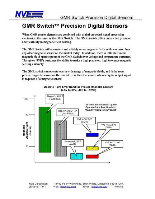
The <strong>GMR</strong> <strong>Switch</strong> will accurately and reliably sense magnetic fields with less error than<br />
any other magnetic sensor on the market today. In addition, there is little shift in the<br />
magnetic field operate point of the <strong>GMR</strong> <strong>Switch</strong> over voltage and temperature extremes.<br />
This gives <strong>NVE</strong>’s customer the ability to make a high precision, high tolerance magnetic<br />
sensing assembly.<br />
The <strong>GMR</strong> switch can operate over a wide range of magnetic fields, and is the most<br />
precise magnetic sensor on the market. It is the clear choice when a digital output signal<br />
is required of a magnetic sensor.<br />
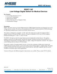
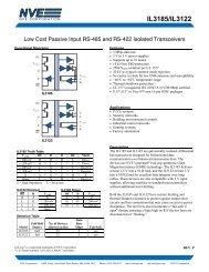
Operate Point Error Band for Typical Magnetic Sensors<br />
(4.5V to 30V, -40C to +125C)<br />
200<br />
150<br />
Allegro 3141LLT<br />
(Hall Effect)<br />
Honeywell SS441A<br />
(Hall Effect)<br />
The <strong>GMR</strong> <strong>Switch</strong> Holds Tighter<br />
Operate Point Specifications<br />
Than Any Competing Product!<br />
Magnetic<br />
Operate Point<br />
(Gauss)<br />
<strong>NVE</strong> AD023-00<br />
(<strong>GMR</strong>)<br />
<strong>NVE</strong> AD022-00<br />
(<strong>GMR</strong>)<br />
50<br />
Honeywell 2SSP<br />
(AMR)<br />
<strong>NVE</strong> AD021-00<br />
(<strong>GMR</strong>)<br />
<strong>NVE</strong> <strong>Corporation</strong> 11409 Valley View Road, Eden Prairie, Minnesota 55344 USA<br />
(800) 467-7141 Web: www.nve.com Email: info@nve.com 11/15/02
<strong>GMR</strong> <strong>Switch</strong> Precision Digital Sensors<br />
Quick Reference: <strong>GMR</strong> <strong>Switch</strong> Digital Sensors<br />
The following table lists some of <strong>NVE</strong>’s most popular <strong>GMR</strong> <strong>Switch</strong> products and their<br />
key specifications:<br />
Part Number<br />
Typical<br />
Magnetic<br />
Operate<br />
Point<br />
(Oe 1 )<br />
Typical<br />
Magnetic<br />
Release<br />
Point<br />
(Oe 1 )<br />
Output<br />
Type 2<br />
Maximum<br />
Operation<br />
Temperature<br />
(°C)<br />
Package<br />
Type 3<br />
<strong>NVE</strong> AD004-02 20 10 Sink 125 SOIC8<br />
<strong>NVE</strong> AD005-02 40 25 Sink 125 SOIC8<br />
<strong>NVE</strong> AD021-00 20 10 Sink 125 MSOP8<br />
<strong>NVE</strong> AD022-00 40 25 Sink 125 MSOP8<br />
<strong>NVE</strong> AD024-00 28 14 Sink 125 MSOP8<br />
<strong>NVE</strong> AD124-00 28 14 Source 125 MSOP8<br />
<strong>NVE</strong> AD621-00 20 10 Sink + 125 MSOP8<br />
Source<br />
<strong>NVE</strong> AD824-00 28 18 2 Sinks + 125 MSOP8<br />
SCP<br />
<strong>NVE</strong> ADH025-00 11 5 Sink 150 MSOP8<br />
Notes:<br />
1. 1 Oersted (Oe) = 1 Gauss in air<br />
2. Output Types:<br />
Sink = Up to 20mA current sink<br />
Source = Up to 20mA current source<br />
SCP = Short Circuit Protection available for external transistor<br />
3. See Appendix for package dimensions<br />
Note on Availability of Products<br />
<strong>NVE</strong> keeps about 25 of the most popular types of <strong>GMR</strong> <strong>Switch</strong> products in<br />
stock at our manufacturing facility. However, because there are over 100<br />
different varieties of <strong>GMR</strong> <strong>Switch</strong> parts, some part numbers may require a 6 to 8<br />
week lead time before production quantities are available. Please contact <strong>NVE</strong><br />
for further information.<br />
<strong>NVE</strong> <strong>Corporation</strong> 11409 Valley View Road, Eden Prairie, Minnesota 55344 USA<br />
(800) 467-7141 Web: www.nve.com Email: info@nve.com 11/15/02
<strong>GMR</strong> <strong>Switch</strong> Product Selection Guide<br />
<strong>GMR</strong> <strong>Switch</strong> Product Selection Guide<br />
<strong>NVE</strong>’s <strong>GMR</strong> <strong>Switch</strong> is available in a wide range of packaging, output type, and magnetic<br />
trigger field varieties. The purpose of this selection guide is to explain the different<br />
output and packaging options, as well as to provide information on how to specify the<br />
correct part number when ordering.<br />
All <strong>NVE</strong> <strong>GMR</strong> <strong>Switch</strong> product part numbers follow the same general form. As shown<br />
below, the first “x” in the part number specifies output type and available voltage<br />
regulator output, the next two x’s specify trigger field and direction of sensitivity, and the<br />
last pair specify the package type. The following sections define these variations in<br />
detail.<br />
<strong>NVE</strong> ADxxx-xx<br />
Output Type and<br />
Available Regulator<br />
Trigger Field, Direction of<br />
Sensitivity, Low Voltage Operation<br />
Package Type<br />
Output Type and Available Regulator<br />
The first numeric digit of the part number <strong>NVE</strong> ADxxx-xx specifies the output type, and<br />
the availability of a regulated voltage supply on a separate pin. The following four output<br />
types are available:<br />
20 mA Current Sink<br />
20 mA Current Source<br />
Separate 20 mA Sink and Source<br />
Two Separate 20 mA Sinks<br />
All outputs turn ON when the magnetic field is applied. An output that turns OFF when<br />
the magnetic field is applied is available as a custom product; please consult <strong>NVE</strong>.<br />
Some of <strong>NVE</strong>’s <strong>GMR</strong> <strong>Switch</strong>es also feature a regulated supply voltage available external<br />
to the part on a separate pin. This regulator provides a 5.8V reference capable of<br />
supplying up to 3 mA of drive current. This regulated output may be used to run an LED<br />
or other low power device.<br />
<strong>NVE</strong> <strong>Corporation</strong> 11409 Valley View Road, Eden Prairie, Minnesota 55344 USA<br />
(800) 467-7141 Web: www.nve.com Email: info@nve.com 11/15/02
<strong>GMR</strong> <strong>Switch</strong> Product Selection Guide<br />
In addition to these options, <strong>NVE</strong> recently introduced a <strong>GMR</strong> <strong>Switch</strong> that has provisions<br />
for shutting down an external power transistor in case a short circuit is detected. This is<br />
useful in applications where the finished sensor assembly must be “bulletproof,” or<br />
immune to improper connection.<br />
The following table defines the first digit in the <strong>NVE</strong> AD part number:<br />
<strong>NVE</strong> AD x xx-xx<br />
Number Meaning<br />
0 20mA Current Sink<br />
1 20 mA Current Source<br />
2 Separate 20mA Current Sink and 20mA Current Source<br />
3 Two Separate 20mA Current Sinks<br />
4 20mA Current Sink + Regulated Output Voltage<br />
5 20 mA Current Source + Regulated Output Voltage<br />
6 Separate 20mA Current Sink and 20mA Current Source +<br />
Regulated Output Voltage<br />
7 Two Separate 20mA Current Sinks + Regulated Output<br />
Voltage<br />
8 Two Separate 20mA Current Sinks + Regulated Output<br />
Voltage + Short Circuit Detection and Shut-Off<br />
9 Separate 20mA Current Sink and 20mA Current Source +<br />
Regulated Output Voltage + Short Circuit Detection and<br />
Shut-Off<br />
Trigger Field, Direction of Sensitivity, Low Voltage Operation<br />
The second and third numeric digits of the part number <strong>NVE</strong> ADxxx-xx specify the<br />
magnetic trigger field and direction of sensitivity of the part. Five different magnetic<br />
trigger fields are available for the <strong>GMR</strong> <strong>Switch</strong>:<br />
- 10 Gauss (10 Oe, 1.0 mT, 0.8 kA/m)<br />
- 20 Gauss (20 Oe, 2.0 mT, 1.6 kA/m)<br />
- 28 Gauss (28 Oe, 2.8 mT, 2.23 kA/m)<br />
- 40 Gauss (40 Oe, 4.0 mT, 3.2 kA/m)<br />
- 80 Gauss (80 Oe, 8.0 mT, 6.4 kA/m)<br />
Other magnetic trigger field levels ranging up to 250 Gauss are available on a custom<br />
basis; please contact <strong>NVE</strong>.<br />
<strong>NVE</strong> <strong>Corporation</strong> 11409 Valley View Road, Eden Prairie, Minnesota 55344 USA<br />
(800) 467-7141 Web: www.nve.com Email: info@nve.com 11/15/02
<strong>GMR</strong> <strong>Switch</strong> Product Selection Guide<br />
In addition to defining the magnetic operate point, these two digits are used to define the<br />
direction of sensitivity and optional low voltage operation. The <strong>GMR</strong> <strong>Switch</strong> can be<br />
ordered in Standard Axis or Cross Axis directions of sensitivity; for definitions please see<br />
<strong>NVE</strong> AD Series Sensitivity Direction and Pin Configuration later in this section.<br />
<strong>NVE</strong> also makes a <strong>GMR</strong> <strong>Switch</strong> with the on-chip voltage regulator bypassed. This limits<br />
the voltage range of the part, but allows it to operate at voltages as low as 3.0V.<br />
The following table defines the second and third digits in the <strong>NVE</strong> AD part number:<br />
<strong>NVE</strong> AD x xx-xx<br />
Number Meaning<br />
04 20 Gauss OP, Standard Direction of Sensitivity<br />
05 40 Gauss OP, Standard Direction of Sensitivity<br />
06 80 Gauss OP, Standard Direction of Sensitivity<br />
20 28 Gauss OP, Standard Direction of Sensitivity<br />
21 20 Gauss OP, Cross Axis Direction of Sensitivity<br />
22 40 Gauss OP, Cross Axis Direction of Sensitivity<br />
23 80 Gauss OP, Cross Axis Direction of Sensitivity<br />
24 28 Gauss OP, Cross Axis Direction of Sensitivity<br />
25 10 Gauss OP, Cross Axis Direction of Sensitivity<br />
(ADH Series Only; see page 38)<br />
81 20 Gauss OP, Cross Axis Direction of Sensitivity, Low Volt<br />
82 40 Gauss OP, Cross Axis Direction of Sensitivity, Low Volt<br />
83 80 Gauss OP, Cross Axis Direction of Sensitivity, Low Volt<br />
84 28 Gauss OP, Cross Axis Direction of Sensitivity, Low Volt<br />
Note: For parts that operate at 10 Gauss, see the following section describing the <strong>NVE</strong><br />
ADH Series sensors.<br />
<strong>NVE</strong> AD Series Sensitivity Direction and Pin Configuration<br />
Pin configuration is for the <strong>NVE</strong> AD Series <strong>GMR</strong> <strong>Switch</strong>es is given in the following<br />
diagrams. In addition, most <strong>GMR</strong> <strong>Switch</strong> parts are available with a choice of two<br />
directions of sensitivity. “Standard” direction of sensitivity is defined as the direction<br />
parallel to the edge of the package containing the pins. “Cross-Axis” direction of<br />
<strong>NVE</strong> <strong>Corporation</strong> 11409 Valley View Road, Eden Prairie, Minnesota 55344 USA<br />
(800) 467-7141 Web: www.nve.com Email: info@nve.com 11/15/02
<strong>GMR</strong> <strong>Switch</strong> Product Selection Guide<br />
sensitivity is defined as the direction perpendicular to the edge of the package containing<br />
the pins. Pin configuration and sensitivity direction for the SOIC8 and MSOP8 packages<br />
are defined in the drawings below:<br />
<strong>NVE</strong> AD0xx-xx through <strong>NVE</strong> AD7xx-xx, <strong>NVE</strong> ADH0xx-xx:<br />
N/C<br />
VCC<br />
VCC<br />
Sink(1)<br />
Source<br />
Sink(2)<br />
Standard Axis<br />
N/C*<br />
Vreg<br />
Source<br />
Sink(2)<br />
Cross Axis<br />
N/C*<br />
Vreg<br />
Ground<br />
Sink(1)<br />
N/C<br />
Ground<br />
Note: In the case of a Standard Axis Part with the Vreg pin option, Sink(1) will appear at the pin labelled N/C*<br />
<strong>NVE</strong> AD8xx-xx through <strong>NVE</strong> AD9xx-xx:<br />
Cap2<br />
VCC<br />
Cap2<br />
VCC<br />
Cap<br />
AD8xx-xx<br />
ShortH<br />
Cap<br />
AD9xx-xx<br />
ShortL<br />
Sink(2)<br />
Cross Axis<br />
Sink(1)<br />
Source<br />
Cross Axis<br />
Sink<br />
Ground<br />
Vreg<br />
Ground<br />
Vreg<br />
Pin configuration and sensitivity direction for the AD0xx-10 TDFN6 package are defined<br />
in the drawing below:<br />
VCC<br />
AD0xx-10<br />
Out<br />
N/C<br />
AD0xx-10<br />
VCC<br />
N/C<br />
N/C<br />
Cross Axis<br />
Test<br />
Ground<br />
N/C<br />
Ground<br />
Standard Axis<br />
N/C<br />
Out<br />
<strong>NVE</strong> <strong>Corporation</strong> 11409 Valley View Road, Eden Prairie, Minnesota 55344 USA<br />
(800) 467-7141 Web: www.nve.com Email: info@nve.com 11/15/02
Package Type<br />
<strong>GMR</strong> <strong>Switch</strong> Product Selection Guide<br />
<strong>NVE</strong> <strong>GMR</strong> <strong>Switch</strong>es are available in three different packages: an SOIC 8 pin package,<br />
an MSOP 8 pin small outline package, and a TDFN 6 pin ultra-miniature package.<br />
Package drawings are shown in the Appendix.<br />
The following table defines the last two digits in the <strong>NVE</strong> AD part number:<br />
<strong>NVE</strong> AD x xx-xx<br />
Number Package Type<br />
00 MSOP8<br />
02 SOIC8<br />
10 1 TDFN6<br />
Note 1 : At this time, the TDFN6 package is only available in AD0xx-10 configuration.<br />
In addition to these three package types, <strong>NVE</strong> offers a custom version of the MSOP8<br />
package for the <strong>NVE</strong> AD024-00 part. In this version, the BD012-00, all three<br />
connections are made on one side of the package, and the pins on the other side of the<br />
package are clipped off flush with the body of the package. This allows the user to<br />
position the sensing element as close to the edge of a circuit board or assembly as<br />
possible. A pinout of this package is shown below:<br />
VCC<br />
BD012-00<br />
Cross Axis<br />
N/C*<br />
Out<br />
Ground<br />
The maximum length of the clipped leads is 0.30mm, leading to an overall package<br />
length of 4.25mm, as compared to 4.90mm for the normal MSOP8 package. This part is<br />
available in tape and reel format only.<br />
Other versions of the <strong>GMR</strong> <strong>Switch</strong> may be available in this package configuration on a<br />
special order basis. Please contact <strong>NVE</strong> for further information.<br />
<strong>NVE</strong> <strong>Corporation</strong> 11409 Valley View Road, Eden Prairie, Minnesota 55344 USA<br />
(800) 467-7141 Web: www.nve.com Email: info@nve.com 11/15/02
<strong>GMR</strong> <strong>Switch</strong> Product Selection Guide<br />
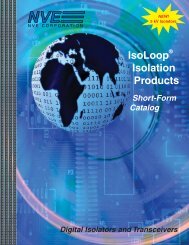
Characteristics Over Voltage and Temperature<br />
Typical Operate Points (OP) and Release Points (RP)<br />
AD004 and AD005<br />
Applied Field<br />
(Oersteds)<br />
50<br />
40<br />
30<br />
20<br />
10<br />
Ambient Temperature = 25C<br />
AD005 OP<br />
AD005 RP<br />
AD004 OP<br />
AD004 RP<br />
0<br />
5 10 15 20 25 30<br />
Supply Voltage<br />
Operate Point (OP) and Release Point (RP) Variation<br />
Over Temperature<br />
50<br />
Applied Field (Oe)<br />
40<br />
30<br />
20<br />
10<br />
0<br />
-40 0 40 80 120<br />
Temperature (C)<br />
AD005 OP<br />
AD005 RP<br />
AD004 OP<br />
AD004 RP<br />
<strong>NVE</strong> <strong>Corporation</strong> 11409 Valley View Road, Eden Prairie, Minnesota 55344 USA<br />
(800) 467-7141 Web: www.nve.com Email: info@nve.com 11/15/02
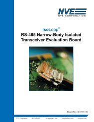
<strong>GMR</strong> <strong>Switch</strong> Product Selection Guide<br />
Operating Temperature Derating Curves for SOIC8,<br />
MSOP8, and TDFN6 Packages in Free Air<br />
Temperature (C)<br />
130<br />
120<br />
110<br />
100<br />
90<br />
80<br />
5 10 15 20 25 30<br />
Supply Voltage (V)<br />
SOIC8<br />
MSOP8<br />
and<br />
TDFN6<br />
Maximum Output<br />
Current (mA)<br />
25<br />
20<br />
15<br />
Output Current Derating Curve<br />
10<br />
4.5 6 7.5 9 10.5<br />
Supply Voltage (V)<br />
(Continues to 30V)<br />
<strong>NVE</strong> <strong>Corporation</strong> 11409 Valley View Road, Eden Prairie, Minnesota 55344 USA<br />
(800) 467-7141 Web: www.nve.com Email: info@nve.com 11/15/02
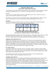
AD0xx-xx to AD7xx-xx<br />
AD0xx-xx to AD7xx-xx<br />
Features:<br />
⇒ Precision Magnetic Operate Point<br />
⇒ Excellent Temperature and Voltage Performance<br />
⇒ Digital Outputs<br />
⇒ Frequency Response 0 to 250KHz<br />
⇒ Optional Voltage Regulator Output<br />
⇒ Optional Low Voltage Version<br />
⇒ Small, Low Profile Surface Mount Packages<br />
Applications:<br />
⇒ General Digital Position Sensing<br />
⇒ Pneumatic Cylinder Position Sensing<br />
⇒ Speed Sensing<br />
Description:<br />
The <strong>NVE</strong> AD0xx-xx to AD7xx-xx <strong>GMR</strong> <strong>Switch</strong>es are digital output magnetometers that<br />
offers precision operate points over all temperature and input voltage conditions. They<br />
are available with magnetic trigger fields from 20 to 80 Gauss, and four different output<br />
configurations, making them an extremely flexible and user-friendly design.<br />
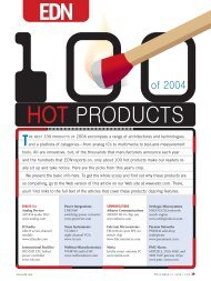
Functional Block Diagram (<strong>NVE</strong> AD0xx-xx to <strong>NVE</strong> AD7xx-xx,<br />
Except <strong>NVE</strong> AD08x-xx):<br />
Voltage<br />
Regulator<br />
(5.8V)<br />
Current Sinking<br />
Output<br />
4.5V to 30V<br />
<strong>GMR</strong><br />
Bridge<br />
Comparator<br />
<strong>NVE</strong> <strong>Corporation</strong> 11409 Valley View Road, Eden Prairie, Minnesota 55344 USA<br />
(800) 467-7141 Web: www.nve.com Email: info@nve.com 11/15/02
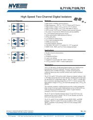
Functional Block Diagram (<strong>NVE</strong> AD08x-xx):<br />
AD0xx-xx to AD7xx-xx<br />
3.0V to 6.0V<br />
Current Sinking<br />
Output<br />
<strong>GMR</strong><br />
Bridge<br />
Comparator<br />
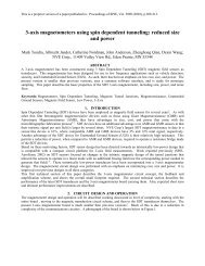
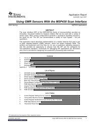
Output Characteristic as a Function of Magnetic<br />
Field, for AD024-00 <strong>GMR</strong> <strong>Switch</strong><br />
Output Current, mA<br />
(10V Supply, 1K Load Resistor)<br />
12<br />
10<br />
8<br />
ON OFF OFF ON<br />
6<br />
4<br />
2<br />
0<br />
-40 -20 0 20 40<br />
Applied Magnetic Field (Oe)<br />
Magnetic Characteristics:<br />
Typical Operate<br />
Point<br />
Minimum<br />
Operate Point<br />
Maximum Operate<br />
Point<br />
Minimum<br />
Differential 1,2<br />
20 15 25 5 14<br />
28 21 34 5 20<br />
40 30 50 5 25<br />
80 60 100 5 35<br />
Note: All Values in Oersteds (Oe); 1 Oe = 1 Gauss in Air<br />
Maximum<br />
Differential 1,2<br />
<strong>NVE</strong> <strong>Corporation</strong> 11409 Valley View Road, Eden Prairie, Minnesota 55344 USA<br />
(800) 467-7141 Web: www.nve.com Email: info@nve.com 11/15/02
AD0xx-xx to AD7xx-xx<br />
Electrical Specifications (<strong>NVE</strong> AD0xx-xx to <strong>NVE</strong> AD7xx-xx,<br />
except <strong>NVE</strong> AD08x-xx):<br />
Parameter Symbol Min Max Units Test Condition<br />
Supply Voltage 4 V CC 4.5 30 V Operating<br />
Supply Current, Single Output I CC 2.5 4.5 mA Output Off, V CC =12V<br />
Current Sinking Output 3 I O 0 20 mA 3 Operating<br />
Current Sourcing Output 3 I O 0 20 mA 3 Operating<br />
Output Leakage Current I LEAK 10 μA Output Off, V CC =12V<br />
Sinking Output Saturation Voltage V OL 0.4 V Output On, I OL =20mA<br />
Sourcing Output Saturation Voltage V OH V CC -2.5 V Output On, I OL =20mA<br />
Regulated Output Voltage 6 V REG 3.5 6.2 V Operating<br />
Regulated Output Current I REG 3.0 mA Operating<br />
Electrical Specifications (<strong>NVE</strong> AD08x-xx):<br />
Parameter Symbol Min Max Units Test Condition<br />
Supply Voltage V CC 3.0 6.0 V Operating<br />
Supply Current, Single Output I CC 0.7 1.2 mA Output Off, V CC =3V<br />
Supply Current, Single Output I CC 1.7 2.2 mA Output Off, V CC =6V<br />
Current Sinking Output 2 I O 0 20 mA 3 Operating<br />
Output Leakage Current I LEAK 10 μA Output Off, V CC =5V<br />
Sinking Output Saturation Voltage V OL 0.4 V Output On, I OL =20mA<br />
Absolute Maximum Ratings (<strong>NVE</strong> AD0xx-xx to <strong>NVE</strong> AD7xx-xx,<br />
except <strong>NVE</strong> AD08x-xx):<br />
Parameter Symbol Min Max Units<br />
Supply Voltage V CC 33 V<br />
Reverse Battery Voltage V RBP -33 V<br />
Current Sinking Output Off Voltage 33 V<br />
Current Sourcing Output Off Voltage 0 V<br />
Current Sinking Reverse Output Voltage -0.5 V<br />
Current Sourcing Reverse Output Voltage -0.5 V<br />
Continuous Output Current I 0 24 mA<br />
Operating Temperature Range 4 T A -40 125 °C<br />
Storage Temperature Range T S -65 150 °C<br />
Magnetic Field 5 H None Oe<br />
<strong>NVE</strong> <strong>Corporation</strong> 11409 Valley View Road, Eden Prairie, Minnesota 55344 USA<br />
(800) 467-7141 Web: www.nve.com Email: info@nve.com 11/15/02
AD0xx-xx to AD7xx-xx<br />
Absolute Maximum Ratings (<strong>NVE</strong> AD08x-xx):<br />
Parameter Symbol Min Max Units<br />
Supply Voltage V CC 7 V<br />
Reverse Battery Voltage V RBP -0.5 V<br />
Current Sinking Output Off Voltage 33 V<br />
Current Sinking Reverse Output Voltage -0.5 V<br />
Continuous Output Current I 0 24 mA<br />
Operating Temperature Range 4 T A -40 125 °C<br />
Storage Temperature Range T S -65 150 °C<br />
Magnetic Field 5 H None Oe<br />
Notes:<br />
1. Differential = Operate Point – Release Point<br />
2. Minimum Release Point for AD0xx-xx to AD7xx-xx, except AD08x-xx, = 5 Oe. Minimum Release<br />
Point for AD08x-xx = 3.5 Oe.<br />
3. Output current must be limited by a series resistor. Exceeding absolute maximum continuous output<br />
current ratings will result in damage to the part. See the figure in the <strong>GMR</strong> <strong>Switch</strong> Product Selection<br />
Guide for an output current derating curve.<br />
4. Thermal power dissipation for the packages used by <strong>NVE</strong> is 240°C/Watt for the SOIC8 package,<br />
and 320°C/Watt for the MSOP8 and TDFN6 packages. See the Figure on Ambient Temperature vs.<br />
Supply Voltage for derating information. Heat sinking the parts by attaching them to a PCB<br />
improves temperature performance.<br />
5. There is no maximum magnetic field that will cause damage to the device.<br />
6. If V CC >6.6V, V REG =5.8V. If V CC
AD8xx-xx to AD9xx-xx<br />
AD8xx-xx to AD9xx-xx<br />
Features:<br />
⇒ Short Circuit Detection and Shutoff of External Power Transistor<br />
⇒ Precision Magnetic Operate Point<br />
⇒ Excellent Temperature and Voltage Performance<br />
⇒ Digital Outputs<br />
⇒ Frequency Response 0 to 250KHz<br />
⇒ Small, Low Profile Surface Mount Packages<br />
Applications:<br />
⇒ General Digital Position Sensing<br />
⇒ Pneumatic Cylinder Position Sensing<br />
⇒ Speed Sensing<br />
Description:<br />
<strong>NVE</strong> AD8xx and AD9xx <strong>GMR</strong> <strong>Switch</strong>es are designed specifically for use with an<br />
external high current output transistor in industrial control environments. These parts<br />
provide the same precise magnetic performance <strong>NVE</strong>’s <strong>GMR</strong> <strong>Switch</strong> is known for, with<br />
the additional functionality of short circuit protection (SCP) for the output stage of the<br />
circuit. The protection circuit is designed to shut off the output stage when a short circuit<br />
condition exists; after a time interval specified by the user, the circuit turns back on. If<br />
the short circuit condition still exists, the output stage is again shut off and the cycle<br />
repeats. The use of this sensor, along with external reverse battery protection and<br />
overvoltage protection, results in a “bulletproof” sensor assembly. A functional block<br />
diagram of this sensor is shown below:<br />
VDD<br />
Vreg<br />
ShortH<br />
Comparator<br />
<strong>GMR</strong><br />
Bridge<br />
Comparator<br />
Sink1<br />
Cap2<br />
SCP Turn<br />
On Delay<br />
Sink2<br />
Cap<br />
Off State<br />
Timer<br />
Ground<br />
These digital sensors with SCP are available for use with current sinking or current<br />
sourcing outputs, in a range of magnetic field operate points. They are provided in an<br />
<strong>NVE</strong> <strong>Corporation</strong> 11409 Valley View Road, Eden Prairie, Minnesota 55344 USA<br />
(800) 467-7141 Web: www.nve.com Email: info@nve.com 11/15/02
AD8xx-xx to AD9xx-xx<br />
MSOP8 package, with the cross-axis direction of sensitivity. An LED driver to indicate<br />
the presence of the magnetic field is also standard on these products. An SOIC8 package<br />
and standard axis sensitivity are available on a special order basis.<br />
Typical Circuit Configuration:<br />
VDD<br />
Pin 1<br />
Cap2<br />
VDD<br />
R BIAS1<br />
R SHORT<br />
Cap<br />
Sink2<br />
AD821-00<br />
ShortH<br />
Sink1<br />
R BIAS2<br />
Ground<br />
Vreg<br />
R LED<br />
Output<br />
t 2 Cap<br />
t 1 Cap<br />
VDD<br />
Pin 1<br />
Cap2<br />
VDD<br />
Cap<br />
Source<br />
AD921-00<br />
ShortL<br />
Sink1<br />
Ground<br />
Vreg<br />
Output<br />
t 2 Cap<br />
t 1 Cap<br />
R LED<br />
R BIAS2<br />
R BIAS1<br />
R SHORT<br />
<strong>NVE</strong> <strong>Corporation</strong> 11409 Valley View Road, Eden Prairie, Minnesota 55344 USA<br />
(800) 467-7141 Web: www.nve.com Email: info@nve.com 11/15/02
Output Transistor Current in Short Circuit mode:<br />
AD8xx-xx to AD9xx-xx<br />
Output Transistor Current in Short Circuit<br />
Current (mA)<br />
300<br />
200<br />
100<br />
t 2<br />
t 1<br />
Time<br />
Notes:<br />
1. The t 2 Cap is used to delay the startup of the SCP circuitry, in order to avoid triggering the SCP<br />
circuitry on normal startup transients: see t 2 on the graph above. Typical value is 16V, 0.001μF, for<br />
a 35μs delay.<br />
2. The t 1 Cap is used to set the “Off” time of the SCP circuitry; see t 1 on the graph above. Typical<br />
value is 16V, 0.01μF, for a 15ms Off time.<br />
3. The voltage across R SHORT is monitored by the IC; if this voltage exceeds 145mV (typical), the SCP<br />
circuitry is activated. Typical value of R SHORT is 0.47 Ohms, 1/16 watt. This will result in SCP<br />
circuitry turning on at about 300mA of output current.<br />
4. R BIAS1 and R BIAS2 are used to bias the output transistor. Typical values for R BIAS1 and R BIAS2 are 16K<br />
and 3K, respectively, to supply 1mA drive to the output transistor.<br />
5. R LED is sized for whatever LED current is required by the user; maximum of 3 mA.<br />
Magnetic Characteristics:<br />
Typical Operate<br />
Point<br />
Minimum<br />
Operate Point<br />
Maximum<br />
Operate Point<br />
Minimum<br />
Differential 1,2<br />
Maximum<br />
Differential 1,2<br />
20 15 25 5 14<br />
28 21 32.5 5 15<br />
40 30 50 5 25<br />
80 60 100 5 35<br />
Note: All Values in Oersteds (Oe); 1 Oe = 1 Gauss in Air<br />
<strong>NVE</strong> <strong>Corporation</strong> 11409 Valley View Road, Eden Prairie, Minnesota 55344 USA<br />
(800) 467-7141 Web: www.nve.com Email: info@nve.com 11/15/02
Electrical Specifications:<br />
AD8xx-xx to AD9xx-xx<br />
Parameter Symbol Min Max Units Test Condition<br />
Supply Voltage 4 V CC 4.5 30 V Operating<br />
Supply Current I CC 1.75 3.5 mA Output Off, V CC =12V<br />
Current Sinking Output 2 I O 0 2.0 mA 3 Operating<br />
Current Sourcing Output 2 I O 0 2.0 mA 3 Operating<br />
Output Leakage Current I LEAK 10 μA Output Off, V CC =12V<br />
Sinking Output Saturation Voltage V OL 0.4 V Output On, I OL =2mA<br />
Sourcing Output Saturation Voltage V OH V CC -2.0 V Output On, I OL =2mA<br />
Regulated Output Voltage 6 V REG 3.5 6.0 V Operating<br />
Regulated Output Current I REG 3.0 mA Operating<br />
Short High Voltage ShortH 0.12 0.17 V Output On<br />
Short Low Voltage ShortL 0.12 0.17 V Output On<br />
Absolute Maximum Ratings:<br />
Parameter Symbol Min Max Units<br />
Supply Voltage V CC 33 V<br />
Reverse Battery Voltage V RBP -0.5 V<br />
Current Sinking Output Off Voltage 33 V<br />
Current Sourcing Output Off Voltage 0 V<br />
Current Sinking Reverse Output Voltage -0.5 V<br />
Current Sourcing Reverse Output Voltage -0.5 V<br />
Continuous Output Current I 0 5 mA<br />
Operating Temperature Range 4 T A -40 125 °C<br />
Storage Temperature Range T S -65 135 °C<br />
Magnetic Field 5 H None Oe<br />
Notes:<br />
1. Differential = Operate Point – Release Point<br />
2. Minimum Release Point for AD8xx-xx to AD9xx-xx = 5 Oe.<br />
3. Output current must be limited by a series resistor. Exceeding absolute maximum continuous output<br />
current ratings will result in damage to the part.<br />
4. Thermal power dissipation for the packages used by <strong>NVE</strong> is 240°C/Watt for the SOIC8 package, and<br />
320°C/Watt for the MSOP8 and TDFN6 packages. See the Figure on Ambient Temperature vs. Supply<br />
Voltage for derating information. Heat sinking the parts by attaching them to a PCB improves<br />
temperature performance.<br />
5. There is no maximum magnetic field that will cause damage to the device.<br />
6. If V CC >6.6V, V REG =5.8V. If V CC
ADH0xx-xx<br />
Features:<br />
⇒ Precision Low Field Magnetic Operate Point<br />
⇒ Excellent Temperature and Voltage Performance<br />
⇒ Digital Output<br />
⇒ Frequency Response 0 to 250KHz<br />
⇒ Small, Low Profile Surface Mount Packages<br />
Applications:<br />
⇒ Low Field Digital Position Sensing<br />
⇒ Pneumatic Cylinder Position Sensing<br />
⇒ Speed Sensing<br />
Description:<br />
The <strong>NVE</strong> ADH0xx Series <strong>GMR</strong> <strong>Switch</strong> uses <strong>NVE</strong>’s high sensitivity, high temperature<br />
<strong>GMR</strong> material to provide a very low magnetic field operate point. It offers the same<br />
precision operate points over all temperature and input voltage conditions as our other<br />
<strong>GMR</strong> <strong>Switch</strong> products. It is available in standard form as the <strong>NVE</strong> ADH025-00 with a<br />
magnetic trigger field of 10 Gauss, a current sinking output, and a cross axis<br />
configuration. Custom versions with trigger fields ranging from 6 to 40 Gauss, and<br />
different output options and sensitivity directions could be manufactured for specific<br />
customer requirements; please contact <strong>NVE</strong> for details.<br />
Note: Functional Block Diagram for the <strong>NVE</strong> ADH0xx-xx Series sensors is the same as<br />
for the <strong>NVE</strong> AD0xx-xx sensors.<br />
Output Characteristic as a Function of Magnetic<br />
Field, ADH025-00<br />
Output Current, mA<br />
(10V Supply, 1K Load Resistor)<br />
12<br />
10<br />
8<br />
6<br />
4<br />
2<br />
ON<br />
OFF OFF ON<br />
0<br />
-14 -12 -10 -8 -6 -4 -2 0 2 4 6 8 10 12 14<br />
Applied Magnetic Field (Oe)<br />
<strong>NVE</strong> <strong>Corporation</strong> 11409 Valley View Road, Eden Prairie, Minnesota 55344 USA<br />
(800) 467-7141 Web: www.nve.com Email: info@nve.com 11/15/02
Magnetic Characteristics, <strong>NVE</strong> ADH025-00:<br />
Typical Operate<br />
Point<br />
Minimum<br />
Operate Point<br />
Maximum<br />
Operate Point<br />
Minimum<br />
Differential 1<br />
10 8 12 3.5 10<br />
Note: All Values in Oersteds (Oe); 1 Oe = 1 Gauss in Air<br />
Electrical Specifications, <strong>NVE</strong> ADH0xx-xx:<br />
Maximum<br />
Differential 1<br />
Parameter Symbol Min Max Units Test Condition<br />
Supply Voltage 4 V CC 4.5 30 V Operating<br />
Supply Current, Single Output I CC 3.0 6.0 mA Output Off, V CC =12V<br />
Current Sinking Output 3 I O 0 20 mA 3 Operating<br />
Output Leakage Current I LEAK 10 μA Output Off, V CC =12V<br />
Sinking Output Saturation Voltage V OL 0.4 V Output On, I OL =20mA<br />
Absolute Maximum Ratings:<br />
Parameter Symbol Min Max Units<br />
Supply Voltage V CC 33 V<br />
Reverse Battery Voltage V RBP -33 V<br />
Current Sinking Output Off Voltage 33 V<br />
Current Sourcing Output Off Voltage 0 V<br />
Current Sinking Reverse Output Voltage -0.5 V<br />
Current Sourcing Reverse Output Voltage -0.5 V<br />
Continuous Output Current I 0 24 mA<br />
Operating Temperature Range 4 T A -40 125 °C<br />
Storage Temperature Range T S -65 150 °C<br />
Magnetic Field 5 H None Oe<br />
Notes:<br />
1. Differential = Operate Point – Release Point<br />
2. Minimum Release Point for ADH0xx-xx = 2.0 Oe.<br />
3. Output current must be limited by a series resistor. Exceeding absolute maximum continuous output<br />
current ratings will result in damage to the part. See the figure in the <strong>GMR</strong> <strong>Switch</strong> Product Selection<br />
Guide for an output current derating curve.<br />
4. Thermal power dissipation for the packages used by <strong>NVE</strong> is 240°C/Watt for the SOIC8 package,<br />
and 320°C/Watt for the MSOP8 and TDFN6 packages. See the Figure on Ambient Temperature vs.<br />
Supply Voltage for derating information. Heat sinking the parts by attaching them to a PCB<br />
improves temperature performance.<br />
5. There is no maximum magnetic field that will cause damage to the device.<br />
<strong>NVE</strong> <strong>Corporation</strong> 11409 Valley View Road, Eden Prairie, Minnesota 55344 USA<br />
(800) 467-7141 Web: www.nve.com Email: info@nve.com 11/15/02