Instruction Sheet - Temporary mount assembly for Flo-Dar - Hachflow
Instruction Sheet - Temporary mount assembly for Flo-Dar - Hachflow
Instruction Sheet - Temporary mount assembly for Flo-Dar - Hachflow

You also want an ePaper? Increase the reach of your titles
YUMPU automatically turns print PDFs into web optimized ePapers that Google loves.
<strong>Instruction</strong> <strong>Sheet</strong><br />
<strong>Temporary</strong> <strong>mount</strong> <strong>assembly</strong> <strong>for</strong> FLO-DAR sensor<br />
DOC306.53.00786<br />
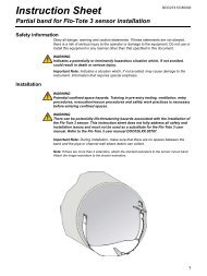
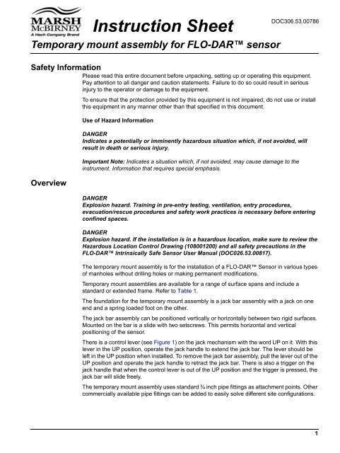
Safety In<strong>for</strong>mation<br />
Please read this entire document be<strong>for</strong>e unpacking, setting up or operating this equipment.<br />
Pay attention to all danger and caution statements. Failure to do so could result in serious<br />
injury to the operator or damage to the equipment.<br />
Overview<br />
To ensure that the protection provided by this equipment is not impaired, do not use or install<br />
this equipment in any manner other than that specified in this document.<br />
Use of Hazard In<strong>for</strong>mation<br />
DANGER<br />
Indicates a potentially or imminently hazardous situation which, if not avoided, will<br />
result in death or serious injury.<br />
Important Note: Indicates a situation which, if not avoided, may cause damage to the<br />
instrument. In<strong>for</strong>mation that requires special emphasis.<br />
DANGER<br />
Explosion hazard. Training in pre-entry testing, ventilation, entry procedures,<br />
evacuation/rescue procedures and safety work practices is necessary be<strong>for</strong>e entering<br />
confined spaces.<br />
DANGER<br />
Explosion hazard. If the installation is in a hazardous location, make sure to review the<br />
Hazardous Location Control Drawing (108001200) and all safety precautions in the<br />
FLO-DAR Intrinsically Safe Sensor User Manual (DOC026.53.00817).<br />
The temporary <strong>mount</strong> <strong>assembly</strong> is <strong>for</strong> the installation of a FLO-DAR Sensor in various types<br />
of manholes without drilling holes or making permanent modifications.<br />
<strong>Temporary</strong> <strong>mount</strong> assemblies are available <strong>for</strong> a range of surface spans and include a<br />
standard or extended frame. Refer to Table 1.<br />
The foundation <strong>for</strong> the temporary <strong>mount</strong> <strong>assembly</strong> is a jack bar <strong>assembly</strong> with a jack on one<br />
end and a spring loaded foot on the other.<br />
The jack bar <strong>assembly</strong> can be positioned vertically or horizontally between two rigid surfaces.<br />
Mounted on the bar is a slide with two setscrews. This permits horizontal and vertical<br />
positioning of the sensor.<br />
There is a control lever (see Figure 1) on the jack mechanism with the word UP on it. With this<br />
lever in the UP position, operate the jack handle to extend the jack bar. The lever should be<br />
left in the UP position when installed. To remove the jack bar <strong>assembly</strong>, pull the lever out of the<br />
UP position and operate the jack handle to retract the jack bar. There is also a trigger on the<br />
jack handle that when the control lever is out of the UP position and the trigger is pressed, the<br />
jack bar will slide freely.<br />
The temporary <strong>mount</strong> <strong>assembly</strong> uses standard ¾ inch pipe fittings as attachment points. Other<br />
commercially available pipe fittings can be added to easily solve different site configurations.<br />
1
<strong>Temporary</strong> <strong>mount</strong> <strong>assembly</strong> <strong>for</strong> FLO-DAR sensor<br />
Table 1 <strong>Temporary</strong> <strong>mount</strong> assemblies<br />
Frame Length Range Catalog No.<br />
Standard<br />
Extended<br />
86–132 cm (34–52 in.) 800016401<br />
132–178 cm (52–70 in.) 800016402<br />
178–224 cm (70–88 in.) 800016403<br />
226–272 cm (89–107 in.) 800016404<br />
86–132 cm (34–52 in.) 800016301<br />
132–178 cm (52–70 in.) 800016302<br />
178–224 cm (70–88 in.) 800016303<br />
226–272 cm (89–107 in.) 800016304<br />
Components<br />
Refer to Figure 1 <strong>for</strong> the components included.<br />
Figure 1 <strong>Temporary</strong> <strong>mount</strong> <strong>assembly</strong> components<br />
1 Control lever 6 Clamp half, not threaded<br />
2 Jack bar <strong>assembly</strong> 7 Clamp bolt, ¼–20 x 1 in. (8x)<br />
3 Slide 8 Standard Frame<br />
4 ¾ x 24 inch extension pipe with tee fitting and bushing 9 Frame <strong>for</strong> <strong>Flo</strong>-<strong>Dar</strong> sensor with optional extended depth<br />
5 Clamp half, threaded<br />
sensor<br />
2
<strong>Temporary</strong> <strong>mount</strong> <strong>assembly</strong> <strong>for</strong> FLO-DAR sensor<br />
Install the temporary <strong>mount</strong> <strong>assembly</strong><br />
Important Note: Make sure the support structures will be able to handle the <strong>for</strong>ce of the<br />
jack (approximately 500 lb).<br />
The installation objectives, alignment and leveling <strong>for</strong> the sensor and sensor frame are the<br />
same as <strong>for</strong> the permanent <strong>mount</strong> described in the FLO-DAR Sensor User Manual<br />
(DOC026.53.00817 or DOC026.53.00786).<br />
1. Install the jack bar <strong>assembly</strong> in the manhole. As a general rule, the jack bar should be<br />
approximately 20–24 inches above the crown (top) of the pipe. To prevent rotation<br />
along the axis of the jack bar <strong>assembly</strong> due to the weight of the sensor, install the jack<br />
bar <strong>assembly</strong> as parallel to the pipe as possible. A slight angle is required to use the<br />
optional retrieval pole and hook (See Figure 2).<br />
Compress the spring loaded foot approximately 32–38 mm (1.25–1.5 in.) or three to<br />
four cycles of the jack handle after initial contact with the wall.<br />
2. Assemble the extension pipe and frame to the jack bar as shown in Figure 3.<br />
3. Align and level the frame. Refer to the FLO-DAR Sensor user manual <strong>for</strong> specific<br />
dimension requirements based on sensor options. Review all safety precautions <strong>for</strong><br />
hazardous location installations.<br />
4. Once the temporary <strong>mount</strong> is positioned and leveled, tighten all bolts and setscrews.<br />
Figure 2 Installation in manhole<br />
1 Minimum angle to allow <strong>for</strong> sensor removal using retrieval pole and hook<br />
3
<strong>Temporary</strong> <strong>mount</strong> <strong>assembly</strong> <strong>for</strong> FLO-DAR sensor<br />
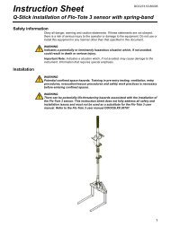
Assembly<br />
Assemble the extension tube and frame to the jack bar as shown in Figure 3.<br />
Note: The standard frame can be clamped from either end to define the direction that the sensor points.<br />
Determine the sensor direction, then clamp the frame.<br />
Figure 3 Assemble components<br />
1 Pipe cap 4 Frame<br />
2 Setscrew 5 Clamp half, not threaded<br />
3 Clamp half, threaded 6 Clamp bolt, ¼–20 x 1 in. (4x)<br />
© Hach Company, 2007. All rights reserved. Printed in the U.S.A. Edition 1 December, 2007