Instruction Sheet - Temporary mount assembly for Flo-Dar - Hachflow
Instruction Sheet - Temporary mount assembly for Flo-Dar - Hachflow
Instruction Sheet - Temporary mount assembly for Flo-Dar - Hachflow

Create successful ePaper yourself
Turn your PDF publications into a flip-book with our unique Google optimized e-Paper software.
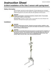
<strong>Temporary</strong> <strong>mount</strong> <strong>assembly</strong> <strong>for</strong> FLO-DAR sensor<br />
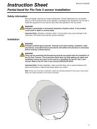
Install the temporary <strong>mount</strong> <strong>assembly</strong><br />
Important Note: Make sure the support structures will be able to handle the <strong>for</strong>ce of the<br />
jack (approximately 500 lb).<br />
The installation objectives, alignment and leveling <strong>for</strong> the sensor and sensor frame are the<br />
same as <strong>for</strong> the permanent <strong>mount</strong> described in the FLO-DAR Sensor User Manual<br />
(DOC026.53.00817 or DOC026.53.00786).<br />
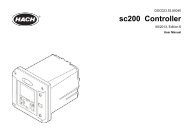
1. Install the jack bar <strong>assembly</strong> in the manhole. As a general rule, the jack bar should be<br />
approximately 20–24 inches above the crown (top) of the pipe. To prevent rotation<br />
along the axis of the jack bar <strong>assembly</strong> due to the weight of the sensor, install the jack<br />
bar <strong>assembly</strong> as parallel to the pipe as possible. A slight angle is required to use the<br />
optional retrieval pole and hook (See Figure 2).<br />
Compress the spring loaded foot approximately 32–38 mm (1.25–1.5 in.) or three to<br />
four cycles of the jack handle after initial contact with the wall.<br />
2. Assemble the extension pipe and frame to the jack bar as shown in Figure 3.<br />
3. Align and level the frame. Refer to the FLO-DAR Sensor user manual <strong>for</strong> specific<br />
dimension requirements based on sensor options. Review all safety precautions <strong>for</strong><br />
hazardous location installations.<br />
4. Once the temporary <strong>mount</strong> is positioned and leveled, tighten all bolts and setscrews.<br />
Figure 2 Installation in manhole<br />
1 Minimum angle to allow <strong>for</strong> sensor removal using retrieval pole and hook<br />
3