CPHS Phase 2 - Now SMS
CPHS Phase 2 - Now SMS
CPHS Phase 2 - Now SMS

You also want an ePaper? Increase the reach of your titles
YUMPU automatically turns print PDFs into web optimized ePapers that Google loves.
COMMON PCN HANDSET SPECIFICATION<br />
<strong>CPHS</strong> <strong>Phase</strong> 2<br />
Version Number: 4.2<br />
Date of Issue: 27 February 1997<br />
Document Reference: <strong>CPHS</strong>4_2.WW6<br />
The information contained in this specification is subject to the terms and conditions of the letter of agreement under which the specification is<br />
supplied to the Recipient's organisation.<br />
None of the information contained in this specification shall be disclosed outside the Recipient's own organisation without the prior written<br />
permission of a duly authorised representative of the Association of European PCN Operators (“The Association”), unless the terms of the letter of<br />
agreement permit such disclosure.<br />
No part of the specification may be reproduced, or transmitted in any way, or stored in any retrieval system, without the prior written approval of a<br />
duly authorised representative of The Association.<br />
Save as described above, none of the information contained in this document shall be used by the Recipient's organisation, nor disclosed to any third<br />
party without the prior written permission of a duly authorised representative of The Association.<br />
The Association or any of its members shall not be liable for any form of indirect consequential or special loss of profit, data, business or business<br />
opportunity howsoever occurring.<br />
The Recipient of this specification shall be responsible for ensuring that any item of work arising from the use of the specification shall not infringe<br />
any third party intellectual or industrial property rights. The Recipient shall indemnify The Association and each member of The Association against<br />
all costs, expenses and or liability arising in respect of any infringement or alleged infringement of a third party's intellectual or industrial property<br />
rights.<br />
Copyright (c) PCN Association {1997}<br />
All Rights Reserved<br />
Authors<br />
Name Organisation Fax<br />
Tim Haysom Orange PCS Ltd. +44 1454 618501<br />
Richard Williams Mercury One-2-One +44 181 214 2898<br />
Current Editor: Orange PCS Ltd.<br />
Copies of this specification are available in .PDF format (requires Adobe Acrobat reader) or on<br />
paper.<br />
For additional copies, please contact either author.
<strong>CPHS</strong> version 4.2 27 February 1997 Page 2 of 31<br />
COMMON PCN<br />
HANDSET SPECIFICATION<br />
( <strong>CPHS</strong> )<br />
Document History _______________________________________________________________ 3<br />
PART A - MARKETING REQUIREMENTS _________________________________________ 4<br />
A.1 INTRODUCTION AND HISTORY______________________________________________ 4<br />
A.2 OBJECTIVES_______________________________________________________________ 4<br />
A.3 Menu Display of Services______________________________________________________ 5<br />
A.4 Transportability of Services Information _________________________________________ 5<br />
A.5 INDICATORS_______________________________________________________________ 6<br />
A.5.1 General _________________________________________________________________________ 6<br />
A.5.2 Network Operator Name ___________________________________________________________ 6<br />
A.5.3 Home Country Roaming Indicator ___________________________________________________ 6<br />
A.5.4 Voice Message Waiting Indicator ____________________________________________________ 6<br />
A.5.5 Diverted Call Indicator ____________________________________________________________ 6<br />
A.5.6 Current Line Indicator_____________________________________________________________ 7<br />
A.6 ALTERNATE LINE SERVICE (ALS) ___________________________________________ 7<br />
A.7 EMERGENCY CALLING _____________________________________________________ 7<br />
PART B TECHNICAL REQUIREMENTS___________________________________________ 8<br />
B.1 SCOPE ____________________________________________________________________ 8<br />
B.2 SIM Requirements ___________________________________________________________ 8<br />
B.3 OVERVIEW OF ADDITIONAL REQUIREMENTS FOR <strong>CPHS</strong> _____________________ 8<br />
B.3.1 Enhanced SIM Requirements _______________________________________________________ 8<br />
B.3.1.1 <strong>CPHS</strong> Information______________________________________________________________________ 9<br />
B.3.2 Indicators_______________________________________________________________________ 10<br />
B.4 DETAILED TECHNICAL SPECIFICATIONS OF <strong>CPHS</strong> SPECIFIC FEATURES. ____ 10<br />
B.4.1 Service Accessibility ______________________________________________________________ 11<br />
B.4.1.1 Display in Idle Mode___________________________________________________________________ 11<br />
B.4.1.2 Network Operator Name ________________________________________________________________ 11<br />
B.4.2 Voice Message Waiting____________________________________________________________ 13<br />
B.4.2.1 Voice Message Waiting Indicator_________________________________________________________ 13<br />
B.4.2.2 Voice Message Retrieval and Indicator Clearing _____________________________________________ 14<br />
B.4.2.3 Voice Message Waiting Indicator Flags in the SIM ___________________________________________ 15<br />
B.4.3 Alternate Line Service ____________________________________________________________ 16<br />
B.4.4 MSISDN/ Line Identification in SIM ________________________________________________ 17<br />
B.4.5 Diverted Call Status Indicator______________________________________________________ 17<br />
B.4.6 Information Numbers_____________________________________________________________ 18<br />
B 4.6.1 Technical Specification_________________________________________________________________ 18<br />
B.4.6.2 DATA FIELD -6F 19: Information Numbers ________________________________________________ 20<br />
B.4.7 Customer Service Profile __________________________________________________________ 21
<strong>CPHS</strong> version 4.2 27 February 1997 Page 3 of 31<br />
B.4.7.1 Bit Significance of Customer Service Profile entries __________________________________________ 22<br />
B.4.8 Network and Service Provider Lock _________________________________________________ 26<br />
B.4.8.1 Introduction__________________________________________________________________________ 26<br />
B.4.8.2 Acronyms and Abbreviations ____________________________________________________________ 26<br />
B.4.8.3 Fundamental requirements for the Service Provider Lock Mechanism ____________________________ 26<br />
B.4.8.4 Operation of the SP Lock _______________________________________________________________ 27<br />
B.4.8.5 Unlocking The Subsidy Protection Lock ___________________________________________________ 27<br />
B.4.8.6 Requirements of the SIM _______________________________________________________________ 28<br />
B.4.8.7 Autolock Criteria______________________________________________________________________ 28<br />
B.4.8.8 Security handling details ________________________________________________________________ 28<br />
B.4.9 Language Reset __________________________________________________________________ 30<br />
B.4.10 Engineering Mode and SW version indication________________________________________ 30<br />
B.4.11 SIM Toolkit ____________________________________________________________________ 30<br />
Changes from version 3.0 to 3.1:<br />
MPC 2, 5rev2, 6rev1, 7, 8, 10<br />
U 1rev2, 2, 3, 4rev1, 6, 7rev1, 9<br />
MIC 1rev1, 3rev3, 4rev1<br />
Changes from version 3.1 to 3.2:<br />
MPC 12<br />
MIC 5, 6, 7, 8rev1<br />
Revised terms and conditions<br />
Changes from version 3.2 to 4.1<br />
Document History<br />
The document has been brought up to date and extended to introduce several new features:<br />
Information Numbers<br />
Shortform Operator Name String<br />
CSP Extensions<br />
Network and SP Lock<br />
Language reset<br />
Engineering mode and SW version restriction<br />
The Service String Table definition has been removed in favour of Information numbers.<br />
Changes from version 4.1 to 4.2<br />
Version 4.1 incorrectly referred to the Information numbers datafield as 6F1X or 6F18. This has<br />
been changed to 6F19.
<strong>CPHS</strong> version 4.2 27 February 1997 Page 4 of 31<br />
PART A - MARKETING REQUIREMENTS<br />
A.1 INTRODUCTION AND HISTORY<br />
COMMON PCN HANDSET SPECIFICATION<br />
In late 1989, three consortia were selected as providers of a new generation of Personal<br />
Communication services in the UK. These consortia formed an association, The Association of<br />
European PCN Operators (“The Association”), whose members as of January 1 st 1991 were<br />
Mercury Personal Communications, Microtel and Unitel.<br />
It was recognised and supported by The Association that the DCS 1800 standards defined by ETSI<br />
should form the basis upon which manufacturers should develop their technical specifications for<br />
handsets<br />
The DCS1800 specifications provide for a minimum level of functional commonality between<br />
handsets and are intended to ensure that all PCN handsets will be compatible with the network<br />
services offered by each PCN operator, and that a defined group of basic services will be supported<br />
in a consistent manner across each of the members of the association.<br />
In order to extend and promote DCS1800, the association agreed to produce a set of enhanced<br />
specifications known as the Common PCN handset Specification (<strong>CPHS</strong>) to provide significant<br />
benefits to manufacturers, end-users of PCN handsets and The Association.<br />
The <strong>CPHS</strong> specifications were the result of detailed discussions and agreement within The<br />
Association. It was the agreed intention of The Association that the PCN handsets that each<br />
operator individually purchased were compliant with these requirements<br />
During the initial launch of PCN networks in the UK, The Association sought to promote,<br />
encourage and endorse the use of <strong>CPHS</strong> handsets on their members networks.<br />
It was not the intention of The Association to specify in detail how handsets should be designed or<br />
operated, but to address those elements of functionality deemed necessary to meet the defined<br />
objectives.<br />
Issues such as handset size, weight, styling, individual choice of MMI, battery lifetime, etc. were left<br />
to the discretion of manufacturers seeking to establish differentiated positions in the developing<br />
PCN market.<br />
A.2 OBJECTIVES<br />
The objectives in proposing <strong>CPHS</strong> :<br />
a) The human interface shall be simple to use, intuitive, unambiguous and easy to learn. It<br />
shall be designed to enable the user to select handset features and network services with a<br />
minimum of education and selection delay.<br />
The number of keystrokes to access service and functions shall be minimised. As far as<br />
possible, the user shall not be required to memorise complex sequences of operations.
<strong>CPHS</strong> version 4.2 27 February 1997 Page 5 of 31<br />
b) Where possible, commonality of operation across GSM 900/1800/1900 networks should<br />
be utilised to simplify equipment design and provide economies of manufacturing scale.<br />
c) A minimum set of common services (“Core Services”) shall be supported by a majority of<br />
network operators.<br />
A customer using a <strong>CPHS</strong> handset shall be able to access any of the Core Services in a<br />
consistent manner irrespective of which network the individual is operating on.<br />
d) It shall be possible to define subsets of the minimum set of common services on a SIM to<br />
personalise a user's subscription.<br />
The use of this is optional by the ME. If this feature is implemented the technique detailed<br />
in <strong>CPHS</strong> should be used so that the user may retain this personalisation across any<br />
similarly featured <strong>CPHS</strong> handsets that accept compatible sized SIMs.<br />
A.3 Menu Display of Services<br />
The handset may optionally recover from the SIM Customer Service Profile the subset of services<br />
available through the user's subscription and display the appropriate menu options accessible<br />
through the single command interface.<br />
Additional items may also be included in these menus.<br />
If the handset does not use the Customer Service Profile to display a subset of Core Services it shall<br />
display all the Core Services, along with any additional items, in the menus accessible through the<br />
Single Command Interface.<br />
Where no Customer Service Profile is present on the SIM, the handset shall display all the Core<br />
Services along with any additional items.<br />
A.4 Transportability of Services Information<br />
It shall be possible for the service information specific to a user to be transportable between <strong>CPHS</strong><br />
handsets.<br />
This shall include:<br />
- User customised service strings.<br />
- Information related to a service (e.g. call forward number parameters where specified).<br />
Optionally, on suitably featured <strong>CPHS</strong> handsets it may include:<br />
- Customer Service Profile (relevant core services)
<strong>CPHS</strong> version 4.2 27 February 1997 Page 6 of 31<br />
A.5 INDICATORS<br />
A.5.1<br />
General<br />
Indicators are required in association with key network services to alert the user on current system<br />
status and provide supplementary information.<br />
Indicators shall be activated immediately upon receiving the appropriate activation signals from the<br />
network. No user actions should be required to activate an indicator.<br />
Some indicators prompt user actions. These indicators should be activated in a way that enables<br />
single command responses from the user.<br />
The indicators are listed below. These are not intended to be exhaustive and manufacturers may<br />
wish to offer handset solutions featuring additional indicators where these may prove of benefit to<br />
the PCN user.<br />
A.5.2<br />
Network Operator Name<br />
The network operator's name shall be retrieved from the SIM and should be the primary display<br />
whenever the phone is turned on, and is not in use for selection of a handset or network service.<br />
A.5.3<br />
Home Country Roaming Indicator<br />
An indicator (“ROAMING”) may be provided to tell the user that operation is not on the home<br />
network but service is currently being provided on an alternative network. This indicator shall be a<br />
function of the handset and normal network operation and shall not rely on any additional network<br />
messages for activation.<br />
A.5.4<br />
Voice Message Waiting Indicator<br />
<strong>CPHS</strong> defined standard formats for <strong>SMS</strong> messages advise the user that a voice message is awaiting<br />
retrieval from the user's voice mailbox. The handset may optionally use this standard format to<br />
distinguish between “voice” and “text” messages and provide separate indications according to the<br />
message types received.<br />
Additionally the handset shall, as a minimum, provide a message received indication per directory<br />
number where ALS is available.<br />
A.5.5<br />
Diverted Call Indicator<br />
An indication may be given to show that 'call forward unconditional' is active. If implemented this<br />
indication shall be displayed in idle mode.
<strong>CPHS</strong> version 4.2 27 February 1997 Page 7 of 31<br />
A.5.6<br />
Current Line Indicator<br />
An indication shall be given to the user of the currently selected line, or in the case of an MT call,<br />
the active line.<br />
A.6 ALTERNATE LINE SERVICE (ALS)<br />
ALS provides the MS with the capability of associating two alternate lines with one IMSI. A user<br />
will be able to make and receive calls on either line as desired and will be billed separately for calls<br />
on each line. Each line will be associated with a separate directory number (MSISDN) and separate<br />
subscription profile. The operation of ALS is described in B.4.3.<br />
Where ALS is available each directory number shall be treated separately from the point of view of<br />
basic and supplementary services, so that independent service sets may be assigned for each<br />
number. The exception is “Call Waiting”, which shall be treated as applying to both directory<br />
numbers if either or both numbers carry a subscription to this service. In such cases, the handset<br />
shall generate a call waiting indication if a call arrives whilst either line is engaged on another call.<br />
The user should be able to store and recover customised (alpha)numeric descriptions of the two<br />
lines. Where there is no user customised description, the handset shall display a default description<br />
of “Line 1” and “Line 2” for the two lines.<br />
The handset shall provide an indication of the line on which incoming and outgoing service is being<br />
requested by audible and/or visual differentiation.<br />
For outgoing calls, the handset shall enable the user to select the desired line via a single command<br />
interface.<br />
A.7 EMERGENCY CALLING<br />
As UK emergency services are accessed by dialling “999” (as well as “112”), UK PCN handsets<br />
shall enable both “999 SEND” and “112 SEND” calls to be processed without a valid SIM. If<br />
the handset is locked by use of a PIN, entering “999 SEND” or “112 SEND” must activate<br />
emergency calling. As a consequence PIN values beginning 112 or 999 shall not be presented by<br />
the ME to the SIM.<br />
If the SIM is removed during an emergency call, the call shall continue.<br />
Enhanced MMI for emergency calling over and above this minimum requirement may be provided.
<strong>CPHS</strong> version 4.2 27 February 1997 Page 8 of 31<br />
PART B<br />
TECHNICAL REQUIREMENTS<br />
B.1 SCOPE<br />
This part defines the common, minimum, set of technical requirements applicable to <strong>CPHS</strong> Mobile<br />
Stations.<br />
These requirements are necessary:-<br />
a) To ensure that there is universal technical support for a minimum agreed set of features<br />
which will function on all GSM 900/ 1800 & 1900 networks.<br />
b) To clarify relevant areas of potential ambiguity or omissions in the GSM or DCS1800<br />
specifications.<br />
c) To indicate clearly those areas of difference between the GSM and DCS1800 specifications<br />
in order to help MS manufacturers understand changes.<br />
d) To indicate additional requirements to GSM and DCS1800 for <strong>CPHS</strong>.<br />
B.2 SIM Requirements<br />
SIM fields relevant to the operation of DCS1800 are contained in a DCS1800 application directory.<br />
This is an alias directory of the GSM application directory to ensure compatibility when SIMs are<br />
transferred between 900, 1800 & 1900 MHz equipment. This is described in GSM 11.11.<br />
B.3 OVERVIEW OF ADDITIONAL REQUIREMENTS FOR <strong>CPHS</strong><br />
These requirements are additional to the GSM 900 and DCS1800 recommendations. They apply to<br />
all products which are to be compliant with the <strong>CPHS</strong> specification.<br />
B.3.1<br />
Enhanced SIM Requirements<br />
In addition to those SIM storage fields previously defined in DCS1800 to support existing MS<br />
features and services, the Association has defined the following fields :-<br />
1) Call Forwarding flag (mandatory)<br />
2) Voice message waiting flag (mandatory)<br />
3) PLMN operator name (mandatory)<br />
4) Customer Service Profile (CSP) (optional)<br />
5) <strong>CPHS</strong> Information (mandatory)<br />
6) Mailbox Numbers (optional)<br />
7) Information Numbers (optional)<br />
Full details of the operation of these features is contained in section B.4, “Detailed technical<br />
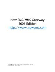
specifications of <strong>CPHS</strong> features”. The directory structure of a <strong>CPHS</strong> SIM is shown in figure A.1.<br />
The series of identifiers 6F 1X is reserved within GSM for “administrative use”.
<strong>CPHS</strong> version 4.2 27 February 1997 Page 9 of 31<br />
Root Directory<br />
3F 00<br />
GSM Directory<br />
7F 20/21<br />
Voice<br />
message<br />
waiting<br />
6F11<br />
Service<br />
String<br />
Table<br />
6F12<br />
Reserved<br />
for phase<br />
1 <strong>CPHS</strong><br />
Call<br />
forward<br />
flags<br />
6F13<br />
Operator<br />
name<br />
string<br />
6F14<br />
Customer<br />
service<br />
profile<br />
6F15<br />
<strong>CPHS</strong><br />
Info.<br />
6F16<br />
Mailbox<br />
numbers<br />
6F17<br />
Operator<br />
name<br />
shortform<br />
6F18<br />
Info.<br />
Numbers<br />
6F19<br />
Figure 1 - <strong>CPHS</strong> specific datafields (see also GSM 11.11)<br />
B.3.1.1<strong>CPHS</strong> Information<br />
The <strong>CPHS</strong> Information data-field is needed to contain the <strong>CPHS</strong> phase of the SIM and to indicate<br />
which optional data-fields are present in the SIM.<br />
DATA FIELD - 6F 16: <strong>CPHS</strong> INFORMATION<br />
Purpose :<br />
This data-field contains the <strong>CPHS</strong> phase of the SIM as well as the <strong>CPHS</strong> Service Table indicating<br />
which of the <strong>CPHS</strong> optional data-fields are present in the SIM card. The ME should read this datafield<br />
as part of the SIM initialisation procedure (see GSM 11.11) and it should only subsequently<br />
attempt to read or update an optional data-field if the data-field is indicated as being both allocated<br />
and activated in the <strong>CPHS</strong> Service Table.<br />
Identifier: '6F16 Structure: transparent Optional<br />
File size: n bytes<br />
Update activity: low<br />
Access Conditions:<br />
READ<br />
UPDATE<br />
INVALIDATE<br />
REHABILITATE<br />
CHV1<br />
ADM<br />
ADM<br />
ADM<br />
Bytes Description M/O Length<br />
1 <strong>CPHS</strong> <strong>Phase</strong> M 1<br />
2-3 <strong>CPHS</strong> Service Table M 2<br />
4-n RFU O n-3
<strong>CPHS</strong> version 4.2 27 February 1997 Page 10 of 31<br />
Structure of the data field:<br />
Byte 1: <strong>CPHS</strong> phase, coded as:<br />
01 phase 1<br />
02 phase 2<br />
etc.<br />
Byte 2: <strong>CPHS</strong> Service Table<br />
b8 b7 b6 b5 b4 b3 b2 b1<br />
OpName Shortform<br />
(<strong>Phase</strong> 2 only)<br />
Mailbox Numbers<br />
(All phases)<br />
SST<br />
(<strong>Phase</strong> 1 only)<br />
CSP<br />
(All phases)<br />
Activated Allocated Activated Allocated Activated Allocated Activated Allocated<br />
Byte 3: <strong>CPHS</strong> Service Table continued<br />
b8 b7 b6 b5 b4 b3 b2 b1<br />
RFU RFU RFU Information numbers<br />
(<strong>Phase</strong> 2 only<br />
0 0 0 0 0 0 Activated Allocated<br />
Service Allocated is indicated by as ‘1’ in the lower bit of each service pair<br />
Service Activated is indicated by as ‘1’ in the upper bit of each service pair<br />
Service Not Allocated is indicated by as ‘1’ in the lower bit of each service pair<br />
If the service is not allocated then the state of the activated bit has no meaning<br />
Future optional services may be defined and shall be coded onto subsequent bytes<br />
B.3.2 Indicators<br />
To support the Core Services (defined in A.3.2), the following display indicators (and the<br />
associated SIM datafields) are needed.<br />
- Network Operator Name (mandatory)<br />
- Home Country Roaming (optional)<br />
- Voice Message Waiting (mandatory)<br />
- Diverted Calls (optional)<br />
B.4 DETAILED TECHNICAL SPECIFICATIONS OF <strong>CPHS</strong> SPECIFIC FEATURES.<br />
This section defines details of the technical requirements (additional to the DCS1800<br />
recommendations) which also apply to the <strong>CPHS</strong> products.
<strong>CPHS</strong> version 4.2 27 February 1997 Page 11 of 31<br />
B.4.1<br />
Service Accessibility<br />
B.4.1.1Display in Idle Mode<br />
When the MS is in idle mode and registered with a PLMN (i.e. a location update has been<br />
accepted), the MS shall display the following:<br />
Selection<br />
Method<br />
Home PLMN<br />
Roaming<br />
within Home<br />
Country<br />
Roaming<br />
outside Home<br />
Country<br />
Automatic Name HCR MCC/MNC<br />
Manual Name MCC/MNC MCC/MNC<br />
Where<br />
Name = Network operator name string as in section B.4.1.3<br />
HCR = A Home Country Roaming Indicator (“ROAMING”)<br />
may be displayed.<br />
MCC = Mobile Country Code<br />
MNC = Mobile Network Code<br />
Notes:-<br />
1 It is allowable to temporarily remove the operator name to display other ME or system<br />
messages to the user.<br />
2 The decision on whether roaming is within or outside the home country is made on the basis<br />
of the MCC of the selected PLMN.<br />
3 Where MCC/MNC is shown in the table this is the minimum display acceptable. Additional<br />
procedures may be supported by a manufacturer whereby country and operator names can<br />
be displayed. It is preferable to use the latest version of the MoU list of operator names<br />
(SE.13) to display the applicable roaming operator.<br />
B.4.1.2Network Operator Name<br />
Under some circumstances it is desired to show the PLMN operator's name on the MS display.<br />
The name of the operator will be contained on the SIM issued to a subscriber in one or both of the<br />
<strong>CPHS</strong> datafields below.<br />
The field structures to be used for the storage of these name strings are as follows:-<br />
The ME may choose which name to use, dependent upon its display size and how well it can format<br />
the name.
<strong>CPHS</strong> version 4.2 27 February 1997 Page 12 of 31<br />
DATA FIELD - 6F 14: OPERATOR NAME STRING<br />
Purpose :<br />
This data field contains the name of the PLMN operator who issued the SIM. This is read by the<br />
ME for display in idle mode.<br />
Identifier: '6F14' Structure: transparent Optional<br />
Record length: n bytes<br />
Update activity: low<br />
Access Conditions:<br />
READ<br />
UPDATE<br />
INVALIDATE<br />
REHABILITATE<br />
CHV1<br />
ADM<br />
ADM<br />
ADM<br />
Bytes Description M/ Length<br />
O<br />
1 to n PLMN name M n bytes<br />
Coding:<br />
The PLMN name shall be coded in default 7 bit alphabet (see GSM 03.40) with b8 set to 0. Unused<br />
bytes shall be set to ‘FF’<br />
DATA FIELD - 6F 18: OPERATOR NAME SHORTFORM<br />
Purpose :<br />
This data field contains a shortform of the name of the PLMN operator who issued the SIM. This is<br />
read by the ME for display in idle mode and is used instead of the Operator Name String by the ME<br />
if its display cannot accommodate the complete Operator Name String.<br />
Identifier: '6F18' Structure: transparent Optional<br />
Record length: 10 bytes<br />
Update activity: low<br />
Access Conditions:<br />
READ<br />
UPDATE<br />
INVALIDATE<br />
REHABILITATE<br />
CHV1<br />
ADM<br />
ADM<br />
ADM<br />
Bytes Description M/ Length<br />
O<br />
1 to 10 Operator Name Shortform M 10 bytes<br />
Coding:<br />
The Operator Name Shortform shall be coded in default 7 bit alphabet (see GSM 03.40) with b8 set<br />
to 0. Unused bytes shall be set to ‘FF’
<strong>CPHS</strong> version 4.2 27 February 1997 Page 13 of 31<br />
B.4.2<br />
Voice Message Waiting<br />
B.4.2.1Voice Message Waiting Indicator<br />
The GSM short message present indicator may be enhanced in order to distinguish between voice<br />
messages and normal text short messages. An agreed voice message format will be used by the<br />
network operators.<br />
A handset manufacturer may use this format in order to provide a separate Voice Message<br />
Indicator.<br />
The basic principle is that the short message originating entity address (associated with the Voice<br />
Messaging Centre), which is not used by the network, is used to select the handset indicator and<br />
control its condition (on or off).<br />
The user data transported in a voice message waiting message shall consist of either:<br />
(i)<br />
a single space (character coded as 0100000 b7..b1 in the default alphabet in GSM<br />
03.40), or;<br />
(ii) free-format text (coded in the default alphabet specified in GSM 03.40).<br />
Where the user data consists only of a single space, the short message shall not be stored on the<br />
SIM but shall be used to select and control the indicator. If more user data is present the short<br />
message shall be used to select and control the indicator and shall be stored on the SIM as normal.<br />
The indicator messages and the actions to be made on them shall be identified from the originating<br />
SME address. For Short Message, mobile terminated, the originating SME address is contained in<br />
the TS-Originating-Address parameter of the TS-Deliver primitive, and is transferred in the TP-<br />
Originating-Address element of the <strong>SMS</strong>-Deliver TPDU.<br />
Beyond the specification of the originating SME address to be used for indicator short messages,<br />
the procedures for handling such messages in the MS, and for supporting such indicators from the<br />
network, are not specified.<br />
The originating SME address field shall be coded as follows:<br />
Octet 1<br />
Octet 2<br />
Address-Length (coded in binary)<br />
constant value 00000100 (note 1)<br />
Type-of-Address<br />
bit 8 always set to 1 1<br />
bits 7..5 type of number: 101 (alphanumeric)<br />
bits 4..1 numbering plan id: 0000<br />
Octets 3-4 Address Value (note 2)<br />
Character 1<br />
bit 1 set/clear indicator<br />
0 clear<br />
1 set
<strong>CPHS</strong> version 4.2 27 February 1997 Page 14 of 31<br />
Notes:<br />
bits 4..2 type of indicator<br />
000 voice message waiting indicator<br />
bits 7..5<br />
001 constant value<br />
Character 2<br />
bit 1 indicator identifier<br />
0 indicator 1<br />
1 indicator 2<br />
bits 7..2<br />
000000 constant value<br />
(1) Octet 1 has the value 4 (decimal) indicating that 4 semi-octets are used for the address-value<br />
part of the address field.<br />
(2) The alphanumeric character definitions and the packing of characters into octets in the<br />
Address field are as defined in GSM Rec. 03.40 Annex 2. Characters 1 and 2 are 7 bits in<br />
length.<br />
(3) Using this scheme the handset cannot differentiate between voice messaging centres.<br />
(4) This scheme gives independent control of indicators 1 and 2. For <strong>CPHS</strong> handsets indicator 1<br />
is associated with line 1 and indicator 2 is associated with line 2.<br />
(5) The <strong>CPHS</strong> method of coding a voice message may be used in conjunction with the two<br />
GSM phase 2+ standardised methods using TP-DCS or TP-UD. These methods are described in<br />
GSM 03.38 and 03.40 V5+.<br />
B.4.2.2Voice Message Retrieval and Indicator Clearing<br />
A voice message shall be retrieved using the procedure appropriate for that voice message centre.<br />
The dialling number of the voice mailbox can be found by the ME in the Mailbox Numbers datafield.<br />
The structure of this data-field is similar to the Abbreviated Dialling data-field so that<br />
different numbers can be stored against different bearer capabilities:<br />
Data field 6F 17: Mailbox Numbers<br />
Purpose:<br />
To store dialling numbers to be used for message retrieval from<br />
mailboxes. The Capability/Configuration Identification byte indicates<br />
the bearer capability required to access that mailbox. The alpha-tags<br />
serve no essential purpose but may be used by the MMI to indicate<br />
mailbox types (i.e. voice, fax, etc.).
<strong>CPHS</strong> version 4.2 27 February 1997 Page 15 of 31<br />
Identifier: '6F17' Structure: linear fixed Optional<br />
Record length: X+14 bytes<br />
Update activity: low<br />
Access Conditions:<br />
READ<br />
UPDATE<br />
INVALIDATE<br />
REHABILITATE<br />
CHV1<br />
CHV1<br />
ADM<br />
ADM<br />
Bytes Description M/ Length<br />
O<br />
1 to X Alpha Identifier O X bytes<br />
X+1 Length of BCD number contents M 1 byte<br />
X+2 TON and NPI M 1 byte<br />
X+3 to X+12 Mailbox Number String M 10 bytes<br />
X+13 Capability/Configuration Identifier M 1 byte<br />
X+14 Extension1 Record Identifier M 1 byte<br />
For contents and coding of all data items see the respective data items of EF ADN in GSM 11.11.<br />
NOTE 1:<br />
The value of X (the number of bytes in the alpha-identifier) may be<br />
different to the length denoted X in EF ADN in GSM 11.11.<br />
NOTE 2:<br />
Optionally, if the ME does not support capabilities configuration<br />
identifiers, then the following convention shall be used:<br />
Record 1 Line 1 mailbox<br />
Record 2 Line 2 mailbox<br />
Record 3 Data mailbox<br />
Record 4 Fax mailbox<br />
Message waiting indicator clearing can be achieved using the defined short message format or the<br />
handset may offer a means of clearing the indicator manually.<br />
B.4.2.3Voice Message Waiting Indicator Flags in the SIM<br />
<strong>CPHS</strong> has defined flags in the SIM to store the state of these indicators.<br />
The contents of these flags should be read on power up and used to set the indicators to the correct<br />
state.<br />
The following is the definition (in the manner of GSM 11.11) of this field:-<br />
The ME shall update the SIM flags immediately it detects a change in their status. This is to ensure<br />
that information is not lost, should power be cut to the ME.<br />
DATA FIELD -6F 11: Voice message waiting flag<br />
Purpose :<br />
Storing the status of indicators that define whether a voice message is waiting. This status is used to<br />
set the message waiting indicator after re-activation of the handset. The use of this data field is<br />
optional at the discretion of the manufacturer.
<strong>CPHS</strong> version 4.2 27 February 1997 Page 16 of 31<br />
Identifier: '6F11' Structure: transparent Optional<br />
Record length: n bytes<br />
Update activity: low<br />
Access Conditions:<br />
READ<br />
UPDATE<br />
INVALIDATE<br />
REHABILITATE<br />
CHV1<br />
CHV1<br />
ADM<br />
ADM<br />
Bytes Description M/ Length<br />
O<br />
1 Voice Message Waiting Indicator flags M 1<br />
2 Fax / Data Message Waiting Indicator flags O 1<br />
3-n RFU O n-2<br />
Structure of the Message Waiting flags<br />
If a message is waiting, the nibble should contain A (HEX).<br />
If no message is waiting the nibble should contain 5 (HEX)<br />
Byte 1 Nibble 1 is used to store the status of the 'Line 1' message and nibble 2 that of 'Line 2'.<br />
Byte 2 Nibble 1 is used to store the status of the 'Fax' message and nibble 2 that of 'data' status.<br />
B.4.3<br />
Alternate Line Service<br />
The principle of network operation is to associate a series of MSISDNs against a single IMSI. An<br />
additional requirement to the GSM recommendations is the definition of an additional Teleservice<br />
and Bearer capability - See Appendix 2.<br />
Within GSM each MSISDN can be associated with a different bearer capability to facilitate service<br />
interworking with a PSTN. For the purposes of providing dual speech services <strong>CPHS</strong> defines a<br />
second teleservice called 'Auxiliary Speech'.<br />
The ISDN number used to route an incoming call determines whether the call is associated with the<br />
speech or auxiliary speech bearer capability. The translation from MSISDN to speech/auxiliary<br />
speech is done at the terminating MSC and is conveyed to the MS during call set up by means of<br />
the bearer capability information element. This shall be used by the handset to provide an indication<br />
of which line is being called, either by different ring tones and/or a clear display message such as<br />
“Line 2”.<br />
For outgoing calls the MS manufacturer must provide a means of selecting Line 1 or Line 2. The<br />
MS then selects the appropriate teleservice, either 'Telephony' or 'Auxiliary Telephony', and the<br />
appropriate bearer capability (speech or auxiliary speech respectively), dependent on whether Line<br />
1 or Line 2 is selected.<br />
The network will associate both of these teleservices with speech and associate the appropriate<br />
MSISDN with the call. It will itemise them separately on the billing records, allowing post<br />
processing into two separate bills.<br />
Handset procedures which select the Line number implicitly select the corresponding<br />
Supplementary Service (SS) operations mode so that apply to the selected line. This allows, for<br />
example, barring and diverting of calls to be performed differently for each MSISDN number.
<strong>CPHS</strong> version 4.2 27 February 1997 Page 17 of 31<br />
Where a SS operation is performed and no teleservice supplementary information byte is explicitly<br />
entered, then the MS will insert the correct teleservice (either Telephony or Auxiliary Telephony)<br />
depending on the line number currently selected.<br />
Whenever a customer's MSISDN is displayed, the MSISDN of the active line shall be used.<br />
Only one incoming call at a time is set up to the MS. Initiating the answer sequence (by pressing the<br />
'send' key or its equivalent) will automatically answer the incoming call irrespective of which line<br />
has been selected.<br />
For Mobile terminated calls, if Calling Number Identification is activated, the Calling Number<br />
Identification information must be displayed with the active line number during call ringing.<br />
B.4.4<br />
MSISDN/ Line Identification in SIM<br />
The MSISDN/Line Identification feature shall be provided through the use of the MSISDN datafield.<br />
When appropriate the ME displays the MSISDN of the active line. The MSISDN for a given line is<br />
distinguished using the Capabilities/Configuration byte included in the record. The alpha-tag in the<br />
record will contain a description of the line and its use by the ME is optional.<br />
Optionally, if the ME does not support capabilities configuration identifiers, then the following<br />
convention shall be used:<br />
Record 1 Line 1 MSISDN<br />
Record 2 Line 2 MSISDN<br />
Record 3 Data MSISDN<br />
Record 4 Fax MSISDN<br />
It is left to the manufacturer to provide a means for the user to personalise/interrogate this field.<br />
B.4.5<br />
Diverted Call Status Indicator<br />
Whilst it is recognised that the status of the service in the network can only accurately be obtained<br />
by interrogation of the call forwarding Supplementary Service, an indication can be provided on the<br />
handset based on the last operation performed on that supplementary service.<br />
An MS supporting this feature shall therefore set the Call Forward Unconditional indicator when<br />
the network confirms user execution of the “set call forward unconditional”. It should be cleared<br />
when the network confirms execution of the “clear call forward unconditional” or “clear all call<br />
forward options”.<br />
To support ALS it is necessary to store the current state of the call forward unconditional options<br />
for both line 1 and line 2. Whether both indications are displayed simultaneously, or only the one<br />
corresponding to the currently selected handset mode (either line 1 or line 2) is a manufacturers<br />
option.<br />
In order to retain the status of the indicators during periods when the equipment is turned off,<br />
(and/or the battery removed) <strong>CPHS</strong> has assigned flags for this purpose in the SIM.
<strong>CPHS</strong> version 4.2 27 February 1997 Page 18 of 31<br />
For an MS supporting this feature the indicators must be set to match the stored status on powering<br />
up the MS, or when a network interrogation returns status information of this service.<br />
The ME shall update the SIM flags immediately it detects a change in their status. This is to ensure<br />
that information is not lost, should power be cut to the ME.<br />
The following wording (in the manner of 11.11) defines these fields:-<br />
DATA FIELD -6F 13: Call forwarding flags<br />
Purpose :<br />
Storing the status of a MS flag that records whether or not call forward unconditional is active. The<br />
status may be used to set the forwarding indicators after re-activation of the handset.<br />
Identifier: '6F13' Structure: transparent Optional<br />
Record length: n bytes<br />
Update activity: low<br />
Access Conditions:<br />
READ<br />
UPDATE<br />
INVALIDATE<br />
REHABILITATE<br />
CHV1<br />
CHV1<br />
ADM<br />
ADM<br />
Structure of the data field:<br />
Bytes Description M/ Length<br />
O<br />
1 Voice Call forward unconditional flags M 1<br />
2 Data/fax call forward unconditional flags O 1<br />
3-n RFU O n-2<br />
If call forwarding unconditional is active the nibble should contain A (HEX).<br />
If no call forwarding message is waiting the nibble should contain 5 (HEX)<br />
Byte 1 Nibble 1 is used to indicate the “call forward unconditional” status for 'line 1' and nibble 2<br />
for 'line 2'.<br />
Byte 2 Nibble 1 is used to indicate the “call forward unconditional” status for ‘fax’ (MMI service<br />
code 13 from GSM 02.30) and nibble 2 that of 'data'. (comment which data??)<br />
B.4.6 Information Numbers<br />
The Information Numbers data-field is optional in the SIM. The Information Numbers information<br />
shall only be presented to the user when the <strong>CPHS</strong>-defined Customer Service Profile (CSP) datafield<br />
contains a Service Group Code (byte A) of D5 hex, with an associated byte B of FF hex.<br />
The ME shall support user access to the “Information Number” data field stored on the SIM.<br />
The MMI shall allow structured hierarchical access to entries within the field. An indication shall<br />
be made to the user that marked entries will be charged as premium rate services.<br />
B 4.6.1Technical Specification
<strong>CPHS</strong> version 4.2 27 February 1997 Page 19 of 31<br />
This data-field is written to the card during preparation and contains a directory of useful numbers<br />
for information services with user friendly multilevel indexing for number selection. Each record is<br />
either an alphatagged number entry or an index name with a group of number entries associated<br />
with it.<br />
The indexing is multilevel as illustrated below:<br />
Index<br />
level<br />
1<br />
TRAVEL WEATHER ENTERTAINMENT<br />
Index<br />
level<br />
2<br />
TAXIS AIRPORTS North South Ticketmaster<br />
323 597 562<br />
Index<br />
level<br />
3<br />
Computercabs Dial-a-cab Heathrow Gatwick<br />
111 132 345 651<br />
Figure 2<br />
Multilevel Index Structure for Information Numbers<br />
This is coded into the data-field by placing an index level identifier into each record, as shown<br />
schematically in the table below.<br />
Index Level Example Alpha-tag Example Numbers<br />
1 TRAVEL null<br />
2 TAXIS null<br />
3 Computercabs 111<br />
3 Dial-a-cab 132<br />
2 AIRPORTS null<br />
3 Heathrow 345<br />
3 Gatwick 651<br />
1 WEATHER null<br />
2 North 323<br />
2 South 597<br />
1 ENTERTAINMENT null<br />
2 Ticketmaster 562<br />
Simplified Representation of Information Numbers Data-field<br />
Index Name entries are distinguished from Number Entries by having null number values (i.e.<br />
length byte and Type of Number bytes set to FF). To speed searching through the table for options<br />
to display to the user, the number section of an Index Name entry may optionally contain a pointer<br />
to the next entry of the same index level. This feature will not be programmed into the SIM's at<br />
launch although it may be provided in later issues of SIM's.<br />
In order to retain future flexibility and yet minimize memory space used in the SIM in the short<br />
term, neither the alpha-tag nor the number section of the records are given a fixed length. It is<br />
anticipated that three-digit numbers shall be put into the data-field and a number translation will<br />
occur within the network.<br />
There shall be both a Premium Service Indicator and a Network Specific Indicator flag contained in<br />
each entry. The Premium Service Indicator shows whether the call will be charged at a premium
<strong>CPHS</strong> version 4.2 27 February 1997 Page 20 of 31<br />
rate and this should be indicated to the customer prior to selection. The Network Specific Indicator<br />
marks a network specific entry that should not be presented to the user when the MS roams onto<br />
other networks.<br />
Information Numbers only apply to speech call and have no line significance for the Alternate Line<br />
Service (ALS). Entries shall be selectable independently of whether the ME is in line 1 or line 2<br />
mode. The bearer capability for the call requested from the network shall be taken from the current<br />
mode of the handset.<br />
The Update Security policy for the data-field is set to “CHV1” to enable remote SIM<br />
personalization of the data-field in later phases of the network. This would be achieved by inserting<br />
entries into completely null records left in the middle of data-fields. The ME shall not provide<br />
mechanisms for altering the alphatags and associated telephone numbers.<br />
B.4.6.2DATA FIELD -6F 19: Information Numbers<br />
If the ME cannot find Identifier ‘6F19’, it shall attempt to read identifier ‘EA01’ which may contain<br />
Information Numbers in older SIM cards.<br />
Identifier: '6F19’ Structure: linear fixed Optional<br />
Record length: 5+Y+Z bytes<br />
Update activity: low<br />
Access Conditions:<br />
READ<br />
UPDATE<br />
INVALIDATE<br />
REHABILITATE<br />
CHV1<br />
CHV1<br />
ADM<br />
ADM<br />
Bytes Description M/ Length<br />
O<br />
1 Alpha length M 1 byte<br />
2 Entry Status (defined below) M 1 byte<br />
3 to Y+2 Alpha Identifier O Y bytes<br />
Y+3 Length of called party BCD number (04.08) M 1 byte<br />
Y+4 TON and NPI M 1 byte<br />
Y+5 to Digits section M Z bytes<br />
Y+Z+4<br />
Y+Z+5 Extension1 Record Identifier M 1 byte<br />
For the filled records, the above bytes shall be coded in the following way.<br />
Alpha length Number of bytes in the alpha-tag section of the record. This byte has the<br />
same value for each filled entry of the data-field.<br />
Entry Status b8 b7 b6 b5 b4 b3 b2 b1<br />
1 1 Network<br />
Specific<br />
Indicator<br />
Premium<br />
Service<br />
Indicator<br />
Index Level Identifier<br />
Bits 1 to 4 represent the Index Level Identifier for the entry. All level 1<br />
entries are initially displayed by the ME to the user upon selection of<br />
Information Numbers featured by the user. Entries with a higher index<br />
level are only displayed to the user when the preceding entry with a<br />
lower index level has been selected.<br />
The coding is as follows:
<strong>CPHS</strong> version 4.2 27 February 1997 Page 21 of 31<br />
bit 4 bit 1<br />
0 0 0 1 Index level 1<br />
0 0 1 0 Index level 2<br />
0 0 1 1 Index level 3<br />
etc.<br />
The Premium Service indicator is set to “1” when the entry, or whole<br />
group of entries associated with the index name, are charged at a<br />
premium rate. The ME should provide an indication of a Premium<br />
Service entry prior to number selection.<br />
Alpha-tag<br />
Length of called<br />
party BCD<br />
number contents<br />
Type of Number,<br />
etc.<br />
Digits section<br />
The Network Specific Indicator is set to “1” for entries whose associated<br />
numbers are specific to the HPLMN and therefore should not be<br />
selectable when the handset is roaming on a VPLMN. It is applicable to<br />
index names and number entries.<br />
The alpha-tag is coded in the short message alphabet given in GSM<br />
03.40, with bit 8 set to zero. The number of bytes in this section (Y) is<br />
given by the Alpha length.<br />
For Number Entries, this byte is equal to the number of significant bytes<br />
in the digits section (i.e., non-FF) plus the type of number byte. For<br />
Index Names, this byte is set to FF.<br />
This byte is as specified in octet 3 of the called party BCD number<br />
information element of GSM 04.08 This byte is only used for number<br />
entries and not index names. It is set to FF for all index name entries.<br />
The number of bytes in this section can be deduced from the record<br />
length (given in Get Response after selection of the data-field) and the<br />
value of Y as follows:<br />
Z = Record Length - Y - 5<br />
For Number Entries, the digits of the number are coded as BCD with<br />
digit 1 in bits 1 to 4 of byte g, digit 2 in bits 5 to 8 of byte g, digit 3<br />
coded in bits 1 to 4 of byte g+1, etc. Unused nibbles at the end of the<br />
section shall have all their bits set to all 1.<br />
Extension1<br />
Record Identifier<br />
If the record contains an index name, the first byte may contain either the<br />
absolute record number of the next entry in the absolute record number<br />
of the next entry in the Information Numbers data-field which has the<br />
same index level, or a value of FF. All of the other bytes in this section<br />
are set to FF.<br />
This is coded in binary and gives the associated record number in<br />
datafield 6F 3E. For records containing Index names, this byte is set for<br />
FF.<br />
Null records can be located between filled records, and are coded with all<br />
bytes in the new record set to FF. The ME shall ignore such null records<br />
and look at the following record for the next significant entry.<br />
B.4.7<br />
Customer Service Profile
<strong>CPHS</strong> version 4.2 27 February 1997 Page 22 of 31<br />
The Customer Service Profile (CSP) is a list on the SIM which indicates the services which are<br />
customer accessible using the single command interface. Each of these services has a related bit<br />
within the CSP. Each of these CSP bits allows the ME to present only the menu item(s) relevant to<br />
that service to the user.<br />
The use of the CSP to control the MMI is in addition to the MMI procedures defined in GSM 02.30.<br />
The ME should not use the CSP to prevent access to services by these procedures.<br />
B.4.7.1Bit Significance of Customer Service Profile entries<br />
An entry in the Customer Service Profile consists of two bytes. The first byte is a Service Group<br />
Code which is used to associate related services together within the CSP.<br />
Each bit of the second byte has specific significance. A bit set to '1' indicates that the service is<br />
customer accessible via the single command interface, a bit set to '0' indicates that it is not.<br />
Unused bits are set to '0'<br />
The following table shows the bit significance for each Service Group code:-<br />
Byte A<br />
<br />
Byte B<br />
<br />
Service<br />
Group<br />
Code<br />
Service Bit 8 Bit 7 Bit 6 Bit 5 Bit 4 Bit 3 Bit 2 Bit<br />
1<br />
01 Call offering CFU CFB CFNRy CFNRc CT<br />
02 Call<br />
BOAC BOIC BOIC BAIC<br />
exHC<br />
Restriction<br />
03 Other Supp MPTY CUG AoC Pref.<br />
CUG<br />
Services<br />
04 Call<br />
HOLD CW CCBS User User<br />
Signalling<br />
Completion<br />
05 Teleservices SM/MT SM/MO SM/CB Reply<br />
06 <strong>CPHS</strong><br />
Teleservices<br />
07 <strong>CPHS</strong><br />
Features<br />
08 Number<br />
Identif.<br />
09 <strong>Phase</strong> 2+<br />
services<br />
C0<br />
D5<br />
ValueAdded<br />
Services<br />
Information<br />
Numbers<br />
ALS<br />
path<br />
BIC Roam<br />
CUG OA<br />
Del. Conf<br />
Protocol<br />
ID<br />
Validity<br />
Period<br />
Reserved<br />
(SST in<br />
phase 1<br />
<strong>CPHS</strong>)<br />
CLIP Reserved CoLR CoLP MCI CLI<br />
send<br />
GPRS HSCSD Voice<br />
Group call<br />
PLMN<br />
MODE<br />
VPS<br />
The service abbreviations used above are:<br />
SM/MO<br />
PAGING<br />
Voice<br />
Broadcast<br />
Service<br />
SM/MO<br />
EMAIL<br />
Multiple<br />
Subscriber<br />
Profile<br />
Information Numbers<br />
Multiple<br />
Band<br />
CLI<br />
block<br />
Fax Data Reserved Lang<br />
uage<br />
CFU Call Forwarding Unconditional SM/MO Short Message - Mobile<br />
Originated
<strong>CPHS</strong> version 4.2 27 February 1997 Page 23 of 31<br />
CFB Call Forwarding On User Busy SM/CB Short Message - Cell<br />
Broadcast<br />
CFNRy Call Forwarding on No Reply Reply path Restricts menu options for the<br />
ability to set reply path active<br />
on outgoing Short Messages<br />
CFNRc Call Forwarding On User Not Del. Conf <strong>SMS</strong> Delivery Confirmation<br />
Reachable<br />
CT Call Transfer ALS Alternate Line Service<br />
BOAC Barring of All Outgoing Calls CLIP Calling Line Identification<br />
Presentation<br />
BOIC Barring of Outgoing CLIR Calling Line Identification<br />
BOICexHC<br />
BAIC<br />
International Calls<br />
Barring of Outgoing<br />
International Calls except those<br />
directed to the Home PLMN<br />
country<br />
Barring of All Incoming Calls<br />
when Roaming Outside the<br />
Home PLMN country<br />
CoLP<br />
CoLR<br />
Restriction<br />
Connected Line Identification<br />
Presentation<br />
Connected Line Identification<br />
Restriction<br />
MPTY Multi-Party Service MCI Malicious Call Indicator<br />
CUG Closed User Group CLI block CLI per call mode - default<br />
send CLI - menu to block CLI<br />
AoC Advice Of Charge CLI send CLI per call mode - default<br />
block CLI - menu to send CLI<br />
Pref. CUG Preferential CUG PLMN<br />
mode<br />
Restriction of menu options<br />
for manual PLMN selection<br />
CUG OA CUG Outgoing Access VPS Restriction of menu options<br />
for Voice Mail or other similar<br />
menus<br />
HOLD Call Hold SM/MO<br />
paging<br />
CW Call Waiting SM/MO<br />
Email<br />
CCBS Completion of Call to Busy<br />
Subscriber<br />
SM/MT Short Message - Mobile<br />
Terminated<br />
Information The ME shall only present<br />
Numbers Information numbers to the<br />
user if this field is set to FF.<br />
Validity Restriction of menus for <strong>SMS</strong><br />
Period<br />
User User<br />
Signalling<br />
Multiple<br />
Subscriber<br />
Profile<br />
Validity period options<br />
Restriction of menus allowing<br />
use of user to user signalling<br />
<strong>Phase</strong> 2+ multiple subscriber<br />
profile menus<br />
Fax<br />
Data<br />
Protocol<br />
ID<br />
GPRS<br />
Multiple<br />
Band<br />
Voice<br />
Broadcast<br />
Service<br />
Restriction of menu options<br />
for the ability to send Short<br />
messages with type Paging<br />
Restriction of menu options<br />
for the ability to send Short<br />
messages with type Email<br />
Restriction of menu options<br />
for Fax calls<br />
Restriction of menu options<br />
for Data calls<br />
Restriction of menus for <strong>SMS</strong><br />
Protocol ID options<br />
Menus concerned with GPRS<br />
functionality<br />
Restriction of menus allowing<br />
user to select a particular GSM<br />
900/ 1800 or 1900 band<br />
ASCI Voice broadcast service<br />
menus
<strong>CPHS</strong> version 4.2 27 February 1997 Page 24 of 31<br />
Voice<br />
Group call<br />
HSCSD<br />
ASCI Voice Group call menus Language Restriction of menus allowing<br />
the user to change language.<br />
Menus concerned with High<br />
Speed Circuit Switched Data<br />
functionality<br />
Bits 5,6 & 7 of service group 01 specify the conditional call forwarding menus. If they are all set to<br />
‘1’, only one “conditional” call forwarding menu shall be provided which will set all three<br />
individual conditional services. If any are set to zero, then the respective individual menus shall be<br />
provided.<br />
Service Group codes in the range 08 hex ... BF hex inclusive are reserved for future use.<br />
Service Group codes in the range C1 hex ... FF hex inclusive are for operator specific use. The<br />
service groups and services for these codes can be defined by individual network operators.<br />
If a ME encounters a Service Group code it does not recognise it should ignore it.<br />
If a defined service group is absent from the table in the CSP then none of the services of that<br />
service group shall be offered in the menu.<br />
The handset may provide other services which are outside the scope of the CSP defined above.<br />
Each entry in the Customer Service Profile consists of two bytes; byte A carries the Service Group<br />
code, whilst byte B defines the provisioned services.<br />
An example of an entry in the CSP is {01 C0 (HEX)}<br />
This indicates that some 'Call Offering' services are to be presented to the customer, but only the<br />
menu names relating to CFU (Call Forwarding Unconditional) and CFB (Call Forward on User<br />
Busy).<br />
Entries are packed consecutively into a list. Within the CSP datafield it shall be allowable for<br />
service groups to be listed in any order.<br />
The SIM field defined for this purpose is detailed as follows :-<br />
DATA FIELD- 6F 15: Customer Service Profile<br />
Purpose :<br />
Storing a list of service options which are relevant to that specific customer.
<strong>CPHS</strong> version 4.2 27 February 1997 Page 25 of 31<br />
Identifier: '6F15' Structure: transparent Optional<br />
Record length: X bytes<br />
Update activity: low<br />
Access Conditions:<br />
READ<br />
UPDATE<br />
INVALIDATE<br />
REHABILITATE<br />
CHV1<br />
CHV1<br />
ADM<br />
ADM<br />
Bytes Description M/ Length<br />
O<br />
1 to 18 <strong>CPHS</strong> defined Customer Service Profile M 18<br />
19-X RFU O X-18<br />
Byte<br />
1 2 3 4 .. .. .. X-1 X<br />
A1 B1 A2 B2 .. .. .. A(X/2) B(X/2)<br />
Each CSP entry consists of two bytes :-<br />
Byte A - The service group code defined in <strong>CPHS</strong> B.4.7.1<br />
Byte B - The services byte defined in <strong>CPHS</strong> B.4.7.1
<strong>CPHS</strong> version 4.2 27 February 1997 Page 26 of 31<br />
B.4.8<br />
Network and Service Provider Lock<br />
B.4.8.1Introduction<br />
This section specifies the functional requirements for the handset in-regard to the implementation of<br />
a lock to ensure that handsets can be locked onto a specific network, or Service Provider as desired.<br />
This specification is aligned to the ETSI 02.22 recommendations on 'Personalisation of GSM<br />
Mobile Equipment (ME) Mobile functionality specification'.<br />
B.4.8.2Acronyms and Abbreviations<br />
* ALOCK Autolock Criterion<br />
* LES Lock Enable Status<br />
* GID1 Group Identifier field 1<br />
* SIMUC SIM Unlocking code<br />
* SP Service Provider<br />
* MSPID Service Provider Identification field held in ME<br />
* SPL Subsidy Protection Lock<br />
* To Time-out interval counter<br />
* UAC Unlock Attempt Counter<br />
B.4.8.3Fundamental requirements for the Service Provider Lock Mechanism<br />
1. It shall be possible to lock a handset to the HPLMN only.<br />
2. It shall be possible to lock a handset to a specific service provider.<br />
3. It shall be possible for a user to unlock the handset such that it will work on any network or<br />
any service provider at any time if in possession of the correct unlocking code.<br />
4. The locking mechanism shall be securely implemented in the ME such that attempts to guess<br />
the unlocking codes will be restricted through the implementation of a time-out period<br />
between accepting unlock attempts.<br />
5. Each time the wrong unlock code is entered the length of the time-out interval will increase.<br />
6. The internally stored data connected with the operation of the lock shall be held securely in<br />
non volatile memory. Within the phone this shall be done in such a manner that it is not<br />
economically possible to change codes and all reasonable precautions shall be taken to ensure<br />
that simple alterations to the EEPROM do not defeat the lock operation. As a minimum the<br />
same security precautions shall be taken as needed to satisfy the MoU rules on IMEI security.<br />
(e.g. Encryption, multiple bit settings, codes derived from IMEI, integrity checks, physical<br />
device encapsulation or other techniques.)<br />
7. The ME shall examine the lock Enable status at each power on or change of SIM card and if<br />
the lock is active follow the given algorithms before allowing service to be given.<br />
8. Whilst the lock is not active the ME shall automatically test for a card matching Automatic<br />
Lock criteria and if matched shall copy the contents of the GID1 field into the handset<br />
permanent EEPROM memory (MSPID) and activate the lock.<br />
9. The ME shall allow normal operation irrespective of lock status for Type Approval SIMs<br />
(MCC 001, MNC 01).<br />
10. The ME shall prompt the user to enter their Special Code if the lock is active and an MCC<br />
and MNC of the IMSI inserted is other than 001-01 or the HPLMN.<br />
11. For an HPLMN SIM, the ME shall check the status of the lock. If active the GID1 field shall<br />
be compared to the MSPID (i.e. the version copied to the ME non volatile memory at the<br />
point of autolocking). For SIM GID1 of FF or for matching SPID and MSPID normal service
<strong>CPHS</strong> version 4.2 27 February 1997 Page 27 of 31<br />
shall be allowed. For non matching GID1 and MSPID the ME shall prompt the user to enter<br />
the unlocking code and only allow emergency calls can be made.<br />
12. If the correct unlocking code is entered by the user then the ME shall be permanently<br />
unlocked and shall allow operation with any network SIM irrespective of the GID1 values.<br />
13. The Special Code shall be either :-<br />
i) Randomly assigned to the ME at the time of manufacture and notified to the HPLMN<br />
operator on computer files accompanying the shipment giving IMEI information etc.<br />
ii) Algorithmically derived at the time of manufacture from the IMEI assigned to that ME using<br />
an algorithm to be proposed by the Supplier and agreed by the HPLMN operator.<br />
iii) Algorithmically derived at turn on by the ME from the IMEI assigned to that ME at the time<br />
of manufacture using an algorithm to be proposed by the Supplier and agreed by HPLMN<br />
operator.<br />
14. The Autolock operation shall only operate once in the life of the ME.<br />
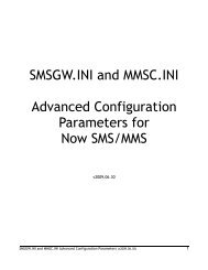
B.4.8.4Operation of the SP Lock<br />
The operation of the SP Lock is shown in detail on the flowchart attached. The stages of operation<br />
are described below.<br />
B.4.8.4.1 MCC/MNC Lock.<br />
When a handset is produced, it shall have a bit (or bits) in EEPROM to tell its operating system that<br />
the MCC/MNC lock is enabled (SPL = active). This bit shall always be active at manufacture. The<br />
MCC/MNC data shall be set to the HPLMN operators values at time of manufacture. In this way<br />
the handset is already locked to HPLMN SIMs after the completion of the manufacture process.<br />
B.4.8.4.2 SP Lock<br />
The SIM will be provisioned with a Service Provider ID contained within the GID1 field. The SIM<br />
will be paired with the handset (At the distribution warehouse for instance), and to avoid there<br />
being problems with acceptance testing of ME's performed using test SIMs, the ME shall read the<br />
SP lock data from GID1 and store this into the protected MSPID EEPROM field only if specific<br />
Autolock criteria are met. Details of the Autolock criteria are given below.<br />
Normal customer SIMs will be such that they fulfill the Autolock criteria and cause the GID1<br />
values to be read, encrypted and stored into an area of ME internal non-volatile memory (MSPID)<br />
when the ME is first turned on with the customer card inserted. After first operation of Autolock the<br />
Lock Enable Status bit (LES) is set indicating that the 'one shot' locking has been carried out.<br />
From this point on, only HPLMN SIMs that contain this SP code shall be allowed to work with this<br />
handset until such time as the ME is unlocked. (Except type approval 001-01 test SIMs)<br />
B.4.8.5Unlocking The Subsidy Protection Lock<br />
The ME shall be populated with at least an 8 digit SP unlocking code that is either calculated from<br />
the IMEI (and optionally the GID1 field contents), or is randomly populated.<br />
If the MCC/MNC lock is on (SPL = active) and a SIM of another network is inserted, then the ME<br />
shall deny service and request the entry of the SP unlocking code. The ME checks the value of the<br />
code entered. If it is correct, then the MCC/MNC lock status bit(s) forming SPL shall be cleared.
<strong>CPHS</strong> version 4.2 27 February 1997 Page 28 of 31<br />
If the code is incorrect, then the periodic timeout interval which must be waited before subsequent<br />
unlock attempts are accepted shall be increased.<br />
The initial timout period is 30 seconds. This shall double at each incorrect attempt until a maximum<br />
value of 2048 * 30 seconds (approximately 17 hours).<br />
NOTE It is preferable that the unlocking of the SP and MNC/MCC are simultaneous and upon<br />
entry of the same unlocking code.<br />
B.4.8.6Requirements of the SIM<br />
The GID1 field details can be found in GSM 11.11 version 4.14 or later.<br />
The field in directory 7F 20 / 21 and has identifier 6F 3E<br />
B.4.8.7Autolock Criteria<br />
The Autolock operation shall take place only when the SIM inserted meets all the following<br />
criteria:-<br />
i) The IMSI has an MNC and MCC corresponding to the HPLMN Operator.<br />
ii) The access class is anything other than 15<br />
iii) There is a GID1 on the SIM which is allocated and activated and whose value lies in the<br />
range 00 to FE inclusive<br />
iv) The operator name string stored on the SIM is not equal to 'GOODS-IN'<br />
B.4.8.8Security handling details<br />
The SP Lock is necessary to protect the handset subsidy value on each ME sold.<br />
The details of the implementation are therefore considered to be high security risk pieces of<br />
information for which special handling measures shall be taken as follows:-<br />
i) Within the Supplier's premises the number of people with knowledge of the implementation<br />
and data storage details shall be kept to an absolute minimum.<br />
ii) The algorithms and other information used to generate the lock codes applicable to individual<br />
ME's shall be held securely and only executable versions shall be available to production<br />
staff. Access to the source routines shall be by controlled access by authorised staff only.<br />
Any executable version should not be able to be copied and run on separate PC equipment.<br />
Acceptable measures to prevent this include the use of hardware keys to limit the operation of<br />
the code to individual machines.<br />
iii) No plain storage of codes and flags shall be available in the ME. These should be held in<br />
encrypted form preferably with integrity check bits built in, or with cross checking between<br />
data stored in different physical devices. In the event of detecting a mismatch in data or check<br />
bits indicating that a fraudulent attempt has been made to alter the data, the ME shall<br />
immediately enter the disabled state.<br />
iv) The Supplier shall take all reasonable measures to ensure that no pieces of equipment are<br />
supplied to third parties, including approved third party test and repair centres, which allow<br />
security codes to be read or altered.<br />
v) The Supplier shall ensure that there are no versions of code supplied to any world market<br />
which would be able to be loaded on the same hardware platform and which do not take<br />
account of the SPL flags.
<strong>CPHS</strong> version 4.2 27 February 1997 Page 29 of 31<br />
In this way it shall not be possible to re-boot the HPLMN operators phones with other<br />
available versions of code and defeat the security of the SP lock.<br />
Power on ME<br />
Is LES Set?<br />
N<br />
Is<br />
ALOCK = TRUE<br />
?<br />
Y<br />
Read GID1<br />
Copy to<br />
Y<br />
N<br />
Set LES<br />
Display "SP<br />
Lock now on"<br />
Y<br />
Is<br />
IMSI = 001<br />
N<br />
N<br />
N<br />
Y<br />
Is<br />
SPL Active<br />
?<br />
Y<br />
Read IMSI<br />
N<br />
HPLMN<br />
IMSI ?<br />
Y<br />
Read GID1<br />
Is<br />
GID1=MSPID<br />
?<br />
LES: Lock Enable Status . 1 bit flag SET if autolock has been<br />
(Default = CLEAR)<br />
ALOCK: A set of conditions on a SIM that the ME reads to know if to<br />
or not.<br />
SPID: Service Provider, Field in GID1 on the SIM contains unique<br />
provider code.<br />
MSPID: A copy of the GID1 in the ME, made when autolock takes place.<br />
Once field. 8 bits<br />
SPL: Subsidy Protection Lock . 1 bit flag if SET ME checks GID1 and<br />
MCC/MNC before granting service. (Default =<br />
SIMUC: SIM Unlocking 8 decimal digit used to deactivate SPL.<br />
based on the IMEI of the ME and calculated/stored by<br />
To: TImeout interval repeat counter. Used to increase delay before<br />
code re-entry attempt following incorrect code entry. Range 0 to<br />
Note: Default is the state in which the ME is upon initial<br />
N<br />
Display "Enter SIM<br />
Unlocking Code"<br />
Is code =<br />
SIMUC?<br />
Y<br />
Deactivate SPL<br />
Display "Phone<br />
Unlocked"<br />
Normal Service<br />
End<br />
N<br />
To = T0 * 2<br />
Display<br />
Security Timeout<br />
Emergency calls only<br />
Wait To intervals<br />
Figure 3 - Flow chart of Network and SP Lock functionality
<strong>CPHS</strong> version 4.2 27 February 1997 Page 30 of 31<br />
B.4.9<br />
Language Reset<br />
It is often the case that handsets can be set into a language mode which the user does not understand<br />
and can find it extremely difficult to reset to a language which is readable. This specification<br />
provides a simple mechanism whereby a handset can be set to a language of choice or to an<br />
automatic mode whereby it sets itself to the language determined by the MCC of the IMSI stored on<br />
the SIM card.<br />
When a code is entered in the format specified below, it shall set itself into the language indicated,<br />
provided that language is supported. If the language is not supported, then the automatic mode shall<br />
be entered.<br />
*# #<br />
FOLLOWED BY “SEND”<br />
E.g. If the user wishes to select English, then *#0044# shall be entered. If the user wishes to select<br />
Finnish, then *#0358# shall be entered.<br />
In the situation where a language may be indicated by two or more country codes (e.g. English; UK,<br />
USA, Australia etc.), the handset shall implement either all applicable codes, or the one which is<br />
most applicable to the destined market.<br />
Automatic mode shall be entered by entering *#0000# followed by “SEND”.<br />
B.4.10Engineering Mode and SW version indication<br />
It is common for a network operator to require the handset to support an engineering mode,<br />
whereby details of signal level, cell ID, carrier number etc. are displayed to the user. It is also<br />
common for the operator to require the handset to give its SW version to the user when a specific<br />
code is given.<br />
However, this information shall not be given to a normal subscriber. It is imperative that the ME<br />
can determine an “authorised” user from a normal subscriber. This is done by checking the access<br />
class field on the SIM. If the subscriber has access class 15 (PLMN staff), then applicable codes<br />
may be used to determine the SW version or to display an engineering mode<br />
B.4.11SIM Toolkit<br />
In order to utilise fully the provisions of the <strong>Phase</strong> 2+ SIM toolkit features, it is recommended that<br />
ME manufacturers implement class 3 SIM Toolkit functionality as soon as practically possible
<strong>CPHS</strong> version 4.2 27 February 1997 Page 31 of 31<br />
Appendix 1<br />
Modifications to GSM Recs. to support ALS<br />
This page contains details of the additions to GSM recommendations 02.30, 04.08 and 09.02 made<br />
in order to support Alternate Line Service. Note that the information below does not include all<br />
other GSM specified values and should be used as an addendum to the GSM specifications.<br />
02.30<br />
An additional MMI service code is defined to give the new ALS teleservice “Auxiliary telephony.<br />
Telecommunication Service<br />
MMI Service Code<br />
Teleservices<br />
All teleservices 10<br />
Telephony 11<br />
Auxiliary Telephony 89<br />
All data teleservices 12<br />
.................<br />
04.08<br />
The bearer capability information element is modified to give an additional “information transfer<br />
capability”<br />
Information transfer capability (octet 3)<br />
Bits<br />
3 2 1<br />
0 0 0 speech<br />
0 1 1 facsimile group 3<br />
1 1 0 auxiliary speech (note)<br />
1 1 1 alternate speech/facsimile group 3<br />
.......<br />
Note:<br />
This value is treated by the network as speech.<br />
09.02<br />
An additional teleservice code is added to those which are currently specified.<br />
TeleServiceCode<br />
Contents<br />
00000000<br />
00010000<br />
00010001<br />
00010010<br />
11010000<br />
11010001<br />
.......<br />
Meaning<br />
All teleservices<br />
Speech transmission<br />
Telephony<br />
Emergency calls<br />
Auxiliary speech<br />
Auxiliary telephony<br />
.......