Dental implants: A different perspective (part 2) - Nobel Biocare
Dental implants: A different perspective (part 2) - Nobel Biocare
Dental implants: A different perspective (part 2) - Nobel Biocare

You also want an ePaper? Increase the reach of your titles
YUMPU automatically turns print PDFs into web optimized ePapers that Google loves.
<strong>Dental</strong> <strong>implants</strong>:<br />
A <strong>different</strong> <strong>perspective</strong> (<strong>part</strong> 2)<br />
Clinical debate<br />
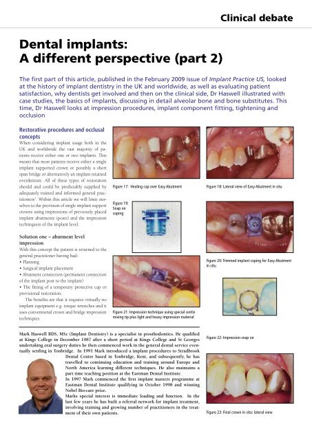
The first <strong>part</strong> of this article, published in the February 2009 issue of Implant Practice US, looked<br />
at the history of implant dentistry in the UK and worldwide, as well as evaluating patient<br />
satisfaction, why dentists get involved and then on the clinical side, Dr Haswell illustrated with<br />
case studies, the basics of <strong>implants</strong>, discussing in detail alveolar bone and bone substitutes. This<br />
time, Dr Haswell looks at impression procedures, implant component fitting, tightening and<br />
occlusion<br />
Restorative procedures and occlusal<br />
concepts<br />
When considering implant usage both in the<br />
UK and worldwide the vast majority of patients<br />
receive either one or two <strong>implants</strong>. This<br />
means that most patients receive either a single<br />
implant supported crown or possibly a short<br />
span bridge or alternatively an implant retained<br />
overdenture. All of these types of restoration<br />
should and could be predictably supplied by<br />
adequately trained and informed general practitioners<br />
1 . Within this article we will limit ourselves<br />
to the provision of single implant support<br />
crowns using impressions of previously placed<br />
implant abutments (posts) and the impression<br />
techniquess of the implant level.<br />
Solution one – abutment level<br />
impression<br />
With this concept the patient is returned to the<br />
general practitioner having had:<br />
• Planning<br />
• Surgical implant placement<br />
• Abutment connection (permanent connection<br />
of the implant post to the implant)<br />
• The fitting of a temporary protective cap or<br />
provisional restoration.<br />
The benefits are that it requires virtually no<br />
implant equipment e.g. torque wrenches and it<br />
uses conventional crown and bridge impression<br />
techniques.<br />
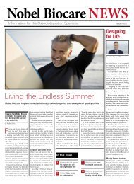
Figure 17: Healing cap over Easy Abutment<br />
Figure 19:<br />
Snap on<br />
coping<br />
Figure 21: Impression technique using special centix<br />
mixing tip plus light and heavy impression material<br />
Figure 18: Lateral view of Easy Abutment in situ<br />
Figure 20: Trimmed implant coping for Easy Abutment<br />
in situ<br />
Mark Haswell BDS, MSc (Implant Dentistry) is a specialist in prosthodontics. He qualified<br />
at Kings College in December 1987 after a short period at Kings College and St Georges<br />
undertaking oral surgery duties he then commenced work in the general dental service eventually<br />
settling in Tonbridge. In 1991 Mark introduced a implant procedures to Stradbrook<br />
<strong>Dental</strong> Centre based in Tonbridge, Kent, and subsequently, he has<br />
travelled to continuing education and training around Europe and<br />
North America learning <strong>different</strong> techniques. He also maintains a<br />
<strong>part</strong> time teaching position at the Eastman <strong>Dental</strong> Institute.<br />
In 1997 Mark commenced the first implant masters programme at<br />
Eastman <strong>Dental</strong> Institute qualifying in October 1998 and winning<br />
<strong>Nobel</strong> Bio-care prize.<br />
Marks special interest is immediate loading and function. In the<br />
last few years he has built a referral network for implant treatment,<br />
involving training and growing number of practitioners in the treatment<br />
of their own patients.<br />
Figure 22: Impression snap on<br />
Figure 23: Final crown in situ: lateral view
Clinical debate<br />
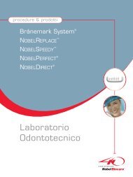
Figure 110: Custom gold posts and Procera crowns Figure 111: Custum abutments in place Figure 112: Final Procera crowns in place<br />
Figure 51: Titanium abutment and crown Figure 54: Abutments in position Figure 93: Temporary crown in situ<br />
Figure 94: Ceramic abutment in situ ready to have<br />
abutment level impression<br />
Figure 95: Procera coping to be used as impression<br />
coping<br />
Figure 96: Coping fitted over abutment ready for<br />
impression<br />
Abutment level impression<br />
The patient will be returned from the implant<br />
centre with a previously installed abutment.<br />
Abutments fall into two basic categories for cementable<br />
single crowns which is by and large<br />
the norm for contemporary implant practice.<br />
1. The abutments are either prefabricated by<br />
the manufacturer with components to ease the<br />
impression procedure (Figures 17-23) or alternatively<br />
are customised abutments. These are<br />
manufactured or adapted from stock abutments<br />
either laboratory-prepared and customised<br />
gold abutments or alternatively CAD-CAM produced<br />
titanium or zirconia abutments (Figures<br />
110-112, 51, 54, 93-97). Any of these will be<br />
fitted by the implant centre and fitted with an<br />
interim protective cap either in the form of a<br />
prefabricated protective cap or alternatively a<br />
provisional crown restoration (Figures 93-97).<br />
2. The impression procedure within the general<br />
practice should take place after sufficient time<br />
for soft tissue maturation. This will need to be<br />
determined by the implant surgeon depending<br />
on the procedures that have been used.<br />
At this stage the aim of the procedure is to<br />
take an accurate location of the position of the<br />
implant abutment in relationship to the adjacent<br />
teeth and gingival tissues and an accurate<br />
recording of the opposing arch. Below I have<br />
detailed two examples the first is with an Easy<br />
Abutment (<strong>Nobel</strong> <strong>Biocare</strong>) the second is with a<br />
customised gold abutment fabricated by a dental<br />
technician.<br />
Easy Abutment: appointment one<br />
Stage one is to remove the temporary protective<br />
healing cap with a small uni-grip screwdriver.<br />
(Figure 17)<br />
Stage two: first fill the central screw hole with<br />
the supplied rubber bung or soft wax Is (then<br />
fit into position by pushing the impression<br />
coping over the abutment the plastic impression<br />
coping). The plastic impression coping<br />
should snap cleanly into place. (Figures 19<br />
and 20).and fill the central screw hole with<br />
the supplied rubber bung or soft wax.<br />
Figure 97: Components necessary for abutment level<br />
impression of customised impression<br />
Stage three is then to choose a rigid sized<br />
stock tray to fit over the teeth and the coping<br />
with no interference or contact.<br />
Stage four is then to syringe in to the impression<br />
coping a light body material of an addition<br />
cured silicone or a polyether. At the same<br />
time as this the tray is loaded with a heavy<br />
body material or monophase material and a<br />
conventional crown and bridge impression<br />
is taken over the top of this (Figures 21 and<br />
22). The press fit impression coping should<br />
remain firmly adhered within the impression
Clinical debate<br />
material. The coping design will ensure adequate<br />
definition of the margins of the abutment.<br />
Stage five will then be for the refitting of the<br />
healing coping after first removing the screw<br />
hole filling. Afterwards the ‘Abutment’ impression<br />
and the opposing impression should<br />
be sent to a laboratory trained in the use of the<br />
selected implant system. This is essential as a<br />
<strong>different</strong> techniques will be required to make<br />
the model and prepare the die, on which to<br />
make a standard crown.<br />
Easy Abutment: appointment two<br />
Stage six: At the fitting appointment, the<br />
temporary crown or healing cap should be<br />
removed. The crown should be tried in. It<br />
should be checked for accuracy of fit, contact<br />
points and occlusal contacts (please see section<br />
on occlusion). The crown will then need<br />
to be cemented.<br />
Stage seven involves cementation. It is essential<br />
to protect the head of the screw (should<br />
the screw every need to be retightened). The<br />
easiest way to protect this head of the screw<br />
is to use soft wax over the top of the screw or<br />
alternatively preformed rubber bungs that are<br />
constructed by implant manufacturers, alternatively<br />
light bodied silicone that can be injected<br />
over the head of the screw or plumbers<br />
tape (Figures 57 and 58). Then cementation<br />
of the crown can be undertaken either with<br />
‘Temp-Bond’ to ensure that access to the screw<br />
can be gained in the future or, a proprietary<br />
implant cement such as ‘Improv’ (Alvelogro<br />
Inc) or Premier (Premier <strong>Dental</strong> Products<br />
Co) or alternatively conventional crown and<br />
bridge cement such as zinc phosphate. Resin<br />
bonding cements and resin modified glass<br />
ionomers should be avoided as it may be impossible<br />
to remove a crown should the screw<br />
need attention in the future.(Figures 23 and<br />
98)<br />
Figure 57: Filling of the screw access hole with PTFE<br />
tape<br />
Figure 23 Final crown in situ: lateral view<br />
Customised abutments and<br />
impression technique<br />
Patient will be delivered back to general practice<br />
with a customised abutment in situ together<br />
with a provisional restoration over the top of<br />
this, to allow for soft tissue maturation and also<br />
guided healing of the soft tissues.<br />
At the first appointment it will be necessary<br />
for the dentist to record the position of the implant<br />
and customised abutment together with<br />
the soft tissue. This is performed utilising the<br />
supplied impression coping. This can be either<br />
of a resin design a metal coping and to form<br />
substructure of a porcelain bonded restoration<br />
or alternatively a ceramic coping to form the<br />
basis of an all ceramic restoration. (Figures 94-<br />
96)<br />
A. Remove the temporary crown and clean<br />
and debride the abutment and remove any<br />
trace of temporary cement.<br />
B. Fit into position the impression coping.<br />
C. Take an impression of the coping and surrounding<br />
teeth and soft tissue and then of the<br />
opposing arch.<br />
Figure 58: Obturated screw access hole<br />
Figure 98: Improv implant specific cement<br />
D. Re-fit the temporary crown after which the<br />
models and shade should be returned to the<br />
technician for the construction of the final restoration.<br />
At this point it should be noted the<br />
aim of the impression procedure is to have the<br />
coping securely locked into position within<br />
the impression and an accurate recording of<br />
the soft tissues together with the surrounding<br />
teeth. Any invasion of the impression material<br />
inside the coping will to show that the coping<br />
was not correctly seated.<br />
At the second appointment fit the final<br />
restoration, this will be undertaken using the<br />
same procedure and it cements to the example<br />
above.<br />
Implant level impressions (fixture head<br />
impression open tray)<br />
This will provide the general practitioner with<br />
the opportunity to take an impression of the top<br />
of the implant and then in conjunction with the<br />
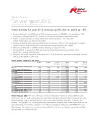
Figure 24: Straumann healing abutment in situ Figure 25: Ankylos healing abutment in situ Figure 26: Replace Select healing abutment in situ
Clinical debate<br />
Figure 27: Torque wrench and screwdriver<br />
Figure 29: X-rays showing healthy bone level<br />
Figure 31: X-rays showing healthy bone level<br />
Figure 28: Check the X-ray to ensure accurate seating<br />
of components to give record of implant bone levels<br />
Figure 30: X-rays showing healthy bone level<br />
Figure 32: Open tray impression with screw hole<br />
visible<br />
dental technician to design the abutment and<br />
the final crown restoration.<br />
In this scenario the patient will be returned<br />
to the general practitioner with the implant in<br />
situ and a healing cap attached to the top of the<br />
implant.<br />
Stage one will be for the construction of the<br />
implant level impression. It requires removal<br />
of the healing cap from the implant (Figures<br />
24-26). The healing cap should be placed either<br />
into sterile saline or Corsodyl (GSK UK)<br />
once it has been unscrewed from the implant<br />
using a hand screwdriver (Figure 27) during<br />
the impression procedure.<br />
A correctly sized impression coping should<br />
then be fitted to the implant (Figures 33 and<br />
35) and the accuracy of fit should be checked<br />
with an X-ray (Figures 28-31). This will also ensure<br />
that the practitioner has a baseline recording<br />
of the bone health and levels in and around<br />
their implant.<br />
Figure 32 shows an open tray impression<br />
coping this is an impression coping that will<br />
protrude through a hole which is cut into either<br />
a special tray or alternatively a rigid stock tray.<br />
This requires a <strong>different</strong> impression procedure<br />
compared to normal crown and bridge. Once<br />
practiced is simpler and more predictable than<br />
most conventional crown and bridge impressions.<br />
Once the accuracy of the location of the impression<br />
post has been checked and its tightness<br />
is ensured by finger tightening the screw.<br />
secured the impression post must be as finger<br />
tight This is achieved by using the small screwdriver<br />
(Figure 27), which will be provided by<br />
the manufacturer and or implant referral centre.<br />
The passive location of the tray with a small<br />
hole is then checked. The tray should then be<br />
loaded with desired material with the dentist<br />
keeping one finger over the opening in the tray<br />
to prevent the impression material pouring onto<br />
the floor and to allow for the correct orientation<br />
of the tray as it will be possible for the dentist<br />
to feel the top of the screw protruding through<br />
the hole as he seats the impression tray into the<br />
correct position (Figure 32).<br />
Once the impression material has set the<br />
impression screw must be released. The screw<br />
is undone until there are no bindings in the<br />
threads and then the post is withdrawn 1-2mm<br />
to ensure there is no overlap between the impression<br />
screw and the implant. The impression<br />
is then withdrawn and the healing cap is immediately<br />
fitted back into position as tight as is as<br />
achievable with finger pressure. The impression<br />
is check to ensure that the impression copings<br />
are securely held in the impression (Figures<br />
36-38).<br />
Design of the abutment and crown at this<br />
stage is done in conjunction with an experienced<br />
technician. The practitioner will need to<br />
decide on the type of abutment to be used and<br />
also the design and materials for the crown. As<br />
detailed above the abutments can be either prefabricated<br />
by the manufacturers or alternatively<br />
customised either by the laboratory or by the<br />
productions facilities such as Cares TM and or<br />
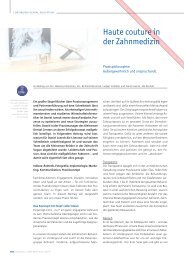
Figure 33: Fixture<br />
head impression of a Straumann implant<br />
Figure 34: Opentray impression coping in situ<br />
Figure 35: <strong>Nobel</strong> replace
Clinical debate<br />
Figure 36: Impression of a Straumann implant<br />
Figure 37: Successful impression of tooth and Ankylos<br />
implant<br />
Figure 38: Completed impressions of Replace Select<br />
implant<br />
Figure 39: Straumann abutment and crown Figure 40: Ankylos abutment and fitting jig Figure 41: Packing moistened Bio-Oss (local anaesthetic)<br />
Procera TM . Once the abutment has been chosen<br />
and adjusted or customised, the restoration can<br />
be constructed either of all ceramic material or<br />
alternatively conventional porcelain bonded to<br />
metal. (Figures 39-41, 110-112 overleaf)<br />
Stage two involves delivery of the crown and<br />
abutment to the patient will be for the removal<br />
of the healing abutment and then be<br />
for the securing of the abutment. This is often<br />
achieved using a fitting jig to ensure the accurate<br />
orientation of the abutment this helps<br />
<strong>part</strong>icularly the inexperienced practitioner<br />
as it ensures that the abutment is correctly<br />
orientated(Figures 40 and 55).<br />
Once the abutment has been secured and<br />
checked radiographically to ensure an accurate<br />
fit between the abutment and the implant head<br />
(Figures 62-64) with no intervening soft tissue<br />
or gap. The crown needs to be tried in to assess<br />
the fit, aesthetics and contour. Once both the<br />
patient and the practitioner are happy with this<br />
the abutment must be tightened into position.<br />
Abutment tightening<br />
This is undertaken using a hand torque device.<br />
At this stage the torque device is connected<br />
to the screw and the screw is tightened<br />
slowly using the torque wrench, to achieve at<br />
the prescribed torque. This will be marked on<br />
the graduated scale of the torque wrench or designed<br />
into the device. (Note that these will vary<br />
depending on the manufacturer of the implant<br />
and should be checked to ensure that the screw<br />
is tightened optimally. Excess force could fracture<br />
the screw, while insufficient force will leave<br />
the patient with a potential weak screw joint<br />
prone to screw loosening. Once the adequate<br />
required torque is reached the screw should be<br />
left for two to five minutes before retightening<br />
to the same prescribed torque. This allows for<br />
the embedment relaxation of the screw and will<br />
allow the screw to perform optimally. (Figures<br />
55 and 56)<br />
Fill the abutment screw hole will be with<br />
either a soft wax, an impression silicone, a resilient<br />
material such as a gutta percha covered<br />
with a composite resin if so required or PTFE<br />
(plumbers) tape. (Figures 57 and 58)<br />
This will prevent cement interfering with<br />
the screw head which could prevent access in<br />
the future.<br />
Fitting of the crown can be done using either<br />
temporary cement (Premier or Improv),<br />
proprietary implant cement or alternatively<br />
a zinc phosphate type material. It is essential<br />
that when securing the crown excessive cement<br />
is not placed into the crown as excessive cement<br />
can and will be exuded into the gingival<br />
pocket. This can be difficult to clean resulting<br />
in implant cement residue around the implant<br />
head leading into peri-implant inflammation if<br />
left untreated. (Figure 99) It is also possible, if<br />
extreme amounts of cement are applied to the<br />
inside of crowns, for the cement to be forced<br />
down the side of the implant abutment down<br />
towards the implant. This is something to be<br />
avoided at all costs.<br />
Occlusion<br />
Why is occlusion important to an implant restoration?<br />
The <strong>implants</strong> successful healing to the bone<br />
creates a rigid fixation with virtually no movement<br />
(approximately five microns). However a<br />
healthy tooth will intrude by 28 microns 27 supported<br />
by the periodontal ligament. The periodontal<br />
ligament is the fundamental difference<br />
between the implant and the tooth.<br />
The tooth is cushioned by the ligament,<br />
which acts as a shock absorber. The tooth also<br />
has a protective feedback from the periodontal<br />
mechano- receptors. Therefore, the presence of<br />
excess load (a high restoration) on a tooth will<br />
elicit a sensation from the patient. This may be<br />
as simple as the patient complaining that the<br />
restoration is ‘high’ and ‘none of their other<br />
teeth contact’ or it may create mobility or sensitivity<br />
in the tooth.<br />
An implant doesn’t have the cushion or the<br />
reflex. Therefore the patient will not detect the<br />
‘high’ restoration. The implant will then experience<br />
excessive load with little feedback. The<br />
implant does not have the physiologic adaptability<br />
to alter its position caused by its excessive<br />
load much as a tooth might or to report<br />
pain/discomfort centrally. The implant would<br />
therefore continue to be overloaded. Overload<br />
has been shown to be the major cause of implant<br />
failure.<br />
It is the restoring dentist’s responsibility to<br />
ensure that the implant is not exposed to excess<br />
load. 9
Clinical debate<br />
Figure 62: Post fit check X-ray Figure 63: Post fit check X-ray Figure 64: Post fit check X-ray<br />
The excessive force causes micro fractures in<br />
the bone – implant interface that cannot regenerate<br />
so they repair themselves with poorly <strong>different</strong>iated<br />
scar tissue resulting in a soft tissue<br />
interface and ultimately a loose implant.<br />
Occlusal perception is the ability of the patient<br />
to feel a sensation between the upper and<br />
lower jaw when a foreign body is between the<br />
occlusal surfaces. Here are the protocols:<br />
• Tooth against tooth - 20 microns<br />
• Implant against tooth - 48 microns<br />
• Implant against implant - 64 microns. 30,28<br />
This shows that the implant restoration<br />
against a natural tooth will require the<br />
restoration to be twice as high before it will be<br />
detected.<br />
Patients will have a reflex to avoid the high<br />
occlusal contact with teeth. However this will<br />
not happen with <strong>implants</strong>.<br />
This fundamental difference between teeth<br />
and <strong>implants</strong> directs us to the fact that <strong>implants</strong><br />
long-term health and stability is determined<br />
by carefully adjusted occlusal contacts. This<br />
is especially important, as the patient will be<br />
less well able to report any problems. Therefore<br />
careful assessment of contacts is essential for<br />
the adjustment of these contacts.<br />
What are the biomechanical risk<br />
factors. Can we spot patients more at<br />
risk of overload?<br />
i.• History of bruxism or clenching<br />
ii.• Excessive guidance on restorations<br />
iii.• Poor anterior guidance and disclusion in<br />
the dentition as a whole (making excursive<br />
contacts more likely.<br />
• History of fractured teeth.<br />
Is it possible to reduce the effects of these risk<br />
factors:<br />
1. Use of nocturnal occlussal splint<br />
2.Design occlusal surface of restoration to avoid<br />
being the major guiding “tooth” in a <strong>part</strong>icular<br />
Figure 55: Abutments torqued into position locating<br />
jig in position<br />
Figure 100: X-ray of split implant<br />
movement path.<br />
3. Adjust or restore the remainder of the dentition<br />
to allow stable contacts and protective disclusion<br />
2 .<br />
4. Ensure sufficient guidance from the remainder<br />
of the dentition to prevent the implant restoration<br />
being excessively loaded in excursive<br />
movements.<br />
Designing the implant restoration to withstand<br />
occlusal load needs avoidance of premature<br />
contacts on the implant-supported<br />
restorations.<br />
This should ensure all the natural teeth and<br />
implant restorations touching at the same time<br />
Figure 56: Abutments torqued into position locating<br />
jig in position<br />
Figure 101: Failure due to overload with split implant<br />
in centric occlusion.<br />
However one additional factor has to be<br />
borne in mind. When teeth first contact they<br />
will compress into their socket more due to the<br />
viscoelasticity of the periodontal ligament. An<br />
implant will not! Therefore the implant will be<br />
left high by the movement of the teeth within<br />
the periodontal ligament!<br />
Solution<br />
Adjust the implant restoration – the implant<br />
crown should be adjusted with thin articulating<br />
paper (less than 25 microns, thin articulating paper<br />
20 microns Acufilm: Parkell, Farmingdale,
Clinical debate<br />
Figure 102: Schimstock foil used to check the occlusal<br />
contact in centric occlusion on lower molar<br />
Figure 103: Occlusal contacts on the lower first molar<br />
implant crown<br />
Figure 99: X-ray of crown whosing excess cement is on<br />
the distal surface of implant<br />
Figure 107: Shows a narrow occlussal table molar<br />
crown on a wide diameter implant<br />
NY). The occlusion should be adjusted with the<br />
patient only lightly while tapping, their teeth<br />
together. There should barely be any contact<br />
when lightly tapping together. This can be verified<br />
by drawing through Schimstock foil (Hanel,<br />
Roeko) whilt the teeth are lightly held together.<br />
The same faoil should be held by the implant<br />
and opposing tooth when heavy bite forces are<br />
is applied (Figures 102 and 103).<br />
The contacts should also be on the centre of<br />
the restoration thereby down the long axis of<br />
the implant.<br />
One must understand that despite the most<br />
accurate impressions and occlusal records all<br />
implant restorations will require adjustment to<br />
have an acceptable level of force when in functionrcation.<br />
This is because there is no way for<br />
a technician to allow for the compression of the<br />
periodontal ligament.<br />
This pattern of occlusal adjustment does not<br />
mean that the opposing tooth has no functional<br />
contact. This periodic contact throughout thea<br />
days function will maintain the position of the<br />
opposing tooth within the occlusion.<br />
Anterior teeth<br />
We must also avoid excursive contacts on implant<br />
restorations in excursive movements.<br />
This will help avoid excessive or parafunctional<br />
forces on <strong>implants</strong>.<br />
When posterior teeth contact in lateral<br />
movements they are subject to greater forces in<br />
lateral directions. The posterior teeth and implant<br />
restorations are much better at withstanding<br />
axial forces. The back teeth can be protected<br />
from these lateral forces if the anterior teeth disengage<br />
the back teeth from each other in lateral<br />
excursive movements.<br />
Can we ensure a reduced risk of lateral<br />
forces?<br />
Check for adequate anterior guidance to create<br />
posterior disclusion prior to commencing<br />
treatment. Consider the creation or enhancement<br />
of anterior guidance to allow disclusion.<br />
If an anterior implant is needed to aid in<br />
the disclusion (guidance) of posterior unit the<br />
guidance should be as shallow as possible to reduce<br />
lateral forces, said Weinberg 30 .<br />
The restoring dentist has the responsibility<br />
to minimise overload to the bone to the implant<br />
interface 18 . In the <strong>part</strong>ially edentulous patient occlusal<br />
forces between teeth and <strong>implants</strong> should<br />
be harmonised 18 . Patients with a parafunctional<br />
habit should be provided with occlusal night<br />
guards, which will minimise destructive forces<br />
18 . Avoid forces that do not go down long axis<br />
of the implant those would be excessive forces 18 .<br />
It is also important to avoid forces that do not<br />
go down long axis of the implant as these would<br />
be excessive forces, as they are multiplied by<br />
the cantlever effect. This is because the forces<br />
would be acting far away from the central line of<br />
support.<br />
Forces away from the central axis of the implant<br />
will place the implant bone interface under<br />
sheet and tension load which is disadvantageous<br />
to the bone. Ideally an implant should be<br />
loaded so that the implant bone interface is in<br />
compression.<br />
Therefore the implant body should be perpendicular<br />
to the occlusal plane. The orientation<br />
of the implant. This is the responsibility of<br />
the implant surgeon. This is of primary importance<br />
when restoring single posterior units.<br />
Should implant crowns be the same<br />
size as natural teeth?<br />
The vast majority of <strong>implants</strong> placed will have<br />
a smaller diameter than the tooth they replace.<br />
Therefore to place a restoration the same dimension<br />
as the natural tooth will create overhangs<br />
(cantilevers), like placing an apple on a<br />
stick. This situation can result in tipping forces<br />
over the implant edge. These off-axis forces will<br />
tend to load the implant and bone in less advantageous<br />
ways. This can potentially lead to<br />
overload of the implant bone interface.<br />
The solution is to have a narrower prosthesis<br />
especially in areas of high occlusal load i.e. molar<br />
replacements (Figures 102 and 107). This<br />
however does not take into account the mesiodistal<br />
dimension which must match the missing<br />
tooth. The occlusal contact should be over<br />
the long axis of the implant body. Contact at<br />
the mesial and distal marginal ridges should be<br />
carefully adjusted to relieve multiplying forces,<br />
far removed from the long axis of the implant<br />
especially in areas of high load. (ie. The occlusal<br />
contact should be straight down the screw<br />
holding the abutment to the implant). (Figure<br />
103)<br />
Advantages of narrow occlusal tables<br />
i) Greater force concentration (like a sharp<br />
knife)<br />
ii) Reduce off axis loads (tipping and twisting<br />
forces)<br />
iii) Less risk of veneer material fracture.<br />
Clinical signs of implant overload:<br />
1. Abfraction<br />
2. Decementation of restorations<br />
3. Screw loosening
Clinical debate<br />
Figure 108: Failed anterior bridge 1 1<br />
Figure 109: Replacement implant at 1 1 after<br />
immediate replacement and bone augmentation<br />
Figure 110: Custom gold posts and Procera crowns<br />
4. Component fracture<br />
5. Veneer material fracture<br />
6. Implant failure.<br />
Are <strong>implants</strong> for everyone?<br />
Not necessarily but they could be working in a<br />
team structure most patients can be treated by<br />
the general practitioner with the surgical input<br />
of the implant surgical centre. Team dentistry is<br />
illustrated in Figures 108-112.<br />
Conclusions<br />
1. A continued rapid increase in demand for<br />
dental <strong>implants</strong> is likely to be seen in the UK.<br />
2. There is likely to be a shortage of well trained<br />
dentists willing or capable of providing the surgical<br />
services required for implant installation.<br />
3. A network of general practitioners allied to a<br />
surgical centre will be able to provide far greater<br />
number of patients with implant-based restorations<br />
than dentists working in isolation.<br />
4. General practitioners should be able to<br />
provide the vast majority of restorative<br />
solutions for their own patients requiring<br />
implant-based therapy.<br />
Figure 111: Custom abutments in place<br />
References<br />
1. Christensen GJ (2000). Clinical Research<br />
Associates, Provo Utah 84604, USA. Implants<br />
and general practitioners. J Amer Dent Assoc<br />
131:359-361<br />
9. Tallgren A. The continuing reduction of the<br />
residual ridges in complete denture wearers:<br />
a mixed longitudinal study covering 25yrs. J<br />
Prosthet Dent 27: 120 1972<br />
18. Misch C (2005). <strong>Dental</strong> Implant Prosthetics.<br />
Mosby Inc<br />
27. Muhlemann HR, Savdirl S, Rakeitshak,KH<br />
(1965). Tooth Mobility: its cause and significance.<br />
J Periodontol 36:148-153<br />
Figure 112: Final Procera crowns in plane<br />
28. Sekine H, Komiyama Y (1986). Mobility<br />
characteristics and tactile sensitivity of osseointegrated<br />
fixture supporting systems. In<br />
van Steenberghe D, editor: Tissue integration<br />
in oral maxillofacial reconstruction, Amsterdam.<br />
Elsevier<br />
30. Weinberg LA, Kruger G (1995). A comparison<br />
of implant/prosthesis loading for clinical<br />
variables. Int J Prosthodont 8:421-43<br />
Implants by author Mark Haswell<br />
and restorations by referring GDP<br />
Dr S Peter.