Liquid-Level Sensors - MTS Sensors
Liquid-Level Sensors - MTS Sensors
Liquid-Level Sensors - MTS Sensors

Create successful ePaper yourself
Turn your PDF publications into a flip-book with our unique Google optimized e-Paper software.
3.0 INSTALLATION AND MOUNTING<br />
The method of mounting the <strong>Level</strong> Plus M-Series transmitter is dependent on the vessel or tank in which it is being used, and<br />
what type of sensor is being mounted. Most applications will require one of two methods: threaded or flange mounting, shown<br />
in Figures 3-1a and 3-1b below. See section 3.2 for detailed information about Sanitary application mounting.<br />
3.1 Mounting Options for Rigid or Flexible Sensor<br />
3.1a Threaded Flange Mounting<br />
In applications with smaller vessels and tanks, the sensor can be mounted directly to the tank or flange via a<br />
NPT threaded fitting, assuming there is a proper threaded connection available. If the float will not fit<br />
through the flange, there must also be some means to mount the float on the transmitter from inside the vessel;<br />
this may require an access port nearby the entry point of the transmitter (as shown in Figure 3-1a).<br />
First, the float(s) is removed from the transmitter by removing the float retaining hardware. The tip of the<br />
transmitter is inserted through the threaded vessel opening or flange. Before completely inserting the transmitter<br />
to the bottom of the vessel, you must remount the float(s) through an access port and also reattach the<br />
float retaining hardware.<br />
The tip of the transmitter rod can now be lowered to the vessel bottom and the connection can be made from<br />
the threaded NPT fitting to the vessel. In general, there should not be more than 12 inches of the transmitter’s<br />
rod extending above the vessel.<br />
3.1b Welded Flange Mounting<br />
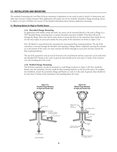
The M-Series transmitter can also be mounted to a tank flange (as shown in Figure 3-1b). First, install the<br />
float(s) onto the transmitter. Second, install the float retaining hardware on the tip of the sensor. To complete<br />
the installation, mount the transmitter, flange and float(s) as a unit in to the tank. In general, there should not<br />
be more than 12 inches of the transmitter’s rod extending above the vessel.<br />
Figure 3-1a<br />
Threaded Flange Mounting<br />
for Rigid and Flexible Pipe<br />
Figure 3-1b<br />
Welded Flange Mounting<br />
for Rigid and Flexible Pipe<br />
NPT Fitting<br />
Riser<br />
Tank flange<br />
(provided by customer<br />
or ordered separately)<br />
Float access port<br />
Welding sleeve<br />
1.125 in.<br />
(28.6 mm) dia.<br />
Flange (welded)<br />
Tank flange<br />
Riser<br />
Stainless steel<br />
flexible sensor pipe<br />
Product<br />
float<br />
Interface<br />
float<br />
Tip of transmitter<br />
Tip of transmitter<br />
Bottom-fixing weight,<br />
magnet, or hook<br />
6