Hydraulic Leveling - Power Gear
Hydraulic Leveling - Power Gear
Hydraulic Leveling - Power Gear

Create successful ePaper yourself
Turn your PDF publications into a flip-book with our unique Google optimized e-Paper software.
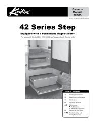
Owner’s Manual<br />
<strong>Hydraulic</strong><br />
<strong>Leveling</strong><br />
CONTENTS<br />
Introduction 1<br />
Operation 2<br />
Control Panel 2<br />
Automatic <strong>Leveling</strong> 3<br />
Manual <strong>Leveling</strong> 3<br />
Retracting Jacks 4<br />
Remote Operation 4<br />
Care & Maintenance 5<br />
Troubleshooting 6<br />
Error Codes 7<br />
Warranty 8<br />
!<br />
CAUTION<br />
READ ALL OPERATING<br />
INSTRUCTIONS FIRST<br />
BEFORE USING POWER<br />
GEAR LEVELING SYSTEM.<br />
1217 E 7th St<br />
Mishawaka, IN 46544<br />
www.<strong>Power</strong><strong>Gear</strong>US.com<br />
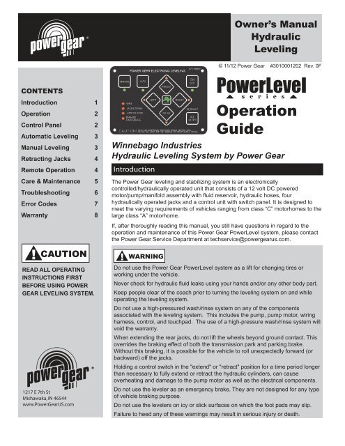
Introduction<br />
© 11/12 <strong>Power</strong> <strong>Gear</strong> #3010001202 Rev. 0F<br />
<strong>Power</strong>Level<br />
s e r i e s<br />
Operation<br />
Guide<br />
Winnebago Industries<br />
<strong>Hydraulic</strong> <strong>Leveling</strong> System by <strong>Power</strong> <strong>Gear</strong><br />
The <strong>Power</strong> <strong>Gear</strong> leveling and stabilizing system is an electronically<br />
controlled/hydraulically operated unit that consists of a 12 volt DC powered<br />
motor/pump/manifold assembly with fluid reservoir, hydraulic hoses, four<br />
hydraulically operated jacks and a control unit with switch panel. It is designed to<br />
meet the varying requirements of vehicles ranging from class “C” motorhomes to the<br />
large class “A” motorhome.<br />
If, after thoroughly reading this manual, you still have questions in regard to the<br />
operation and maintenance of this <strong>Power</strong> <strong>Gear</strong> <strong>Power</strong>Level system, please contact<br />
the <strong>Power</strong> <strong>Gear</strong> Service Department at techservice@powergearus.com.<br />
!<br />
WARNING<br />
Do not use the <strong>Power</strong> <strong>Gear</strong> <strong>Power</strong>Level system as a lift for changing tires or<br />
working under the vehicle.<br />
Never check for hydraulic fluid leaks using your hands and/or any other body part.<br />
Keep people clear of the coach prior to turning the leveling system on and while<br />
operating the leveling system.<br />
Do not use a high-pressured wash/rinse system on any of the components<br />
associated with the leveling system. This includes the pump, pump motor, wiring<br />
harness, control, and touchpad. The use of a high-pressure wash/rinse system will<br />
void the warranty.<br />
When extending the rear jacks, do not lift the wheels beyond ground contact. This<br />
overrides the braking effect of both the transmission park and parking brake.<br />
Without this braking, it is possible for the vehicle to roll unexpectedly forward (or<br />
backward) off the jacks.<br />
Holding a control switch in the "extend" or "retract" position for a time period longer<br />
than necessary to fully extend or retract the hydraulic cylinders, can cause<br />
overheating and damage to the pump motor as well as the electrical components.<br />
Do not use the leveler as an emergency brake, They are not designed for any type<br />
of vehicle braking purpose.<br />
Do not use the levelers on icy or slick surfaces on which the foot pads may slip.<br />
Failure to heed any of these warnings may result in serious injury or death.
<strong>Power</strong>Level Operation Manual Page 2<br />
NOTE: To prevent improper<br />
operation of the leveling<br />
system, which could result<br />
in damage to the levelers<br />
and/or the vehicle itself, read<br />
the operating instructions<br />
carefully before using the<br />
leveling jacks.<br />
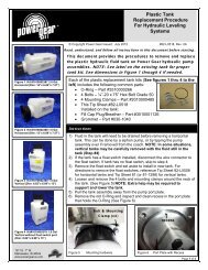
Figure 1<br />
Operation<br />
The <strong>Power</strong>Level system performs the dual function of leveling the vehicle and, once<br />
a level plane has been achieved, stabilizing the vehicle. When leveling the vehicle, it<br />
may not be necessary to use all of the leveling jacks however, to stabilize the<br />
vehicle, all jacks should be extended to contact the ground.<br />
SITE SELECTION<br />
1. When selecting a site for parking the vehicle, choose a spot that is as flat as<br />
possible - this will minimize the extent of leveling.<br />
2. Check that the area under the vehicle is free from any obstacles that might<br />
interfere with the operation of the levelers. Check the ground surface to assure the<br />
leveler feet have a flat solid surface for contact.<br />
NOTE: In occasional adverse driving conditions, it is possible for mud, ice and other<br />
debris to accumulate around the leveler units. This debris may interfere with the<br />
operation and should be cleaned off prior to using the system.<br />
POWER GEAR CONTROL<br />
PANEL LAYOUT<br />
The control panel consists of<br />
switches and light emitting diode<br />
indicators (Figure 1).<br />
The switches include main power<br />
ON/OFF, ALL JACKS retract,<br />
manual and auto leveling and four<br />
jack indicator lights (FRONT,<br />
RIGHT, LEFT and REAR). The<br />
position of the jack indicator lights<br />
correspond to the position of the<br />
jack legs on your motor home, with<br />
the front of the vehicle indicated by<br />
FRONT and the rear of the vehicle<br />
indicated by REAR.<br />
Control Panel Functions<br />
The ON/OFF switch, located in the upper right hand corner, controls the supply of<br />
power for all panel functions, activation of this switch is indicated by its green LED.<br />
The ALL JACKS retract switch is located in the lower right hand corner of the control<br />
panel. Activation of this switch causes all legs to retract to the travel position. When<br />
the retract sequence is completed, the JACKS DOWN and the dash indicator light<br />
will go out to indicate that it is now safe to move the motorhome.<br />
The diamond shaped buttons, located in the center of the panel, activate the<br />
extension of the leveling jacks.<br />
The control has an automatic shut-off feature. Following the last operation, the<br />
control will automatically shut off in 4 minutes.
<strong>Power</strong>Level Operation Manual Page 3<br />
!<br />
COACHES EQUIPPED WITH<br />
AIR SUSPENSION & THE AIR<br />
DUMP FEATURE:<br />
When operating in the<br />
Manual mode air will be<br />
dumped from the vehicle<br />
suspension in approximately<br />
20 seconds.<br />
When operating in Auto<br />
Mode, there will be a 20<br />
second delay before the<br />
jacks begin to extend, while<br />
the air dumps from the<br />
vehicle suspension.<br />
!<br />
NOTICE<br />
NOTICE<br />
For Manual, Automatic and<br />
Remote <strong>Leveling</strong> the vehicle<br />
engine must be running, the<br />
transmission in park and the<br />
parking brake set. Securely<br />
block the rear wheels using<br />
wheel chocks.<br />
Automatic <strong>Leveling</strong><br />
1. Turn on the ignition and start the coach. Your leveling control will start a self<br />
check sequence indicated by the lights on the panel blinking in a rotating pattern. It<br />
will turn off when it has finished it’s self check.<br />
2. Push the "On/Off" button on control panel. The system is now operational and the<br />
“On/Off” LED will turn on.<br />
3. Check to see that the engage park brake light is not illuminated. If so, engage the<br />
parking brake. (Your coach will have to be in neutral or park to operate the system).<br />
4. Push the “AUTO” button. The automatic leveling system will begin it’s leveling<br />
procedure. Please avoid movement in the coach during automatic leveling as it can<br />
cause errors in the results. It will signal that it has completed the process by<br />
illuminating the center green “LEVEL” light. Check to make sure that all jacks are on<br />
the ground. Also check to make sure that no tire is off the ground. If so, your<br />
leveling process is complete. If further adjustments are needed, refer to the “Manual<br />
Operation” section.<br />
5. You can then turn the system off by pushing the on/off button again.<br />
Automatic<br />
mode button<br />
Manual operation<br />
button (push and<br />
hold for 5-7<br />
seconds)<br />
Front Jacks<br />
Button<br />
Right Jack<br />
Button<br />
Locate the “ON/OFF” button<br />
on the upper right of the<br />
control panel. Momentarily<br />
depress this switch to<br />
activate the leveling system.<br />
The LED will light up<br />
indicating that the system is<br />
ready. If the Park Brake LED<br />
lights up, it is an indication<br />
that the parking brake is not<br />
engaged.<br />
!<br />
NOTICE<br />
The Engage Park Brake LED<br />
indicates “Not Engaged”<br />
when lit.<br />
Manual <strong>Leveling</strong><br />
Left Jack<br />
Button<br />
Rear Jacks<br />
Button<br />
There are certain conditions where manually leveling your coach may be desirable.<br />
1. Turn on the ignition and start the coach.<br />
2. Push the “On/Off” button to turn on the system.<br />
3. Push and hold the “MANUAL” button for 5-7 seconds in order for the system to<br />
switch to the manual mode. It will signal that it is in the manual mode when the light<br />
under the “MANUAL” button is illuminated.<br />
4. Push “FRONT” button until the front of the coach rises at least 3 “. This is<br />
important and necessary to allow the coach to pivot when leveling side to side. If<br />
there is insufficient jack stroke to lift the front of the coach at least 3 inches the<br />
coach will have to be moved to an area with less front to back slope, or a weight<br />
distribution block will have to be placed under the jack.<br />
5. Push the “REAR” button until jacks contact the ground.
<strong>Power</strong>Level Operation Manual Page 4<br />
!<br />
To prevent the possibility of<br />
damaging the levelers and/or<br />
vehicle, it is good practice to<br />
confirm the retracted position<br />
by visual inspection.<br />
!<br />
NOTICE<br />
NOTICE<br />
For Remote <strong>Leveling</strong> the<br />
vehicles engine must be<br />
running, the transmission in<br />
park and the parking brake<br />
set. Securely block the rear<br />
wheels using wheel chocks.<br />
If the Park Brake LED lights<br />
upon the main operators<br />
panel, it is an indication that<br />
the parking brake is not<br />
engaged.<br />
6. Level the coach from front to rear by pushing the “REAR” button if the light under<br />
the “REAR” button is illuminated. If the light is illuminated above the “FRONT<br />
JACKS” button, push the “FRONT” button. In either case, keep button depressed<br />
until the green center “LEVEL” light is illuminated, or both front and rear lights are<br />
dark.<br />
7. Level the coach from side to side by pushing the “RIGHT” button if the light<br />
beside the “RIGHT” button is illuminated. If the light beside the “LEFT” button is<br />
illuminated, push the “LEFT” button until the “LEVEL” light is illuminated.<br />
NOTE: The right and left rear jacks are used to level the coach side to side.<br />
Pushing the “LEFT” button on the control panel will extend the left rear jack.<br />
Pushing the “RIGHT” button on the control panel will extend the right rear<br />
jack. There is no individual control of the right or left front jacks on 4 jack<br />
systems. The pressure equalization built into the system shifts the 2 front<br />
jacks.<br />
8. Repeat steps 6 and 7 if needed.<br />
9. Turn power off to leveling system by pushing “ON/OFF” button.<br />
10. Visually inspect jacks to ensure all pads are touching ground. Should one of the<br />
rear jacks not be touching the ground, press the corresponding left or right rear jack<br />
buttons to lower the appropriate jack to the ground. Never lift the wheels off the<br />
ground to level the coach. This can lead to an unsafe condition and damage to the<br />
leveling system or coach.<br />
NOTE: If the “Wait” LED is ever flashing by itself, it means the control is busy<br />
and you cannot operate the jacks. After a short period of time (from 5 to 30<br />
seconds), the “Wait” LED will go off again, and you can resume operation as<br />
normal.<br />
Retracting the Jacks<br />
1. Start the chassis engine or turn the key to the accessory position and turn the<br />
control panel power switch on. If any levelers are extended, the “JACKS DOWN”<br />
LED will light up, and the dash warning light will illuminate. The buzzer will sound<br />
only if the IGN switch is in IGN position (not ACC).<br />
2. To retract all levelers simultaneously, press the "ALL JACKS" retract switch.<br />
3. When all leveler legs retract to the travel position, the yellow "JACKS DOWN"<br />
LED and the dash warning light will go out. You can now turn off the power.<br />
Remote Operation<br />
The control may be turned on to start operation from inside using the on/off button<br />
or outside by pushing the rocker switch to the desired mode of operation. Once<br />
turned on from inside, the LED at the remote switch location will illuminate solid. If<br />
selected from outside the unit, operation will begin immediately.<br />
AUTO MODE: Depress the rocker switch momentarily to the Auto Mode position.<br />
The LED will flash slowly, indicating operation and the system will begin the leveling<br />
process to completion.<br />
Once the operation is complete, the LED at the rocker switch will flash quickly for 2<br />
seconds, then stay illuminated until the control unit times out.<br />
ALL UP: Depress the rocker switch momentarily to the All Up position. The LED will<br />
flash slowly, indicating operation and the system will begin the retraction process to<br />
completion.<br />
Once the operation is complete, the LED at the rocker switch will flash quickly for 2<br />
seconds, then stay illuminated until the control unit times out.
<strong>Power</strong>Level Operation Manual Page 5<br />
!<br />
Your coach must be<br />
supported at both ends of<br />
the chassis frame rails with<br />
jack stands before working<br />
underneath, failure to do so<br />
may result in personal injury<br />
or death.<br />
!<br />
WARNING<br />
NOTICE<br />
It is recommended that<br />
during periods of<br />
vehicle inactivity and/or<br />
storage, the leveling system<br />
should be activated and<br />
cycled through the<br />
leveling/retracting<br />
procedures on a monthly<br />
basis to keep the leveling<br />
jack seals lubricated and in<br />
good operating condition.<br />
STOPPING OPERATION IN MID CYCLE: To stop operation in the middle of a cycle,<br />
depress the remote rocker switch to either position to stop the function or press<br />
on/off on the operators control panel in the coach.<br />
RESTARTING ALL UP AFTER MID-CYCLE STOP: To restart a cycle that had<br />
started and then was stopped by the operator, depress the rocker switch<br />
momentarily to the All Up position to start retracting the jacks again.<br />
RESTARTING AUTO MODE AFTER MID-CYCLE STOP: To restart the Auto Mode<br />
process, depress the rocker switch momentarily to the ALL UP position to retract the<br />
jacks fully. Once completed depress the rocker switch to the Auto Mode position.<br />
(The operator may go directly to the Auto Mode, skipping the retract cycle, however<br />
actual leveling results may vary depending on the stage of the Auto Mode cycle<br />
when stopped. No damage will result from this. If the results are unsatisfactory,<br />
retract the jacks fully and start the cycle over.)<br />
Care and Maintenance<br />
The <strong>Power</strong> <strong>Gear</strong> <strong>Power</strong>Level hydraulic leveling system should be routinely checked<br />
as part of a regular vehicle maintenance program. <strong>Power</strong> <strong>Gear</strong> recommends<br />
checking the system twice a year: in the spring prior to the heavy travel season and<br />
in the winter, prior to storage. The following checklist has been provided as a<br />
guideline for maintenance.<br />
1. Check and/or fill the reservoir with the jacks and room(s) in the fully retracted<br />
position, each month. The fluid should be ¾” onto the dipstick (on models so<br />
equipped) or to the bottom of the fill port on models without dipsticks.<br />
2. Inspect and clean all hydraulic pump electrical connections every 12 months.<br />
3. Remove dirt and road debris from jacks as needed.<br />
4. If jacks are down for extended periods, it is recommended to spray exposed<br />
leveling jack chrome rods with a silicone lubricant every 5 to 7 days for protection.<br />
5. In extreme conditions (within 60 miles of coastal areas), it is recommended to<br />
spray the rods every 2 to 3 days with a silicone lubricant.<br />
6. To maintain proper seal lubrication, grease the fitting on the bottom of each jack<br />
cylinder with Lithium grease every 20-30 uses.<br />
7. Do not use a high pressured wash/rinse system on any of the components<br />
associated with the leveling system. This includes the pump, pump motor, wiring<br />
harness, control, and touchpad. The use of a high pressure wash/rinse system will<br />
void the warranty.<br />
RECOMMENDED HYDRAULIC FLUIDS FOR YOUR HYDRAULIC PUMP<br />
The <strong>Power</strong> <strong>Gear</strong> hydraulic system is filled with automatic transmission fluid from the<br />
factory. If fluid is required after checking the oil level, the recommended<br />
replacement ATF’s are Dexron II or Mercon.<br />
If operating in cold temperatures (less than -10° F) the jacks may extend and retract<br />
slowly.<br />
For cold weather operation, fluid specially-formulated for low temperatures may be<br />
desirable. Mobil DTE 11M, Texaco Rando HDZ-15HVI, Kendall Hyden Glacial Blu,<br />
or any Mil. Spec. H5606 hydraulic fluids are recommended for cold weather<br />
operation.<br />
It is not recommended that hydraulic fluid and automatic transmission fluids be<br />
mixed in the reservoir.<br />
Please consult <strong>Power</strong> <strong>Gear</strong> before using any other fluids than those specified here.
<strong>Power</strong>Level Operation Manual Page 6<br />
Troubleshooting<br />
Locations of breakers, fuses, fuse panels, etc. are coach specific. Consult your<br />
coach owner’s manual or Winnebago Industries for locations of these<br />
components.<br />
The following information will guide you to repairs that may be made on site. For<br />
problems not covered here, contact your service center or our website,<br />
www.powergearus.com for more extensive troubleshooting information in the<br />
service manual for your system.<br />
For your convenience, all Tip Sheets referenced below are in the Reference Section<br />
of the manual, starting on page 9.<br />
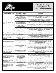
SYMPTOM<br />
System will not turn on, indicator<br />
light does not light.<br />
Jacks will not extend, pump is not<br />
running.<br />
Jacks will not extend, pump is<br />
running.<br />
All jacks will not retract or will not<br />
retract fully.<br />
Any one or two jacks will not retract<br />
at all.<br />
Any jack retracts very slowly.<br />
PROBABLE CAUSE<br />
Coach ignition not in run position.<br />
Transmission not in park or neutral.<br />
Parking brake not set.<br />
Control has been left on for more<br />
than four minutes, auto shut off.<br />
Battery voltage is low.<br />
Fluid level is low.<br />
System overfilled with fluid.<br />
Broken jack spring(s).<br />
Jack rod guide is rusted or dirty.<br />
Jack rod guide is rusted or dirty.<br />
Turn ignition to run position.<br />
Place transmission in park or neutral.<br />
Set brake.<br />
Push ON/OFF button twice.<br />
Recharge battery.<br />
CORRECTIVE ACTION<br />
Fill tank to proper level with ATF.<br />
Drain fluid to recommended level, see TIP sheet 140.<br />
Replace jack spring, see TIP sheet 34.<br />
Clean chrome rod, grease rod guide with lithium<br />
grease if equipped with fittings. Otherwise lubricate with<br />
silicone fluid. It may be necessary to replace the jack.<br />
Clean chrome rod, grease rod guide with lithium<br />
grease if equipped with fittings. Otherwise lubricate with<br />
silicone fluid. It may be necessary to replace the jack.<br />
Any jack retracts with no power, with<br />
possible popping sound.<br />
Panel jacks down light illuminated,<br />
buzzer is on and jacks are retracted.<br />
Panel jacks down light and alarm go<br />
on while driving, jacks retracted.<br />
Air in system.<br />
Contaminated fluid.<br />
Low fluid level.<br />
Low fluid level.<br />
Check for coils in hose. Remove coil, then fully<br />
extend all jacks, then retract. Repeat cycle 4 times<br />
waiting 3 minutes between cycles, check fluid<br />
between cycles.<br />
Replace fluid, see TIP sheets 140 and 141.<br />
Fill tank with ATF.<br />
Fill tank with ATF.
<strong>Power</strong>Level Operation Manual Page 7<br />
Error Codes<br />
An error code is indicated by certain lights (on the touch pad) flashing in a given pattern. Find the<br />
pattern you are seeing (under INDICATION) in the chart below to find the mode. Then find the mode in<br />
the paragraphs that follow to find a fix for the problem.<br />
INDICATION (flashing lights)<br />
Up, Right, Down & Left flash in clockwise pattern.<br />
<strong>Power</strong> <strong>Gear</strong> logo.<br />
Any two of the Up/Down/Left/Right lights.<br />
Park Brake.<br />
Wait.<br />
Low Voltage.<br />
All of the lights are flashing (and a buzzer is on and the jacks are retracting)<br />
All of the lights are flashing (no buzzer).<br />
Left, Right, Front, Rear & <strong>Power</strong> <strong>Gear</strong> logo all flashing.<br />
All of the lights are on solid constantly.<br />
On/Off, Jacks Down & Park Brake.<br />
Left, Right & <strong>Power</strong> <strong>Gear</strong> Logo.<br />
MODE<br />
Diagnostic check<br />
Already level<br />
Slightly out of level<br />
Park brake.<br />
Wait<br />
Low Voltage<br />
Emergency retract.<br />
Zero mode.<br />
Out of level tolerence<br />
Internal error<br />
Panel communication error<br />
Failure mode<br />
Mode: Diagnostic Check Indication: For approximately 5 seconds the up, right, down, and left flash in a clockwise pattern.<br />
The <strong>Power</strong> <strong>Gear</strong> logo will also flash<br />
Cause: This is a self-diagnostic check and is normal anytime the ignition is turned on.<br />
Corrective Action: The control will turn back off after check is complete, or another error code will flash.<br />
Mode: Already level Indication: <strong>Power</strong> <strong>Gear</strong> logo is flashing<br />
Cause: Control “sees” coach as already level.<br />
Corrective Action: No corrective action needed. Jacks may be deployed manually for stabilization if so desired.<br />
Mode: Slightly out of level Indication: Any two of the up, down, left, right lights (they could be flashing, lit solid, or both).<br />
Cause: Coach is slightly out of level<br />
Corrective Action: This is normal anytime the coach is not already level. The arrows flashing or solid indicate which side(s) of<br />
the coach would need to be raised to reach level if manual mode were to be used.<br />
Mode: Park Brake Indication: Park Brake light is flashing<br />
Cause: Park brake is not engaged OR control is not receiving signal to indicate that brake has been set.<br />
Corrective Action: Engage the park brake, or, check continuity between pin #1 of the 6-pin safety interconnect harness and<br />
ground. If there is no continuity, the switch is defective, the parking brake is not set, or the wires to the switch are defective.<br />
Mode: Wait<br />
Indication: The wait light is flashing<br />
Cause: The control is processing information.<br />
Corrective Action: Wait light should go off in approximately 1 minute.<br />
Mode: Low Voltage Indication: The low voltage light is flashing<br />
Cause: The voltage at the control is too low.<br />
Corrective Action: Charge or replace batteries. If a leveling procedure is being attempted, the coach should be running to<br />
ensure a good voltage supply at the control.<br />
Mode: Emergency Retract Indication: Audible alarm from touch pad, all lights are flashing, (if extended) jacks are retracting.<br />
Cause: While the jacks are extended and the ignition is in the run position, the coach parking brake is disengaged OR low fluid<br />
in the reservoir.<br />
Corrective Action: Engage park brake and make sure coach is not in gear while the jacks are down or while extending jacks.<br />
Check the fluid level in the reservoir. If problem persists, check the wiring of the neutral safety switch and/or the parking brake<br />
wire(s). Improper wiring of the parking brake wire(s).
<strong>Power</strong>Level Operation Manual Page 8<br />
Mode: Zero Mode<br />
Indication: All lights are flashing together, NO audible alarm<br />
Cause: Corrective Action<br />
Control box is brand new OR system has been put into this mode by the user.<br />
Corrective Action: Unit is waiting for a programmed level position. See <strong>Power</strong> <strong>Gear</strong> Tip Sheet #153 for instructions regarding<br />
re-setting the zero point. If unit is not new and you want to keep the previously stored level position, cycle the key off and then back<br />
on.<br />
Mode: Out of Level Tolerance Indication: The following lights are flashing together: left, right, front, rear, and all level<br />
Cause: Control “sees” that the coach is too far out of level to begin with and the jacks won’t help OR Control was previously<br />
programmed at a position that was not level OR Control is or was not securely fastened in place when level was programmed..<br />
Corrective Action: Move coach to ground that is more level. If you know that you are on fairly level ground, then reprogram a new<br />
zero point. See Tip Sheet # 153.Verify that control is securely mounted to a flat, level surface and is mounted upside down with the<br />
arrow on the control facing the front of the vehicle.<br />
Mode: Internal Error<br />
Cause: This is an internal error<br />
Indication: All of the lights are on solid indefinitely<br />
Corrective Action: A new control box is needed. However, a new touch pad is not needed.<br />
Mode: Pannel Communication Error Indication: The following LEDs are blinking together: On/Off, Jacks Down & Park Brake.<br />
Cause: Poor connection between components or faulty component. Corrective Action: Check to make sure that all connections<br />
are tight and properly connected. Cycle power to reset. If that does not work, try replacing components individually, starting with the<br />
wire harness, then the touch pad, and lastly the control.<br />
Mode: Failure Mode<br />
Indication: The following LED’s are blinking together: Left, Right, and <strong>Power</strong> <strong>Gear</strong> Logo.<br />
Cause: Retract timeout— when retract is active for 4 minutes and float switch does not indicate jacks up Corrective Action: Check the<br />
fluid level in the reservoir. Check to make sure that all hydraulic and electrical connections are tight and properly connected. Cycle<br />
power to reset. If jacks continue to retract too slowly, consider using a fluid formulated for cold temperatures such as Kendall Hyden<br />
Glacial Blu or any Mil Spec. H5606.<br />
<strong>Power</strong> <strong>Gear</strong> Limited Warranty<br />
<strong>Power</strong> <strong>Gear</strong> Limited Warranty Policy<br />
(original equipment)<br />
<strong>Power</strong> <strong>Gear</strong> warrants its manufacturer installed <strong>Power</strong> <strong>Gear</strong><br />
and Kwikee brand products to be free of material and<br />
workmanship defects for two (2) years from the date of the<br />
original sale of the motor vehicle in which they are installed,<br />
provided that these products are installed and operated<br />
according to the purpose for which they were intended,<br />
designed and specified. This warranty does not cover<br />
product that is incorrectly installed, or upon examination<br />
has been misused or abused by the vehicle owner.<br />
Warranty coverage includes:<br />
· Repair or replacement of the defective<br />
component(s) of the malfunctioning system. Entire<br />
systems are not replaced unless either the faulty compo<br />
nent is not replaceable or all components comprising the<br />
system are defective.<br />
· Labor costs for the diagnosis and repair work associated<br />
with the repair or replacement of the defective<br />
component(s) by a licensed servicing center.<br />
· Living or travel related expenses incurred in the repair of<br />
the vehicle.<br />
By filing a warranty claim in accordance with <strong>Power</strong> <strong>Gear</strong>’s<br />
Warranty Administration Procedure, service providers agree<br />
that the replacement part(s) will be provided to the vehicle<br />
owner at no cost and that the total labor charges for the<br />
completion of warranty repairs will be billed to <strong>Power</strong> <strong>Gear</strong>.<br />
Accordingly, under no circumstances will <strong>Power</strong> <strong>Gear</strong><br />
reimburse the vehicle owner directly for costs covered<br />
under this warranty policy.<br />
Warranty coverage runs concurrently with any vehicle<br />
warranty period provided by the manufacturer, and is<br />
transferable to subsequent owners. Proof of original date of<br />
purchase of vehicle, and if applicable subsequent owner’s<br />
proof of purchase, is required to confirm coverage.<br />
<strong>Power</strong> <strong>Gear</strong> reserves the right to change the terms of our<br />
warranty policy at any time. For the most current information<br />
on product warranty and our warranty claim procedure,<br />
visit our website at www.powergearus.com.<br />
This warranty does not include payment or reimbursement<br />
of:<br />
· Normal system maintenance and preventive maintenance.<br />
• Mobile service or towing expenses related to field repairs<br />
and/or the transportation of the vehicle to a repair facility.
<strong>Power</strong>LevelOperationManualPage9<br />
<br />
<br />
ReferenceSection
<strong>Power</strong>LevelOperationManualPage10<br />
<br />
ReferenceSection
<strong>Power</strong>LevelOperationManualPage11<br />
<br />
ReferenceSection