Installation and Service Manual Dual Planetary ... - Power Gear
Installation and Service Manual Dual Planetary ... - Power Gear
Installation and Service Manual Dual Planetary ... - Power Gear

Create successful ePaper yourself
Turn your PDF publications into a flip-book with our unique Google optimized e-Paper software.
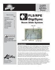
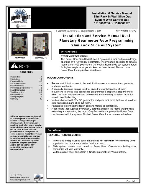
<strong>Installation</strong> & <strong>Service</strong> <strong>Manual</strong><br />
Slim Rack In Wall Slide Out<br />
System With Control Box<br />
1510000236 or 1510000276<br />
© Copyright LCI/<strong>Power</strong> <strong>Gear</strong> Issued: December 2014 #3010002813, Rev. 0G<br />
<strong>Installation</strong> <strong>and</strong> <strong>Service</strong> <strong>Manual</strong> <strong>Dual</strong><br />
<strong>Planetary</strong> <strong>Gear</strong> motor Auto Programming<br />
Slim Rack Slide out System<br />
Introduction<br />
1510000236 1510000276<br />
NOTE<br />
CONTENTS<br />
SYSTEM DESCRIPTION:<br />
The <strong>Power</strong> <strong>Gear</strong> Slim Rack Slideout System is a rack <strong>and</strong> pinion design<br />
operated by a 12 Volt DC gearmotor. The system is designed to actuate<br />
rooms up to 1500 pounds <strong>and</strong> 30” stroke. Room slide out systems rated<br />
for higher weight or longer strokes can be obtained. Please contact<br />
<strong>Power</strong> <strong>Gear</strong> for application assistance.<br />
Introduction 1<br />
<strong>Installation</strong> 1-3<br />
Program Mode 4-5<br />
<strong>Installation</strong> Issues 5<br />
Operation Mode 5-6<br />
Preventative Maintenance 6<br />
Fault Diagnostics 6-7<br />
Troubleshooting 6-7<br />
Override Mode 7-8<br />
Wiring Diagram 9<br />
Warranty 10<br />
Slide out systems are engineered<br />
to provide years of trouble free<br />
service. Changes to weight,<br />
stroke, weight distribution, rail<br />
position, controller, power supply,<br />
seals, slide toppers, ramps, rollers,<br />
etc. all have an effect on the<br />
performance of the system. In<br />
order to secure warranty coverage,<br />
each new application or changes<br />
to existing applications must be<br />
audited <strong>and</strong> approved by <strong>Power</strong><br />
<strong>Gear</strong> with a signed document.<br />
Audits can be arranged by<br />
contacting your account<br />
representative.<br />
MAJOR COMPONENTS:<br />
• Rocker switch that mounts to the wall. It allows room movement <strong>and</strong> provides<br />
end user feedback.<br />
• A specially designed control box that gives the user full control of room<br />
movement, in or out. The control has programmable stops that stop the motor<br />
when the room is fully extended or retracted <strong>and</strong> the ability to detect faults for<br />
ease in troubleshooting.<br />
• Vertical channel with 12V DC gearmotor <strong>and</strong> gear rack arms that mount into the<br />
side wall opening <strong>and</strong> slide out room.<br />
• Harnesses to connect the touch pad <strong>and</strong> motors to control box.<br />
• Floor rollers (not supplied by <strong>Power</strong> <strong>Gear</strong>) that support the rooms weight while<br />
extending <strong>and</strong> retracting the room. Only floor rollers approved by <strong>Power</strong> <strong>Gear</strong><br />
can be used with the system. Contact <strong>Power</strong> <strong>Gear</strong> for recommended rollers.<br />
<strong>Installation</strong><br />
GENERAL REQUIREMENTS:<br />
• <strong>Power</strong> <strong>and</strong> wiring must be such that there is not less than 10.5 running volts<br />
supplied at the motor leads under maximum load.<br />
• Slide system controls must come from <strong>Power</strong> <strong>Gear</strong>. Controls supplied by other<br />
companies will void warranty.<br />
• Voltage supply must come from a 12VDC automotive/RV type battery.<br />
1217 E. 7 th St.<br />
Mishawaka, IN 46544<br />
www.powergearus.com<br />
Page 1 of 11
3010002813 Rev. 0G <strong>Installation</strong> <strong>and</strong> <strong>Service</strong> <strong>Manual</strong> Slim Rack Slide Out System<br />
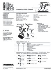
Harness, Control<br />
to Rocker Switch<br />
Rocker Switch<br />
Vertical Channel <strong>and</strong> Mounting Flange<br />
Harness,<br />
Control to<br />
Motor<br />
Vertical Channel Assembly<br />
Control Box<br />
End Brackets<br />
Figure 1<br />
<strong>Power</strong> <strong>Gear</strong> Slim Rack® Slideout System Components<br />
<strong>Installation</strong> (Continued)<br />
Mechanical Components:<br />
1. Install <strong>Power</strong> <strong>Gear</strong> approved floor rollers. Consult roller manufacturer for proper installation<br />
procedures <strong>and</strong> location.<br />
2. For sealing the screws used to attach end brackets, <strong>Power</strong> <strong>Gear</strong> recommends RTV silicone, rubber<br />
gasket, or closed cell foam gasket. DO NOT use any type of sealant putty as this can intrude into<br />
the mechanism <strong>and</strong> possibly cause the system to malfunction.<br />
Figure 3 moving assy into<br />
position<br />
Figure 4<br />
End<br />
Bracket<br />
<strong>Gear</strong><br />
Rack<br />
Figure 4a<br />
Install Fixture<br />
OPTION A - WITH INSTALLATION FIXTURE:<br />
1a. An <strong>Installation</strong> Fixture (FIG 4a) is used to maintain even spacing between the upper <strong>and</strong> lower<br />
gear rack arms <strong>and</strong> the location of the end brackets. Even spacing between the gear rack arms<br />
<strong>and</strong> the location of the end brackets is critical for proper operation of the slide out. <strong>Installation</strong><br />
Fixtures are reusable from system to system. <strong>Installation</strong> Fixtures are not supplied with system<br />
<strong>and</strong> must be purchased from <strong>Power</strong> <strong>Gear</strong> to aid in assembly <strong>and</strong> reduce installation time.<br />
2a. Place the slide out mechanism into the installation fixture (FIG 4a) <strong>and</strong> bring the assembly up<br />
to the side of the slide room box (FIG 3), making sure that the end brackets are flush to the wall<br />
<strong>and</strong> up against the outer flange of the room. Be sure to keep the gear rack <strong>and</strong> the end<br />
brackets level when mounting (FIG 4).<br />
3a. Secure each end bracket with four (4) flat head #10 screws (FIG 6, pg 3). A flat head screw<br />
must be used.<br />
4a. Repeat steps 1a-4a for the other side of the slide out room. Proceed to step #3.<br />
OPTION B - WITH DRILL FIXTURE:<br />
1b. A Drill Fixture (FIG 6a, page 3) is used to pre-drill the mounting holes for the end brackets <strong>and</strong><br />
maintain even spacing between the upper <strong>and</strong> lower gear rack arms. Even spacing between<br />
the gear rack arms <strong>and</strong> the location of the end brackets is critical for proper operation of the<br />
slide out. Drill Fixtures are reusable from system to system. Drill Fixtures are not supplied with<br />
system <strong>and</strong> must be purchased from <strong>Power</strong> <strong>Gear</strong> to aid in assembly <strong>and</strong> reduce installation<br />
time.<br />
2b. Position the drill fixture so that the bottom flange of the fixture is pulled up against the bottom of<br />
the room.<br />
3b. Move the drill fixture out so that it is up flush against the outer room flange.<br />
4b. Drill all 16 holes (4 per end bracket) with a #25 drill bit.<br />
5b. Place the slide mechanism up to the side of the room <strong>and</strong> secure end brackets with flat head<br />
#10 screws (FIG 6, pg 3). A flat head screw must be used.<br />
6b. Repeat steps 1b-6b for the other side of the slide out room. Proceed to step #3.<br />
Continued:<br />
3. Lift the slide room box into coach opening <strong>and</strong> push in until mounting flange meets exterior wall.<br />
NOTE: In some applications <strong>and</strong> interior mounting flange may be used. Install mounting flange once<br />
C-channel assemblies are properly installed.<br />
4. Verify that the weight of the room is supported by the floor rollers <strong>and</strong> not the slide out mechanism<br />
(FIGURE 5). NOTE: If the room is not completely supported by the floor rollers, you will hear a slight<br />
“popping” sound as the room settles on to the rollers. This is normal, <strong>and</strong> there is nothing wrong with<br />
the system or the install.<br />
5. Secure the mounting flanges to the unit’s side wall (FIGURE 6, page 3).<br />
Alternate <strong>Installation</strong> instructions for VERTICAL CHANNEL ASSEMBLIES with two flanges:<br />
After steps 1-5 above are complete, it will be necessary to remove the inner flange (FIGURE 7, page 3)<br />
from each side of the VERTICAL CHANNEL ASSEMBLIES before lifting the room into position. Once<br />
room is in position, reinstall removed flanges.<br />
<strong>Installation</strong> of the VERTICAL CHANNEL ASSEMBLY is now complete.<br />
Page 2 of 11
3010002813 Rev. 0G <strong>Installation</strong> <strong>and</strong> <strong>Service</strong> <strong>Manual</strong> Slim Rack Slide Out System<br />
<strong>Installation</strong> (Continued)<br />
Left<br />
Right<br />
Floor Roller (not supplied)<br />
Figure 5<br />
Figure 6a<br />
Drill Fixture<br />
Figure 7<br />
Figure 6<br />
Wire Gauge Maximum Length<br />
16 10 feet<br />
14 15 feet<br />
12 25 feet<br />
10 40 feet<br />
Wire must be sized so that a<br />
minimum of 12.5 VDC is measured at<br />
the control while under a load.<br />
Figure 8 Information is given as<br />
reference only<br />
Figure 9A Park Brake Dip Switch<br />
on Control Box<br />
Electrical Components:<br />
1. Mount the CONTROL BOX (FIGURE 1, page 1) in a clean <strong>and</strong> dry, weather tight location<br />
that will keep it from being damaged, but is easily accessible for service. The control is<br />
not waterproof.<br />
2. Determine location to mount the rocker switch (FIGURE 12, page 4). Location needs to<br />
be in view of slideout room <strong>and</strong> have minimum depth of 1” inside the wall.<br />
3. Route <strong>and</strong> attach the harness to where the rocker switch will be mounted, <strong>and</strong> mount the<br />
rocker switch with two (2) screws.<br />
4. Label the motor leads at both ends to aid in connections at the control box <strong>and</strong> motors.<br />
Route the motor/sensor harnesses from the slideout room motors to the control box.<br />
5. Route the park brake input harness from the park brake signal source to the control box<br />
or to bypass the park brake input signal, move the dip switch at the park brake connector<br />
on the control box to the left (FIGURE 9A).<br />
Note: It is important that the slideout motors be plugged in to the proper receptacle at the<br />
control box. Please see the FIGURE 9 below for proper slide out motor designation. Failure to<br />
properly connect the motors to the control will result in problems for future troubleshooting.<br />
(The control will identify the incorrect motor during a fault).<br />
5. Route <strong>and</strong> attach the proper gauge wire from the control to the 12V DC battery. See<br />
FIGURE 8 to the left. It is recommended that this circuit be protected with a 30 amp fuse.<br />
<strong>Installation</strong> of the In Wall Slideout is now complete. You are now ready to operate the slideout<br />
room.<br />
M1 (Motor 1)<br />
Road-side of Motor home<br />
M2 (Motor 2)<br />
Curb-side of Motor home<br />
M2 (Motor 2) M1 (Motor 1)<br />
Figure 9<br />
Proper designation of motors as M1 or M2<br />
Page 3 of 11
3010002813 Rev. 0G <strong>Installation</strong> <strong>and</strong> <strong>Service</strong> <strong>Manual</strong> Slim Rack Slide Out System<br />
WARNING<br />
• Always make sure that the<br />
slideout room path is clear of<br />
people <strong>and</strong> objects before <strong>and</strong><br />
during operation of the slideout<br />
room.<br />
• Always keep away from the slide<br />
rails when the room is being<br />
operated. The gear assembly<br />
may pinch or catch on loose<br />
clothing causing personal injury.<br />
NOTE<br />
The switch will need to<br />
be depressed <strong>and</strong> held<br />
down for 2 seconds<br />
after the room stops<br />
moving to correctly set<br />
the stop locations. This<br />
applies to both the IN<br />
stop (retracted) <strong>and</strong><br />
OUT stop (extended).<br />
Failure to do so will<br />
cause the stops to NOT<br />
be set.<br />
Program Mode<br />
Use this procedure to SET the IN <strong>and</strong> OUT stops.<br />
Note: To correctly set the stops. First fully retract the room to set the IN stop <strong>and</strong> then fully<br />
extend the room to set the OUT stop. The switch will need to be depressed <strong>and</strong> held for<br />
2 seconds after the room stops moving. Failure to do so will cause the stops to NOT be<br />
set.<br />
1. Press <strong>and</strong> hold the IN button on the wall rocker switch (FIGURE 12).<br />
2. Move the room to the fully retracted position. Press <strong>and</strong> hold the IN button for 2 seconds<br />
after the room stops moving. Release the wall switch.<br />
3. Visually inspect the room seal to make certain the room is fully retracted. If it is not,<br />
push <strong>and</strong> hold the IN button until fully retracted. This procedure may need to be<br />
repeated until both sides of the slide out are fully retracted.<br />
4. You are now ready to set the OUT stop.<br />
5. Press <strong>and</strong> hold the OUT button on the wall rocker switch (FIGURE 12).<br />
6. Move the room to the fully extended position. Press <strong>and</strong> hold the OUT switch for 2<br />
seconds after the room stops moving. Release the wall switch.<br />
7. Visually inspect the room seal to make certain the room is fully extended. If it is not,<br />
push <strong>and</strong> hold the OUT button until fully extended. This procedure may need to be<br />
repeated until both sides of the slide out are fully extended.<br />
Figure 12 Rocker Switch 1510000240<br />
<strong>Installation</strong> Issues<br />
The control box is equipped to help troubleshoot the system during installation. Count the<br />
number of LED flashes <strong>and</strong> refer to the FAULT DIAGNOSTICS/TROUBLESHOOTING<br />
section starting on page 6 of this manual or on the label of the control box.<br />
Note: It is important that the slide out motors be plugged in to the proper receptacle at the<br />
control box. Please see the FIGURE 9 for proper slide out motor designation. Failure to<br />
properly connect the motors to the control will result in problems for future troubleshooting.<br />
(The control will identify the incorrect motor during a fault).<br />
If you are still having difficulties programming the system (<strong>and</strong> prior to replacing the control),<br />
verify that the system has been wired correctly <strong>and</strong> that the IN stop location was<br />
programmed before the OUT stop location. See FIGURE 9, page 3 for proper connection of<br />
the motors to the slideout control.<br />
1217 E. 7 th St.<br />
Mishawaka, IN 46544<br />
www.powergearus.com<br />
Page 4 of 11
3010002813 Rev. 0G <strong>Installation</strong> <strong>and</strong> <strong>Service</strong> <strong>Manual</strong> Slim Rack Slide Out System<br />
WARNING<br />
• Always make sure that the<br />
slideout room path is clear<br />
of people <strong>and</strong> objects<br />
before <strong>and</strong> during<br />
operation of the slideout<br />
room.<br />
• Always keep away from<br />
the slide rails when the<br />
room is being operated.<br />
The gear assembly may<br />
pinch or catch on loose<br />
clothing causing personal<br />
injury.<br />
Operation Mode<br />
Prior to moving the slide out room:<br />
• Make sure the engine or generator is running to ensure ample voltage is being supplied<br />
to the slide out control box.<br />
• Set the parking brake, if applicable.<br />
Extending the room:<br />
1. The engine or generator must be running, or coach is plugged into shore power.<br />
2. Transmission must be in park or neutral (if applicable).<br />
3. Set the park brake (if applicable) <strong>and</strong> level the unit.<br />
4. If equipped, remove the transit bars.<br />
5. If equipped, turn “on” the on/off switch or key.<br />
6. Press <strong>and</strong> hold the OUT button (FIGURE 12, page 4). There will be a slight delay<br />
before the room will begin to move, this is normal.<br />
7. Release the button when the room is fully extended <strong>and</strong> stops moving.<br />
8. If equipped, turn “off” the on/off switch or key.<br />
Retracting the room:<br />
1. The engine or generator must be running, or plugged into shore power.<br />
2. Transmission must be in park or neutral (if applicable).<br />
3. Set the park brake (if applicable) <strong>and</strong> level the unit.<br />
4. If equipped, turn “on” the on/off switch or key.<br />
5. Press <strong>and</strong> hold the IN button (FIGURE 12, page 4). There will be a slight delay<br />
before the room will begin to move, this is normal.<br />
6. Release the button when the room is fully retracted <strong>and</strong> stops moving.<br />
7. If equipped, turn “off” the on/off switch or key.<br />
8. If equipped, install the transit bars.<br />
Preventative Maintenance<br />
Your <strong>Power</strong> <strong>Gear</strong> slideout system has been designed to require very little maintenance. To<br />
ensure the long life of your slideout system, read <strong>and</strong> follow these few simple procedures:<br />
• When the room is extended, visually inspect the slide rail assemblies. Check for excess<br />
build up of dirt or other foreign material; remove any debris items that may be present.<br />
• If the system squeaks or makes any noises, blow out any debris from the gear rack arms<br />
<strong>and</strong> apply a dry lubricant to prevent <strong>and</strong>/or stop squeaking.<br />
If you have any problems or questions, see the contact tab on<br />
our website at www.powergearus.com<br />
Fault Diagnostics/Troubleshooting<br />
Figure 12A Green <strong>and</strong> Red LED's<br />
on control box<br />
1217 E. 7 th St.<br />
Mishawaka, IN 46544<br />
www.powergearus.com<br />
This control has the ability to detect <strong>and</strong> display several faults. When a fault is detected,<br />
the room movement may stop <strong>and</strong> two (2) different LED’s on the control box will flash in a<br />
pattern.<br />
• The FAULT CODE LED (FIGURE 12, page 4) on the rocker switch will flash RED<br />
a number of times corresponding to the number of red flashes on the control box<br />
(FIGURE 12A). Refer to the TROUBLESHOOTING chart on page 6 to best<br />
determine what caused the fault.<br />
• The MOTOR LED (FIGURE 12A) on the control box will flash GREEN a number<br />
of times corresponding to which motor had the associated fault.<br />
• For example: if you are seeing two (2) GREEN flashes <strong>and</strong> four (4) RED<br />
flashes, it means that there is a motor fault on motor 2.<br />
Note: For major faults, the control will automatically enter "Emergency Jog" mode when<br />
motor movement is not detected by the control box in either direction during room<br />
actuation. When in "Emergency Jog" mode, the control will jog both motors in the<br />
direction the rocker switch is pressed (IN or OUT). The rocker switch may need to be<br />
pressed multiple times to fully retract or extend the room. Take the unit to an O.E.M<br />
authorized dealer for service. NOTE: The control box will return to normal operation<br />
mode after 5 minutes of inactivity or by cycling power to the control box.<br />
Page 5 of 11
3010002813 Rev. 0G <strong>Installation</strong> <strong>and</strong> <strong>Service</strong> <strong>Manual</strong> Slim Rack Slide Out System<br />
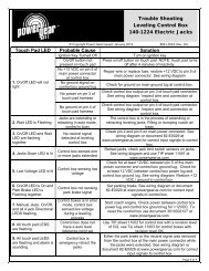
FIGURE 13<br />
Fault Code<br />
Number of Flashes<br />
Green Flash Red Flash<br />
Fault<br />
Type<br />
1 1 Minor Park Brake not set<br />
Fault Diagnostics/Troubleshooting (continued)<br />
FAULT CODES<br />
Description Possible Cause Possible Solutions<br />
• Park Brake not set (if<br />
applicable)<br />
• Ground signal lost at park<br />
brake receptacle at control<br />
box.<br />
• Set parking brake (if applicable).<br />
• Check for continuity to ground<br />
on wire plugged into park brake<br />
receptacle at control box.<br />
1 2 Minor Low Voltage<br />
1 4 Major Motor 1 Fault<br />
2 4 Major Motor 2 Fault<br />
1 6 Minor High Voltage<br />
Incoming voltage to control is<br />
below 12.0 VDC. The room will<br />
NOT move if the voltage is 10.5<br />
VDC or below.<br />
• Bad wire connection<br />
• Bad motor<br />
• Bad wire connection<br />
• Bad motor<br />
Supply voltage to control<br />
box is 17 VDC or greater.<br />
Start vehicle, generator, or ensure<br />
plugged into shore power. Check 2-<br />
pin power connector at control box at<br />
BATT + <strong>and</strong> GND -. Consult<br />
manufacturer of unit charging system<br />
for troubleshooting assistance.<br />
• Refer to TIP Sheet 82-S0533 for<br />
troubleshooting.*<br />
Consult manufacturer of unit charging<br />
system for troubleshooting<br />
assistance.<br />
Override Mode<br />
*This tip sheet <strong>and</strong> other<br />
updated troubleshooting<br />
information can be found on<br />
our website at<br />
www.powergearus.com.<br />
# of RED<br />
flashes<br />
Figure 14<br />
1217 E. 7 th St.<br />
Mishawaka, IN 46544<br />
www.powergearus.com<br />
# of GREEN<br />
flashes<br />
In the event of component failure or loss of system power, your slideout can be manually overridden <strong>and</strong><br />
retracted for travel.<br />
Note: At any time during the override procedure, the unit will exit this mode if the room has not been<br />
moved for five (5) minute.<br />
Note: For major faults, only 1510000236 control will automatically enter "Emergency Jog"<br />
mode when motor movement is not detected by the control box in either direction during room<br />
actuation. When in "Emergency Jog" mode, the control will jog both motors in the direction<br />
the rocker switch is pressed (IN or OUT). The rocker switch may need to be pressed multiple<br />
times to fully retract or extend the room. Take the unit to an O.E.M authorized dealer for<br />
service. NOTE: The control box will return to normal operation mode after 5 minutes of<br />
inactivity or by cycling power to the control box.<br />
Use T.I.P Sheet 82-S0544 to reset control box 1510000276<br />
MANUAL EMERGENCY RETRACT MODE<br />
In the event that power is lost to the slide out motor(s) the room can be manually retracted by<br />
following these steps:<br />
1. You will need to gain access from either the inside or outside (which ever is more<br />
convenient) of the coach to the VERTICAL CHANNEL assembly. The motors are<br />
currently located at the top of channel.<br />
2. If applicable, remove the top screw from the bulb seal at the top of the VERTICAL<br />
CHANNEL (FIGURE 15).<br />
3. Pull down the bulb seal <strong>and</strong> remove the motor cover (FIGURE 16). The motor cover may<br />
stick to the bulb seal.<br />
4. Using a pick tool, remove the end of the retaining spring from the motor spring clip<br />
(FIGURE 17).<br />
5. Unplug the motor from the harness <strong>and</strong> remove the motor by lifting it up <strong>and</strong> out.<br />
6. Repeat steps 1-4 for the other side.<br />
7. Push the room into the retracted position.<br />
8. Secure the room in place by either re-installing the motors (making sure the end of the<br />
retaining spring is rehooked to the motor spring clip <strong>and</strong> the motor retainer is fully<br />
engaged) or using a travel lock, 2 x 4 (cut to size) etc.<br />
9. Have the slide out room serviced by the O.E.M. authorized dealer as soon as possible.<br />
Do not operate room until service is complete as damage to the room may result.<br />
Page 6 of 11
3010002813 Rev. 0G <strong>Installation</strong> <strong>and</strong> <strong>Service</strong> <strong>Manual</strong> Slim Rack Slide Out System<br />
WARNING<br />
• Always make sure that the<br />
slideout room path is clear<br />
of people <strong>and</strong> objects<br />
before <strong>and</strong> during<br />
operation of the slideout<br />
room.<br />
• Always keep away from<br />
the slide rails when the<br />
room is being operated.<br />
The gear assembly may<br />
pinch or catch on loose<br />
clothing causing personal<br />
injury.<br />
Override Mode (continued)<br />
Note: For major faults, the control will automatically enter "Emergency Jog" mode when<br />
motor movement is not detected by the control box in either direction during room actuation.<br />
When in "Emergency Jog" mode, the control will jog both motors in the direction the rocker<br />
switch is pressed (IN or OUT). The rocker switch may need to be pressed multiple times to<br />
fully retract or extend the room. Take the unit to an O.E.M authorized dealer for service.<br />
NOTE: The control box will return to normal operation mode after 5 minutes of<br />
inactivity or by cycling power to the control box.<br />
Remove Screw<br />
Figure 15 Removing the bulb seal screw<br />
Motor<br />
Motor<br />
Cover<br />
Motor<br />
Spring<br />
Clip<br />
Figure 16<br />
Figure 17<br />
Note: It may be possible to manually retract the room by accessing the ½” square drive tube<br />
at the bottom of each vertical channel assembly. This will only be possible if there is access<br />
to this area.<br />
Figure 18 8-point star socket<br />
1. You will first need to follow steps 1-6 as detailed above.<br />
2. Using a ½” 8-point star socket (FIGURE 18) <strong>and</strong> alternating from one side to the<br />
other, turn the ½” square drive tube to bring the room in. A 15 mm 12-point socket is<br />
an option if the ½” 8-point star socket is not available. Use caution, as the 15 mm<br />
12-point socket does not fit as snug as the ½” 8-point socket.<br />
3. When the room is retracted, secure the room per step 8 shown on page 6.<br />
4. Have the slide out room serviced by a dealer as soon as possible. Do not operate<br />
room until service is complete as damage to the room may result.<br />
1217 E. 7 th St.<br />
Mishawaka, IN 46544<br />
www.powergearus.com<br />
Page 7 of 11
3010002679 Rev 0C Owner’s <strong>Manual</strong> In Wall Slide Out System<br />
Override Modes (continued)<br />
Note: It may also be possible to manually retract the room by using a ratchet <strong>and</strong> socket<br />
attached to the end of the coupler (FIGURE 18).<br />
1. You will first need to follow steps 1-6 under the <strong>Manual</strong> Retract Mode section to remove<br />
the motor.<br />
2. Place a socket wrench with a 3” extension <strong>and</strong> 5/8” deep well socket (FIGURE 19)<br />
through the motor access opening <strong>and</strong> seat the socket onto the coupler. One man<br />
alternating from side to side of the room is able to retract a 1500 lbs. room with or<br />
without a ramp.<br />
Note: 1 person per side of the room (2 total) with ratchet <strong>and</strong> socket will expedite the<br />
process. Room moves approx.. ¼” for every 30-40 degree turn of the wrench.<br />
3. Secure the room in place by either re-installing the motors (making sure the end of the<br />
retaining spring is re-hooked to the motor spring clip (FIGURE 17) or torque the motor<br />
retaining screw to 40 in lbs. (FIGURE 16) <strong>and</strong> the motor retainer is fully engaged) or<br />
using a travel lock, 2 x 4 (cut to size), etc.<br />
4. Have the slide out room serviced by an O.E.M.authorized dealer as soon as possible.<br />
Do not operate room until service is complete as damage to the room may result.<br />
Figure 19 Ratchet with 3/8” extension <strong>and</strong> 5/8” deep well socket<br />
Figure 18 Coupler<br />
Figure 20<br />
Ratchet inside motor access with socket on coupler<br />
1217 E. 7 th St.<br />
Mishawaka, IN 46544<br />
www.powergearus.com<br />
Page 8 of 11
3010002813 Rev. 0G <strong>Installation</strong> <strong>and</strong> <strong>Service</strong> <strong>Manual</strong> Slim Rack Slide Out System<br />
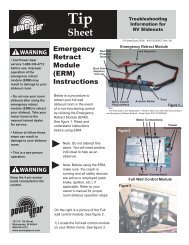
Wiring Information for Control Box 1510000276<br />
1510000238-XX Rocker Switch Harness<br />
Figure 21<br />
Back<br />
View<br />
Figure 23<br />
1510000233 <strong>Power</strong> Harness<br />
Figure 24<br />
1510000277 control to motor harness<br />
Parking<br />
brake<br />
connector<br />
Park Brake<br />
Dip Switch<br />
Figure 22 Control Box 1510000276<br />
Figure 25<br />
1510000194 control to motor harness<br />
Figure 26 Park Brake Harness 1510000237-XX<br />
Page 9 of 11
3010002813 Rev. 0G <strong>Installation</strong> <strong>and</strong> <strong>Service</strong> <strong>Manual</strong> Slim Rack Slide Out System<br />
Wiring Information for Control Box 1510000236<br />
Note: See FIGURE 23 below<br />
for rocker switch reference to<br />
pins 1, 2, 3 <strong>and</strong> 4.<br />
Figure 27<br />
1510000238-XX Rocker Switch Harness<br />
Figure 29<br />
1510000233 <strong>Power</strong> Harness<br />
Figure 30<br />
1510000194 control to motor harness<br />
Figure 28 Control Box 1510000236<br />
Figure 31 Park Brake Harness 1510000237-XX<br />
Figure 32 Rocker Switch 1510000240<br />
Reference of pins 1, 2, 3 <strong>and</strong> 4 from FIGURE 19<br />
above.<br />
Page 10 of 11
3010002813 Rev. 0G <strong>Installation</strong> <strong>and</strong> <strong>Service</strong> <strong>Manual</strong> Slim Rack Slide Out System<br />
ADDITIONAL REFERENCE PUBLICATIONS LOCATED AT<br />
WWW.POWERGEARUS.COM<br />
Document #<br />
Description<br />
3010002814 Owner's <strong>Manual</strong> Slim Rack In Wall Slide out System<br />
82-S0533 Trouble Shooting Slide Out Control Box 1510000236 or 1510000276 For In-Wall Slim Rack Systems<br />
82-S0534 Encoder Test 1 <strong>Dual</strong> <strong>Planetary</strong> <strong>Gear</strong> Motor Sync with Control Box 1510000236 or 1510000276<br />
82-S0535 Encoder Test 2 <strong>Dual</strong> <strong>Planetary</strong> <strong>Gear</strong> Motor Sync with Control Box 1510000236 or 1510000276<br />
82-S0544 1510000276 Slide Out Control Box Reset Procedure<br />
<strong>Power</strong> <strong>Gear</strong> Limited Warranty<br />
<strong>Power</strong> <strong>Gear</strong> Limited Warranty Policy<br />
(Original equipment)<br />
<strong>Power</strong> <strong>Gear</strong> warrants its manufacturer installed <strong>Power</strong> <strong>Gear</strong> <strong>and</strong> Kwikee br<strong>and</strong> products to be free<br />
of material <strong>and</strong> workmanship defects for two (2) years from the date of the original sale of the motor<br />
vehicle/recreation vehicle (RV) in which they are installed, provided that these products are installed<br />
<strong>and</strong> operated according to the purpose for which they were intended, designed <strong>and</strong> specified. This<br />
warranty does not cover product that is incorrectly installed, or upon examination has been misused<br />
or abused by the vehicle owner.<br />
Warranty coverage includes:<br />
• Repair or replacement of the defective component(s) of the malfunctioning system. Entire<br />
systems are not replaced unless either the faulty component is not replaceable or all<br />
components comprising the system are defective.<br />
• Labor costs for the diagnosis <strong>and</strong> repair work associated with the repair or replacement of<br />
the defective component(s) by a licensed servicing center.<br />
This warranty does not include payment or reimbursement of:<br />
• Normal system maintenance <strong>and</strong> preventive maintenance.<br />
• Mobile service or towing expenses related to field repairs <strong>and</strong>/or the transportation of the<br />
vehicle to a repair facility.<br />
• Living or travel related expenses incurred in the repair of the vehicle.<br />
By filing a warranty claim in accordance with <strong>Power</strong> <strong>Gear</strong>’s Warranty Administration Procedure,<br />
service providers agree that the replacement part(s) will be provided to the vehicle owner at no cost<br />
<strong>and</strong> that the total labor charges for the completion of warranty repairs will be billed to <strong>Power</strong> <strong>Gear</strong>.<br />
Accordingly, under no circumstances will <strong>Power</strong> <strong>Gear</strong> reimburse the vehicle owner directly for costs<br />
covered under this warranty policy.<br />
Warranty coverage runs concurrently with any vehicle warranty period provided by the<br />
manufacturer, <strong>and</strong> is transfer-able to subsequent owners. Proof of original date of purchase of<br />
vehicle, <strong>and</strong> if applicable subsequent owner’s proof of purchase, is required to confirm coverage.<br />
<strong>Power</strong> <strong>Gear</strong> reserves the right to change the terms of our warranty policy at any time. For the most<br />
current information on product warranty <strong>and</strong> our warranty claim procedure, visit our website at<br />
www.powergearus.com.<br />
Page 11 of 11