HYDRAULIC LEVELING SYSTEMS OPERATIONS ... - Power Gear
HYDRAULIC LEVELING SYSTEMS OPERATIONS ... - Power Gear
HYDRAULIC LEVELING SYSTEMS OPERATIONS ... - Power Gear

You also want an ePaper? Increase the reach of your titles
YUMPU automatically turns print PDFs into web optimized ePapers that Google loves.
<strong>HYDRAULIC</strong> <strong>LEVELING</strong> <strong>SYSTEMS</strong><br />
<strong>OPERATIONS</strong> MANUAL<br />
(For systems with touch pad part number 500089, 500105,<br />
500210, 500456, 500535 or no number at all)<br />
Visit us on the web at www.powergearus.com<br />
82-L0040-01<br />
Rev. 1
WARNING<br />
• DO NOT USE THE POWER GEAR <strong>HYDRAULIC</strong> <strong>LEVELING</strong> SYSTEM (OR AIR<br />
SUSPENSION) TO SUPPORT VEHICLE WHILE UNDER COACH OR<br />
CHANGING TIRES. THE <strong>HYDRAULIC</strong> <strong>LEVELING</strong> SYSTEM IS DESIGNED AS<br />
A ‘<strong>LEVELING</strong>’ SYSTEM ONLY. TIRE REPAIRS SHOULD BE PERFORMED BY<br />
A TRAINED PROFESSIONAL. ATTEMPTS TO CHANGE TIRES WHILE<br />
SUPPORTING THE VEHICLE WITH THE <strong>HYDRAULIC</strong> SYSTEM COULD<br />
RESULT IN DAMAGE TO THE MOTOR HOME AND/OR CAUSE SERIOUS<br />
INJURY OR EVEN DEATH.<br />
• KEEP PEOPLE CLEAR OF COACH WHILE <strong>LEVELING</strong> SYSTEM IS IN USE.<br />
• NEVER LIFT THE WHEELS OFF THE GROUND TO LEVEL THE COACH.<br />
DOING SO MAY CREATE AN UNSTABLE CONDITION.<br />
• NEVER EXPOSE HANDS OR OTHER PARTS OF THE BODY NEAR<br />
<strong>HYDRAULIC</strong> LEAKS. HIGH PRESSURE OIL LEAKS MAY CUT AND<br />
PENETRATE THE SKIN CAUSING SERIOUS INJURY.<br />
CAUTION - PARK THE COACH ON A REASONABLY SOLID SURFACE OR THE<br />
JACKS MAY SINK INTO GROUND. ON SOFT SURFACES, USE LOAD<br />
DISTRIBUTION PADS UNDER EACH JACK.<br />
CAUTION - CHECK THAT POTENTIAL JACK CONTACT LOCATIONS ARE CLEAR<br />
OF OBSTRUCTIONS OR DEPRESSIONS BEFORE OPERATION.<br />
BEFORE YOU OPERATE THE SYSTEM:<br />
The leveling system shall only be operated under the following conditions:<br />
1. The coach is parked on a reasonably level surface.<br />
2. The coach "PARKING BRAKE" is engaged.<br />
3. The coach transmission should be in the neutral or park position.<br />
4. The ignition is in the run position, or engine is running.
SYSTEM DESCRIPTION<br />
Please read and study the operating manual before you operate the leveling system.<br />
SYSTEM DESCRIPTION - The <strong>Power</strong> <strong>Gear</strong> electro-hydraulic leveling system consists of the<br />
following major components:<br />
(A) Spring return jacks rated at a lifting capacity appropriate for your coach. Each jack has a large<br />
10" diameter (78.5 square inch) shoe for maximum surface area on soft surfaces.<br />
(B) Each jack is powered from a central 12VDC motor/pump assembly, which also includes the<br />
hydraulic oil reservoir tank, control valve manifold, and solenoid valves.<br />
(C) The control system located in the coach controls the system. There are 2 different control<br />
systems possible:<br />
• A Manual control with bubble level.<br />
• A Semi-automatic control, with internal leveling sensor<br />
RECOMMENDED <strong>HYDRAULIC</strong> FLUIDS FOR YOUR POWER GEAR <strong>LEVELING</strong><br />
SYSTEM<br />
The fluids listed here are acceptable to use in your pump assembly. Contact coach manufacturer or<br />
selling dealer for information about what specific fluid was installed in your system.<br />
Please consult factory before using any other fluids.<br />
In most applications,<br />
• Type A automatic transmission fluid (ATF, Dexron III, etc.,) will work satisfactorily.<br />
• Mercon V is also recommended as an alternative fluid for <strong>Power</strong> <strong>Gear</strong> leveling systems<br />
operating in environments with large temperature swings<br />
Operating in cold temperatures (less than -10° F) may cause the jacks may extend and retract<br />
slowly. For cold weather operation, fluid specially-formulated for low temperatures may be desirable,<br />
• Mobil DTE 11M, Texaco Rando HDZ-15HVI, Kendall Hyden Glacial Blu, or any Mil. Spec.<br />
H5606 hydraulic fluids are recommended for cold weather operation.
PREVENTATIVE MAINTENANCE PROCEDURES<br />
WARNING:<br />
Your coach should be supported at both front and rear axles with jack stands before<br />
working underneath, failure to do so may result in personal injury or death.<br />
1. Check the fluid level every month. Fill the reservoir with the jacks in the fully retracted<br />
position. On 1998 - PRESENT model year coaches, the fluid should be within 1/4 inch of<br />
the fill port lip and checked only with all jacks retracted. On pre-1998 model year coaches<br />
the fluid level should be approximately 1/8 inch on the dipstick and checked only with all<br />
jacks retracted.<br />
2. Change fluid every 24 months.<br />
3. Inspect and clean all hydraulic pump electrical connections every 12 months.<br />
4. Remove dirt and road debris from jacks as needed.<br />
5. If jacks are down for extended periods, it is recommended to spray exposed chrome<br />
rods with a silicone lubricant every seven days for protection. If your coach is located in<br />
a salty environment (within 60 miles of coastal areas), it is recommended to spray the rods<br />
every 2 to 3 days.<br />
6. Jacks equipped with grease fittings at the bottom of the cylinder should be greased<br />
with a light weight lithium grease using a hand pump style grease gun only. 2 or 3<br />
pumps should be sufficient for 20-30 uses.
MANUAL SYSTEM <strong>LEVELING</strong> PROCEDURES FOR COACHES WITH THE<br />
FOLLOWING TOUCH PADS<br />
SELECTING A SITE<br />
When the coach is parked on an excessive slope the leveling requirements may exceed the jack<br />
lift stroke capability. If the coach is parked on an excessive slope, the coach should be moved to a<br />
more level surface before the leveling system is deployed.
1. Push "ON/OFF" pad on control panel. The system is now operational and the "ON/OFF" light<br />
will be lit. If "ON/OFF" light is not lit, see “BEFORE YOU OPERATE THE SYSTEM”<br />
conditions on page L4.<br />
2. Push “FRONT JACKS” button until the front of the coach rises at least 3 “. This is important<br />
and necessary to allow the coach to pivot when leveling side to side. If there is insufficient<br />
jack stroke to lift the front of the coach at least 3 inches the coach will have to be moved to an<br />
area with less front to back slope.<br />
3. Push “REAR JACKS” button until jacks contact the ground.<br />
4. If bubble is towards front of coach push “REAR JACKS” button, If bubble is towards rear of<br />
coach push “FRONT JACKS” button. Keep button depressed until bubble is centered in vial<br />
from front to back, then release.<br />
5. If bubble is towards left of coach push “RIGHT JACKS” button, If bubble is towards right of<br />
coach push “LEFT JACKS” button. Keep button depressed until bubble is centered in vial,<br />
then release.<br />
NOTE: The right and left rear jacks are used to level the coach side to side. Pushing<br />
the “LEFT REAR JACKS” pad on the control panel will extend the left rear jack. Pushing<br />
the “RIGHT REAR JACKS” pad on the control panel will extend the right rear jack. The<br />
front jacks are designed to provide a pivot point for the chassis, thus there is no<br />
individual control of the right or left front jacks on 4 jack systems.<br />
6. Repeat steps 2 through 5 if needed.<br />
7. Turn power off to leveling system by pushing “ON/OFF” pad.<br />
8. Visually inspect jacks to ensure all pads are touching ground. Should one of the rear jacks not<br />
be touching the ground, press the corresponding left or right rear jack buttons to lower the<br />
appropriate jack to the ground. Never lift all the wheels off the ground to level the coach
JACK RETRACT PROCEDURES<br />
1. Energize the system by pushing "ON/OFF" pad on control panel. The "ON/OFF" light will be<br />
lit.<br />
2. Push the "RETRACT ALL JACKS" pad. All the jacks will start to retract and return to the full<br />
retract position. When all jacks return to full retract position the "JACKS DOWN" light will go<br />
out. On older controls you have to push and hold the “RETRACT ALL JACKS” pad.<br />
NOTE: If you wish to stop the jacks from retracting, turn the system off and back on<br />
again by pushing the on/off pad twice. You can then re-level the coach by following steps<br />
1-5 again.<br />
3. When the "JACKS DOWN" light goes out push the "ON/OFF" pad on the control panel to<br />
de-energize the system. After a brief visual inspection around the coach to verify the jacks are<br />
fully retracted, you may proceed to travel.<br />
AUTOMATIC SAFETY SHUTOFF FEATURE<br />
If the touch panel is left on and inactive for four minutes it will shut off automatically. To reset the<br />
system the coach ignition must be turned off, then back on and the “ON/OFF” pad must again be<br />
pushed.<br />
DRIVE AWAY PROTECTION SYSTEM<br />
If the ignition is in the “RUN” position, jacks are down, and the operator takes the transmission out of<br />
park or neutral or releases the parking brake, the “JACKS DOWN” indicator will light and the alarm<br />
beeper will activate. The system will then automatically retract the jacks until the jacks are fully<br />
retracted or the operator resets the parking brake and/or places the transmission back into park or<br />
neutral.
SEMI AUTO SYSTEM <strong>LEVELING</strong> PROCEDURES FOR COACHES WITH THE<br />
FOLLOWING TOUCH PADS<br />
SELECTING A SITE<br />
When the coach is parked on an excessive slope the leveling requirements may exceed the jack<br />
lift stroke capability. If the coach is parked on an excessive slope, the coach should be moved to a<br />
more level surface before the leveling system is deployed.<br />
EXCESS SLOPE<br />
Systems produced before 1999 have an “excess slope” feature. When the control panel “EXCESS<br />
SLOPE” light flashes, the coach is parked on an excess slope and the coach should be moved to a<br />
more level surface before the leveling system is deployed.<br />
The “EXCESS SLOPE” light and the Electronic level lights can assist in choosing a suitable site for<br />
your leveling system. By pushing the “ON/OFF” pad while the engine is running, the level sensor<br />
will monitor the ground conditions as you drive. By watching the “EXCESS SLOPE” light, you can<br />
determine whether or not the jacks are capable of leveling at that particular site.
1. Push “ON/OFF” pad on control panel. The system is now operational and the Electronic<br />
Level lights will be active.<br />
2. Check to see that the “EXCESS SLOPE” indicator is not flashing. If the indicator is flashing<br />
the coach should be moved to a more level location so leveling can be accomplished<br />
efficiently and safely.<br />
3. Push and hold the “EXTEND” ALL JACKS pad until all of the jacks contact the ground.<br />
IMPORTANT: Push the “Front” button to raise the front of the coach an additional 3”. This<br />
is necessary to allow the coach to pivot when leveling side to side.<br />
NOTE: If your coach is equipped with a latching control, press the “EXTEND” ALL<br />
JACKS button only once. The jacks now will extend automatically until all of the jacks<br />
contact the ground.<br />
NOTE: The “JACKS DOWN” light only indicates that one or more jacks are not fully<br />
retracted, and should not be used as a guide in this step.<br />
4. Observe the “FRONT” and “REAR” electronic level lights (arrows). Push and hold the<br />
corresponding pad until the light goes out.<br />
5. Observe the “LEFT” and the “RIGHT” electronic level lights (arrows). Push and hold the<br />
corresponding pad until the light goes out.<br />
6. Observe the round level indicator light (green). At this point it should be lit, indicating that<br />
the coach is level. If not, repeat steps 4 and 5.<br />
7. If further adjustments are necessary, simply push the appropriate pad to override the<br />
system and level the coach to YOUR LIKING.
8. Visually check that all jacks are firmly on the ground. Should one of the rear jacks not be<br />
touching the ground, press the corresponding left or right rear jack buttons to lower the<br />
appropriate jack to the ground. Never lift all the wheels off the ground to level the coach<br />
JACK RETRACT PROCEDURES<br />
1. Energize the system by pushing the “ON/OFF” pad on the control panel. The “ON/OFF”<br />
pad, the level indicator light, and the “JACKS DOWN” lights will be illuminated.<br />
2. Push the “ALL” retract button, then release. The jacks will all start to retract and return to<br />
their fully retracted positions automatically. When all jacks have returned to their fully<br />
retracted positions, the “JACKS DOWN” lights will go out.<br />
NOTE: If you wish to stop the jacks from retracting, turn the system off and back on<br />
again by pushing the on/off pad twice. You can then re-level the coach by following steps<br />
1-5 again.<br />
3. When the “JACKS DOWN” lights go out, push the “ON/OFF” pad to shut off the system.<br />
After a visual inspection around the coach to confirm that all jacks are retracted, you may<br />
proceed to travel.<br />
AUTOMATIC SAFETY SHUTOFF FEATURE<br />
If the touch panel is left on and inactive for four minutes it will shut off automatically. To reset the<br />
system the coach ignition must be turned off, then back on and the “ON/OFF” pad must again be<br />
pushed.<br />
DRIVE AWAY PROTECTION SYSTEM<br />
If the ignition is in the “RUN” position, jacks are down, and the operator takes the transmission out of<br />
park or neutral or releases the parking brake, the “JACKS DOWN” indicator will light and the alarm<br />
beeper will activate. The system will then automatically retract the jacks until the jacks are fully<br />
retracted or the operator resets the parking brake and/or place the transmission back into park or<br />
neutral.
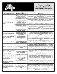
Trouble shooting guide<br />
The following information will guide you to repairs that may be made on site. For problems<br />
not covered here, contact your service center or our website for more extensive trouble<br />
shooting information in the service manual for your system.<br />
SYSTEM WILL NOT TURN ON, INDICATOR LIGHT DOES NOT LIGHT<br />
PROBABLE CAUSE<br />
CORRECTIVE ACTION<br />
COACH IGNITION NOT IN RUN<br />
POSITION<br />
TRANSMISSION NOT IN PARK OR<br />
NEUTRAL<br />
PARKING BRAKE NOT SET<br />
CONTROL HAS BEEN LEFT ON<br />
FOR MORE THAN FOUR<br />
MINUTES, AUTO SHUT OFF<br />
PROBABLE CAUSE<br />
TURN IGNITION TO RUN POSITION<br />
PLACE TRANSMISSION IN PARK OR<br />
NEUTRAL<br />
SET BRAKE<br />
PUSH ON/OFF BUTTON TWICE<br />
JACKS WILL NOT EXTEND, PUMP IS NOT RUNNING<br />
CORRECTIVE ACTION<br />
(OLD CONTROL) FUSE BLOWN<br />
REPLACE FUSE XF1 ON TOUCH PAD<br />
PROBABLE CAUSE<br />
JACKS WILL NOT EXTEND, PUMP IS RUNNING<br />
CORRECTIVE ACTION<br />
FLUID LEVEL LOW; PUMP<br />
CAVITATING<br />
PUMP HARNESS FUSE BLOWN<br />
ALL CONTROL FUSES BLOWN<br />
FILL TANK TO PROPER LEVEL WITH<br />
AUTOMATIC TRANSMISSION FLUID SEE TIP<br />
SHEET 140<br />
CHECK FOR +12 VDC AT THE RED WIRE FOR<br />
EACH SOLENOID VALVE. IF NONE, LOCATE<br />
FUSE ON HARNESS WITHIN 18" OF PUMP IN<br />
THE CORROGATED HARNESS. REPLACE<br />
FUSE WITH 10 AMP MINI FUSE<br />
CHECK FOR LOW VOLTAGE TO THE<br />
CONTROLLER, SHORTS IN THE WIRING.<br />
REPLACE FUSES
ONLY FRONT JACKS WILL NOT EXTEND, PUMP IS RUNNING<br />
PROBABLE CAUSE<br />
CORRECTIVE ACTION<br />
FUSE BLOWN<br />
CONTROL 500089, 500105, 500210: REPLACE<br />
FUSE XF5 ON TOUCH PAD : CONTROL<br />
500456, 500645, 500647 REPLACE “FRONT<br />
LEG “ FUSE<br />
ANY ONE OF THE REAR JACKS WILL NOT EXTEND, PUMP IS<br />
RUNNING<br />
PROBABLE CAUSE<br />
CORRECTIVE ACTION<br />
FUSE BLOWN<br />
CONTROL 500089, 500105, 500210: REPLACE<br />
FUSE XF3 ON TOUCH PAD FOR ROAD SIDE<br />
JACK REPLACE FUSE XF4 FOR CURB SIDE<br />
JACK<br />
CONTROL 500456, 500645, 500647: REPLACE<br />
'LEFT REAR JACK’ OR ‘RIGHT REAR JACK’<br />
FUSE ON CONTROL BOX<br />
ALL JACKS WILL NOT RETRACT OR WILL NOT RETRACT FULLY<br />
PROBABLE CAUSE<br />
CORRECTIVE ACTION<br />
DUMP VALVE FUSE BLOWN<br />
SYSTEM OVERFILLED WITH<br />
FLUID<br />
PUMP HARNESS FUSE BLOWN<br />
CONTROL 500089, 500105, 500210: REPLACE<br />
FUSE XF2 ON TOUCH PAD<br />
CONTROL 500456, 500645, 500647: REPLACE<br />
‘DUMP VALVE’ FUSE ON CONTROL BOX<br />
DRAIN FLUID TO RECOMMENDED LEVEL-<br />
SEE TIP 140<br />
LOCATE FUSE ON HARNESS WITHIN 18" OF<br />
PUMP IN THE CORROGATED HARNESS.<br />
REPLACE FUSE WITH 10 AMP MINI FUSE
ANY ONE OR TWO JACKS WILL NOT RETRACT AT ALL<br />
PROBABLE CAUSE<br />
CORRECTIVE ACTION<br />
BROKEN JACK SPRING (S) REPLACE JACK SPRING SEE TIP SHEET 34<br />
FUSE ON CONTROL PANEL<br />
BLOWN<br />
CONTROL 500089, 500105, 500210: REPLACE<br />
FUSE XF3 FOR ROAD SIDE JACK<br />
REPLACE FUSE XF4 FOR CURB SIDE JACK<br />
REPLACE FUSE XF5 FOR FRONT JACK (S)<br />
ON TOUCH PAD<br />
CONTROL 500456, 500645, 500647: REPLACE<br />
‘FRONT LEGS’, ‘LEFT REAR LEG’ OR ‘RIGHT<br />
REAR JACK’ FUSE ON CONTROL BOX<br />
JACK ROD GUIDE IS RUSTED OR<br />
DIRTY<br />
CLEAN CHROME ROD, GREASE ROD GUIDE<br />
IF EQUIPPED WITH GREASE FITTINGS.<br />
OTHERWISE LUBRICATE WITH SILICONE<br />
FLUID. IT MAY BE NECESSARY TO RESEAL<br />
JACK OR REPLACE.<br />
PROBABLE CAUSE<br />
ANY JACK RETRACTS VERY SLOWLY<br />
CORRECTIVE ACTION<br />
JACK ROD GUIDE IS RUSTED OR<br />
DIRTY<br />
CLEAN CHROME ROD, GREASE ROD GUIDE<br />
IF EQUIPPED WITH GREASE FITTINGS.<br />
OTHERWISE LUBRICATE WITH SILICONE<br />
FLUID. IT MAY BE NECESSARY TO RESEAL<br />
JACK OR REPLACE.
ANY JACK RETRACTS WITH NO POWER, WITH POSSIBLE<br />
POPPING SOUND<br />
PROBABLE CAUSE<br />
CORRECTIVE ACTION<br />
AIR IN SYSTEM<br />
CONTAMINATED FLUID<br />
JACK LEGS CREATE POPPING<br />
SOUND<br />
CHECK FOR COILS IN HOSE. REMOVE THE<br />
COIL IF PRESENT THEN EXTEND ALL JACKS<br />
TO FULL EXTENSION, THEN RETRACT<br />
FULLY, REPEAT 4 CYCLES WAITING A FEW<br />
MINUTES BETWEEN CYCLES, CHECK FLUID<br />
LEVEL IN BETWEEN CYCLES<br />
REPLACE FLUID, SEE PAGE A3, TIP SHEET<br />
140 AND 141.<br />
EXTEND JACK LEGS, CLEAN ROD,<br />
LUBRICATE WITH LIGHT WEIGHT GREASE IF<br />
EQUIPPED WITH GREASE FITTINGS OR<br />
LUBRICATE WITH SILICONE SPRAY<br />
DUE TO CHANGES IN TEMPERATURE,<br />
EXPANDING AND CONTRACTING OF FLUID<br />
WILL MAGNIFY THE PROBLEM OF POPPING<br />
JACKS, TO HELP MINIMIZE THIS REPLACE<br />
FLUID WITH MERCON V FLUID<br />
PROBABLE CAUSE<br />
PANEL JACKS DOWN LIGHT WILL NOT GO OFF<br />
WITH JACKS RETRACTED<br />
CORRECTIVE ACTION<br />
LOW FLUID LEVEL<br />
FILL TANK WITH AUTOMATIC TRANSMISSION<br />
FLUID SEE PAGE A3 AND TIP SHEET 140<br />
PANEL JACKS DOWN LIGHT AND ALARM WILL GO ON WHILE<br />
DRIVING, JACKS RETRACTED<br />
PROBABLE CAUSE<br />
CORRECTIVE ACTION<br />
LOW FLUID LEVEL<br />
FILL TANK WITH AUTOMATIC TRANSMISSION<br />
FLUID SEE TIP SHEET 140
POWER GEAR<br />
LIMITED WARRANTY<br />
<strong>Power</strong> <strong>Gear</strong> warrants to the original retail purchaser that the product will be free from defects in<br />
material and workmanship for a period of (2) years following the retail sales date. <strong>Power</strong> <strong>Gear</strong> will,<br />
at its option, repair or replace any part covered by this limited warranty which, following<br />
examination by <strong>Power</strong> <strong>Gear</strong> or its authorized distributors or dealers, is found to be defective under<br />
normal use and service. No claims under this warranty will be valid unless <strong>Power</strong> <strong>Gear</strong> or its<br />
authorized distributor or dealer is notified in writing of such claim prior to the expiration of the<br />
warranty period. Warranty is transferable pending documentation of original sale date of product.<br />
THIS WARRANTY SHALL NOT APPLY TO:<br />
• Failure due to normal wear and tear, accident, misuse, abuse, or negligence.<br />
• Products which are modified or altered in a manner not authorized by <strong>Power</strong> <strong>Gear</strong> in writing.<br />
• Failure due to misapplication of product.<br />
• Telephone or other communication expenses.<br />
• Living or travel expenses.<br />
• Overtime labor.<br />
• Failures created by improper installation of the product’s slideout system or slideout room to<br />
include final adjustments made at the plant for proper room extension/retraction; sealing interface<br />
between slideout rooms and side walls; synchronization of inner rails; or improper wiring or<br />
ground problems.<br />
• Failures created by improper installation of leveling systems, including final adjustments made at<br />
the plant, or low fluid level, wiring or ground problems.<br />
• Replacement of normal maintenance items.<br />
There is no other express warranty other than the foregoing warranty. THERE ARE NO IMPLIED<br />
WARRANTIES OF MERCHANTIBILITY OR FITNESS FOR A PARTICULAR PURPOSE. IN NO<br />
EVENT SHALL POWER GEAR BE LIABLE FOR ANY INCIDENTAL OR CONSEQUENTIAL<br />
DAMAGES. This warranty gives you specific legal rights, and you may also have other rights,<br />
which vary from state to state. Some states do not allow the limitations of implied warranties, or<br />
the exclusion of incidental or consequential damages, so the above limitations and exclusions may<br />
not apply to you.<br />
For service contact your nearest <strong>Power</strong> <strong>Gear</strong> authorized warranty service facility. Warranty<br />
service can be performed only by a <strong>Power</strong> <strong>Gear</strong> authorized service facility. This warranty<br />
will not apply to service at any other facility. At the time of requesting warranty service,<br />
evidence of original purchase date must be presented.<br />
<strong>Power</strong> <strong>Gear</strong><br />
1217 E. 7 th Street<br />
Mishawaka, IN 46544<br />
www.powergearus.com