Operation Manual for Automatic Leveling Systems - Power Gear
Operation Manual for Automatic Leveling Systems - Power Gear
Operation Manual for Automatic Leveling Systems - Power Gear

Create successful ePaper yourself
Turn your PDF publications into a flip-book with our unique Google optimized e-Paper software.
<strong>Operation</strong> <strong>Manual</strong><br />
<strong>for</strong> <strong>Automatic</strong><br />
<strong>Leveling</strong> <strong>Systems</strong><br />
© 01/09 <strong>Power</strong> <strong>Gear</strong> #82-L0379 Rev. 0C<br />
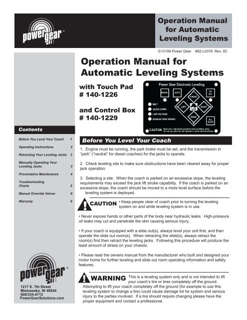
<strong>Operation</strong> <strong>Manual</strong> <strong>for</strong><br />
<strong>Automatic</strong> <strong>Leveling</strong> <strong>Systems</strong><br />
with Touch Pad<br />
# 140-1226<br />
and Control Box<br />
# 140-1229<br />
Contents<br />
Be<strong>for</strong>e You Level Your Coach 1<br />
Operating Instructions 2<br />
Retracting Your <strong>Leveling</strong> Jacks 3<br />
<strong>Manual</strong>ly Operating Your<br />
<strong>Leveling</strong> Jacks 3<br />
Preventative Maintenance 4<br />
Troubleshooting<br />
Charts 5<br />
<strong>Manual</strong> Override Valves 8<br />
Warranty 9<br />
Be<strong>for</strong>e You Level Your Coach<br />
1. Engine must be running, the park brake must be set, and the transmission in<br />
“park” (”neutral” <strong>for</strong> diesel coaches) <strong>for</strong> the jacks to operate.<br />
2. Check leveling site to make sure obstructions have been cleared away <strong>for</strong> proper<br />
jack operation.<br />
3. Selecting a site: When the coach is parked on an excessive slope, the leveling<br />
requirements may exceed the jack lift stroke capability. If the coach is parked on an<br />
excessive slope, the coach should be moved to a more level surface be<strong>for</strong>e the<br />
leveling system is deployed.<br />
!<br />
CAUTION<br />
• Keep people clear of coach prior to turning the leveling<br />
system on and while leveling system is in use.<br />
• Never expose hands or other parts of the body near hydraulic leaks. High-pressure<br />
oil leaks may cut and penetrate the skin causing serious injury.<br />
• If your coach is equipped with a slide out(s), always level your unit first, and then<br />
operate the slide out room(s). When retracting the slide(s), always retract the<br />
room(s) first then retract the leveling jacks. Following this procedure will produce the<br />
least amount of stress on your chassis.<br />
• Please read the owners manual from the manufacturer who built and designed your<br />
motor home <strong>for</strong> further leveling and slide out room operating in<strong>for</strong>mation and safety<br />
features.<br />
1217 E. 7th Street<br />
Mishawaka, IN 46544<br />
800/334-4712<br />
<strong>Power</strong><strong>Gear</strong>Solutions.com<br />
!<br />
WARNING<br />
This is a leveling system only and is not intended to lift<br />
your coach’s tire or tires completely off the ground.<br />
Attempting to lift your coach completely off the ground (<strong>for</strong> example to use this<br />
leveling system to change a tire) could cause damage tot he system and serious<br />
injury to the parties involved. If a tire should require changing please have the<br />
proper equipment and contact a professional.
Auto Level <strong>Operation</strong> <strong>Manual</strong> Page 2<br />
Operating Instructions<br />
<strong>Leveling</strong> Your Coach<br />
1. Turn on the ignition and start the coach. Your leveling control will start a self check sequence indicated by the<br />
lights on the panel blinking in a rotating pattern. It will turn off when it has finished its self check.<br />
2. Push the “On/Off” button on the control panel. The system is now operational and “On/Off” LED will turn on. (On<br />
some controls, there will be a 10 second wait period be<strong>for</strong>e operation is allowed. During this time, the wait light will<br />
flash.)<br />
Note: Check to see that the Low Voltage light is not illuminated. If so, start the engine and wait a few minutes to<br />
ensure that the battery voltage is good. The engine must be running <strong>for</strong> the jacks to operate.<br />
3. Check to see that the engage park brake light is not illuminated. If so, engage the parking brake. (Your coach will<br />
have to be in neutral or park to operate the system.)<br />
4. Push the “AUTO” button. The automatic leveling system will begin its leveling procedure. Please avoid movement<br />
in the coach during automatic leveling as it can cause errors in the results. It will signal that it has completed the<br />
process by illuminating the center green “<strong>Power</strong> <strong>Gear</strong> LEVEL” light. Check to make sure that all jacks are on the<br />
ground. Also check to make sure that no tire is off the ground. If so, your leveling process is complete. If further<br />
adjustments are needed, refer to the “<strong>Manual</strong> <strong>Operation</strong>” section.<br />
5. You can then turn the system off by pushing the On/Off button again.
Auto Level <strong>Operation</strong> <strong>Manual</strong> Page 3<br />
Retracting Your <strong>Leveling</strong> Jacks<br />
1. Turn on the ignition and start the coach.<br />
2. Turn on the system by pushing the “On/Off” button. The system is now operational and the “On/Off” LED will<br />
turn on.<br />
3. Push the “RETRACT-ALL JACKS” button. When the “JACKS DOWN” light turns off, visually check to make sure<br />
that all jacks have fully retracted. If so, your coach leveling system is ready to travel.<br />
!<br />
NOTE<br />
The right and left rear jacks<br />
are used to level the coach<br />
side to side. Pushing the<br />
“LEFT” button on the control<br />
panel will extend the left rear<br />
jack. Pushing the “RIGHT”<br />
button on the control will<br />
extend the right rear jack.<br />
<strong>Manual</strong>ly Operating Your <strong>Leveling</strong> Jacks<br />
<strong>Leveling</strong> Your Coach<br />
There are certain conditions where manually leveling your coach may be desirable.<br />
Conditions where large amounts of side to side leveling are necessary may work<br />
better using the manual leveling procedures that follow:<br />
1. Turn on the ignition and start the coach.<br />
2. Push the “On/Off” button to turn on the system.<br />
3. Push and hold the “MAN” button <strong>for</strong> 5-7 seconds in order <strong>for</strong> the system to<br />
switch to the manual mode. It will signal that it is in the manual mode when the<br />
light under the “MAN” button is illuminated.<br />
4. Push “FRONT” button until the front of the coach rises at least 3”. This is<br />
important and necessary to allow the coach to pivot when leveling side to side.<br />
If there is insufficient jack stroke to lift the front of the coach at least 3 inches,<br />
the coach will have to be moved to an area with less front to back slope, or a<br />
weight distribution block will have to be placed under the jack.<br />
5. Push the “REAR” button until jacks contact the ground.<br />
!<br />
NOTE<br />
If the “Wait” LED is ever<br />
flashing by itself, it means<br />
the control is busy and you<br />
cannot operate the jacks.<br />
After a short period of time<br />
(from 5 to 30 seconds), the<br />
“WAIT” LED will go off again,<br />
and you can resume<br />
operation as normal.<br />
6. Level the coach from front to rear by pushing the “REAR” button if the light<br />
under the “REAR” button is illuminated. If the light is illuminated above the<br />
“FRONT JACKS” button, push the “FRONT” button. In either case, keep button<br />
depressed until the green center “LEVEL ” light is illuminated, or both front and<br />
rear lights are dark.<br />
7. Level the coach from side to side by pushing the “RIGHT” button if the light<br />
beside the”RIGHT” button is illuminated. If the light beside the ”LEFT” button is<br />
illuminated, push the “LEFT” button until the “LEVEL” light is illuminated.<br />
8. Repeat steps 6 and 7 if needed.<br />
9. Turn power off to leveling system by pushing “ON/OFF” button.<br />
10. Visually inspect jack to ensure all pads are touching ground. Should one of<br />
the rear jacks not be touching the ground, press the corresponding left or right<br />
rear jack buttons to lower the appropriate jack to the ground. Never lift the<br />
wheels off the ground to level the coach. This can lead to an unsafe condition<br />
and damage to the leveling system or coach.
Auto Level <strong>Operation</strong> <strong>Manual</strong> Page 4<br />
Preventative Maintenance<br />
1. Check and/or fill the reservoir with the jacks and room(s) in the fully retracted<br />
position, each month. The fluid should be one inch onto the dipstick (on models<br />
so equipped) or to the bottom of the fill port on models without dipsticks.<br />
2. Change fluid every 24 months.<br />
3. Inspect and clean all hydraulic pump electrical connections every 12 months.<br />
4. Remove dirt and road debris from jacks as needed.<br />
5. If jacks are down <strong>for</strong> extended periods, it is recommended to spray exposed<br />
leveling jack chrome rods with a silicone lubricant every 5 to 7 days <strong>for</strong><br />
protection.<br />
6. If your coach is located in a salty environment (within 60 miles of coastal), it is<br />
recommended to spray the rods every 2 to 3 days with a silicone lubricant.<br />
7. Grease the fitting on the bottom of each jack cylinder with Lithium grease every<br />
20-30 uses.<br />
Recommended Hydraulic Fluids <strong>for</strong> Your Hydraulic Pump<br />
The fluids listed here are acceptable to use in your pump assembly. Contact coach<br />
manufacturer or selling dealer <strong>for</strong> in<strong>for</strong>mation about what specific fluid was installed<br />
in your system.<br />
• It is not recommended that hydraulic fluid and automatic transmission fluids be<br />
mixed in the reservoir.<br />
• In most applications, Type A automatic transmission fluid (ATF, Dexron III, etc.,)<br />
will work satisfactorily. Mercon V is also recommended as an alternative fluid <strong>for</strong><br />
<strong>Power</strong> <strong>Gear</strong> hydraulic systems.<br />
• If operating in cold temperatures (less than -10° F), the jacks may extend and<br />
retract slowly.<br />
• For cold weather operation, fluid specially-<strong>for</strong>mulated <strong>for</strong> low temperatures may<br />
be desirable. Mobil DTE 11M, Texaco Rando HDZ-15HVI, Kendall Hyden Glacial<br />
Blu, or any Mil. Spec. H5606 hydraulic fluids are recommended <strong>for</strong> cold weather<br />
operation.<br />
Please consult factory be<strong>for</strong>e using any other fluids than those specified<br />
here.
Auto Level <strong>Operation</strong> <strong>Manual</strong> Page 5<br />
Troubleshooting Tips<br />
T ro u b le S h o o tin g T ip s<br />
T h e fo llo w in g ch a rt co n ta in s tro u b le sh o o tin g tip s if yo u r syste m is n o t o p e ra tin g<br />
p ro p e rly, a n d th e to u ch p a d is not givin g yo u a tro u b le co d e<br />
Description<br />
T o u c h P a d w ill n o t<br />
tu rn O N<br />
Probable Cause<br />
C o a c h ig n itio n n o t in<br />
ru n p o s itio n .<br />
Corrective Action<br />
T u rn o n th e ig n itio n a n d s ta rt th e c o a c h . T h e e n g in e m u s t<br />
b e ru n n in g fo r th e ja c k s to o p e ra te .<br />
B lo w n fu s e o r<br />
trip p e d c irc u it<br />
b re a k e r<br />
R e p la c e fu s e o r re s e t b re a k e r<br />
J a c k s w ill n o t e x te n d .<br />
P u m p is not ru n n in g<br />
A u to S h u t O ff h a s<br />
oB clo cwu rre n fud s(b e /c o r 4<br />
trip p e d c irc u it<br />
b re a k e r<br />
P u s h O n /O ff b u tto n to tu rn th e c o n tro l b a c k O N .<br />
R e p la c e fu s e o r re s e t b re a k e r<br />
B a tte rie s a re w e a k .<br />
T u rn o n th e ig n itio n a n d s ta rt th e c o a c h . W a it a fe w m in u te s<br />
to a llo w th e b a tte rie s s o m e tim e to c h a rg e . T h e e n g in e m u s t<br />
b e ru n n in g fo r th e ja c k s to o p e ra te .<br />
J a c k s w ill n o t e x te n d<br />
(o r a re e x te n d in g<br />
s lo w ly), p u m p is<br />
ru n n in g<br />
F lu id le ve l lo w . F ill ta n k to p ro p e r le ve l w ith a u to m a tic tra n s m is s io n flu id ,<br />
s e e tip s h e e t 1 4 0 .<br />
J a c k s w ill n o t re tra c t<br />
fu lly<br />
B a tte rie s a re w e a k .<br />
A ir in th e s ys te m<br />
T u rn o n th e ig n itio n a n d s ta rt th e c o a c h . W a it a fe w m in u te s<br />
to a llo w th e b a tte rie s s o m e tim e to c h a rg e . T h e e n g in e m u s t<br />
b e ru n n in g fo r th e ja c k s to o p e ra te .<br />
C h e c k fo r c o ils in h o s e . R e m o ve th e c o il if p re s e n t th e n<br />
e x te n d a ll ja c k s to fu ll e x te n s io n , th e n re tra c t fu lly. R e p e a t 4<br />
c yc le s w a itin g a fe w m in u te s b e tw e e n c yc le s , c h e c k flu id<br />
le ve l in b e tw e e n c yc le s .
Auto Level <strong>Operation</strong> <strong>Manual</strong> Page 6<br />
Troubleshooting Tips, cont’d<br />
N o rm a l O p e ra tio n : D e scrip tio n o f F la shin g<br />
L ig h ts<br />
T h e fo llo w in g ch a rt co n ta in s in fo rm a tio n a b o u t d iffe re n t<br />
se ts o f fla sh in g ligh ts yo u w ill se e d u rin g n o rm a l o p e ra tio n<br />
Flashing<br />
Lights<br />
Mode<br />
Description of<br />
operation<br />
Wait W a it W ill n o t a llo w<br />
o p e ra tio n w h ile<br />
th e w a it lig h t is<br />
fla s h in g<br />
<strong>Power</strong><br />
<strong>Gear</strong><br />
Logo<br />
A n y tw o<br />
o f:<br />
Front,<br />
Right,<br />
Rear &<br />
Left<br />
Left,<br />
Right,<br />
Front,<br />
Rear &<br />
the <strong>Power</strong><br />
<strong>Gear</strong><br />
Logo<br />
A lre a d y<br />
L e ve l<br />
N o t L e ve l<br />
D ia g n o s tic<br />
C h e c k<br />
T h e <strong>Power</strong><br />
<strong>Gear</strong> Logo is<br />
fla s h in g<br />
in d e fin ite ly<br />
T h e s e tw o<br />
lig h ts c o u ld b e<br />
O N s o lid o r<br />
F la s h in g<br />
F o r<br />
a p p ro x im a te ly<br />
5 s e c o n d s , th e<br />
Front, Right,<br />
Rear & Left<br />
lig h ts fla s h in a<br />
c lo c k w is e<br />
p a tte rn , a lo n g<br />
w ith th e <strong>Power</strong><br />
<strong>Gear</strong> Logo<br />
Reason<br />
T h e s ys te m is b u s y. T h e w a it<br />
lig h t w ill g o o u t w ith in o n e<br />
m in u te . A t th a t tim e o p e ra tio n<br />
c a n b e re s u m e d .<br />
T h e c o a c h is a lre a d y le ve l a s it<br />
s its . H o w e ve r le ve lin g c a n s till<br />
b e e x e c u te d a s n o rm a l (to<br />
s ta b ilize th e c o a c h )<br />
T h is is n o rm a l a n ytim e th e<br />
c o a c h is n o t a lre a d y le ve l. T h e<br />
a rro w s in d ic a te th e s id e o f th e<br />
c o a c h th a t w o u ld n e e d to b e<br />
ra is e d to re a c h le ve l, if m a n u a l<br />
m o d e is u s e d .<br />
T h is is a n o rm a l d ia g n o s tic<br />
c h e c k a n ytim e th e ig n itio n is<br />
tu rn e d O N . T h e c o n tro l w ill<br />
e ith e r tu rn b a c k O F F a fte r th is<br />
d ia g n o s tic c h e c k , o r a tro u b le<br />
c o d e w ill s ta rt to fla s h .<br />
A ll lig h ts<br />
a re<br />
fla s h in g<br />
Emergency<br />
Retract<br />
A ll o f th e lig h ts<br />
a re fla s h in g ,<br />
and the jacks<br />
are retracting.<br />
A b u zze r<br />
s o u n d s fo r th e<br />
firs t 1 0<br />
s e c o n d s o f<br />
re tra c t<br />
W h ile th e ja c k s w e re e x te n d e d ,<br />
e ith e r th e p a rk in g b ra k e w a s<br />
re le a s e d o r th e tra n s m is s io n<br />
w a s p u t in to g e a r. T h is is<br />
n o rm a l b e h a vio r a s a s a fe ty<br />
fe a tu re . T h is is to p re ve n t<br />
d a m a g e to th e c o a c h o r<br />
le ve lin g s ys te m d u e to d rivin g<br />
a w a y w ith yo u r ja c k s d o w n .<br />
A ll lig h ts<br />
a re<br />
fla s h in g<br />
P ro g ra m<br />
M o d e<br />
A ll o f th e lig h ts<br />
a re fla s h in g<br />
in d e fin ite ly. N o<br />
b u zze r is<br />
s o u n d in g .<br />
T h is m o d e w a s in te n tio n a lly<br />
e n te re d , a n d c a n n o t b e e n te re d<br />
b y a c c id e n t. S e e T IP S h e e t #<br />
1 5 3 fo r a d e s c rip tio n o f<br />
o p e ra tio n in p ro g ra m m o d e .
Auto Level <strong>Operation</strong> <strong>Manual</strong> Page 7<br />
T ro u b le C o d e s: D e scrip tio n o f F la shin g L ig h ts<br />
T h e fo llo w in g ch a rt co n ta in s tro u b le sh o o tin g tip s if yo u r syste m is n o t o p e ra tin g p ro p e rly,<br />
b u t th e to u ch p a d is givin g yo u a tro u b le co d e<br />
Flashing<br />
Lights<br />
Low<br />
Voltage<br />
On/Off and<br />
Wait<br />
Fault<br />
Code<br />
L o w<br />
V o lta g e<br />
T ra n s m is s<br />
io n<br />
Park Brake P a rk<br />
B ra k e<br />
Left, Right, E x c e s s ive<br />
Front, Rear S lo p e<br />
& the<br />
<strong>Power</strong><br />
<strong>Gear</strong> Logo<br />
Jacks<br />
Down &<br />
Wait<br />
On/Off ,<br />
Jacks<br />
Down &<br />
Park Brake<br />
All of the<br />
Lights are<br />
on Solid,<br />
indefinitely<br />
Left, Right<br />
& the<br />
<strong>Power</strong><br />
<strong>Gear</strong> Logo<br />
P re s s u re<br />
L o s s<br />
C o m m u n i<br />
c a tio n<br />
E rro r<br />
In te rn a l<br />
E rro r<br />
T im e o u t<br />
E rro r<br />
Description of operation<br />
L o w V o lta g e lig h t is O N<br />
s o lid o r fla s h in g . M a y o r<br />
m a y n o t a llo w o p e ra tio n<br />
W ill n o t a llo w o p e ra tio n<br />
W ill n o t a llo w o p e ra tio n<br />
T h e lig h ts a re fla s h in g<br />
in d e fin ite ly, b u t le ve lin g is<br />
p o s s ib le<br />
W ill n o t a llo w o p e ra tio n<br />
Probable Cause Corrective Action<br />
B a tte rie s a re<br />
w e a k .<br />
T ra n s m is s io n is<br />
in g e a r<br />
P a rk in g B ra k e is<br />
n o t e n g a g e d<br />
1 ) T o o<br />
s te e p /u n e ve n<br />
te rra in<br />
2 ) T h e c o n tro l<br />
w a s im p ro p e rly<br />
p ro g ra m m e d<br />
T h e le ve lin g<br />
s ys te m h a s a<br />
p re s s u re le a k a n d<br />
n e e d s s e rvic e<br />
W ill n o t a llo w o p e ra tio n F a u lty w irin g ,<br />
p o o r c o n n e c tio n s ,<br />
o r fa u lty<br />
c o m p o n e n t<br />
W ill n o t a llo w o p e ra tio n<br />
L e ve lin g o p e ra tio n w a s<br />
a b o rte d . T h e re a re s e ve ra l<br />
in te rn a l tim e rs th a t c o u ld<br />
h a ve trip p e d . T h e s e tim e rs<br />
a re b u ilt-in to p ro te c t th e<br />
h yd ra u lic p u m p o r th e<br />
c o a c h fro m b e in g d a m a g e d .<br />
T h is is a n in te rn a l<br />
e rro r<br />
B a tte rie s a re<br />
w e a k .<br />
T u rn o n th e ig n itio n a n d s ta rt th e<br />
c o a c h . W a it a fe w m in u te s to a llo w<br />
th e b a tte rie s s o m e tim e to c h a rg e .<br />
T h e e n g in e m u s t b e ru n n in g fo r th e<br />
ja c k s to o p e ra te .<br />
P la c e th e tra n s m is s io n in P a rk (o r<br />
N e u tra l fo r d ie s e l c o a c h e s ).<br />
E n g a g e th e p a rk in g b ra k e<br />
1 ) M o ve c o a c h to g ro u n d th a t is<br />
m o re le ve l<br />
2 ) S e e T IP S h e e t # 1 5 3 to<br />
re p ro g ra m c o n tro l<br />
T a k e yo u r c o a c h to a n a u th o rize d<br />
s e rvic e c e n te r fo r re p a ir.<br />
N o te : T h e e le c tro n ic s a re fin e a n d<br />
d o n o t n e e d s e rvic e . O n ly th e<br />
h yd ra u lic p o rtio n o f th e s ys te m<br />
n e e d s s e rvic e .<br />
C h e c k to m a k e s u re th a t a ll<br />
c o n n e c tio n s a re tig h t a n d p ro p e rly<br />
c o n n e c te d . C yc le th e ig n itio n p o w e r<br />
to re s e t. If th a t d o e s n o t w o rk , try<br />
re p la c in g c o m p o n e n ts in d ivid u a lly,<br />
in th e fo llo w in g o rd e r:<br />
a ) H a rn e s s (b e tw e e n th e to u c h<br />
p a d a n d c o n tro l)<br />
b ) th e to u c h p a d<br />
c ) th e c o n tro l<br />
A n e w c o n tro l b o x is n e e d e d .<br />
H o w e ve r, a to u c h p a d is not<br />
n e e d e d .<br />
T u rn o n th e ig n itio n a n d s ta rt th e<br />
c o a c h . W a it a fe w m in u te s to a llo w<br />
th e b a tte rie s s o m e tim e to c h a rg e .<br />
T h e e n g in e m u s t b e ru n n in g fo r th e<br />
ja c k s to o p e ra te .<br />
T h e m o s t c o m m o n a re<br />
a ) J a c k s to o k to o lo n g to<br />
re tra c t o r<br />
b ) J a c k s to o k to o lo n g to<br />
fin is h a u to le ve lin g<br />
T o o s te e p /u n e ve n<br />
te rra in<br />
T h ic k h yd ra u lic<br />
flu id c a u s e d b y<br />
c o ld w e a th e r<br />
A ir in th e L e ve lin g<br />
S ys te m<br />
M o ve th e c o a c h to g ro u n d th a t is<br />
m o re le ve l<br />
S e e P a g e 4 fo r re c o m m e n d e d c o ld<br />
w e a th e r h yd ra u lic flu id<br />
C h e c k fo r c o ils in h o s e . R e m o ve th e<br />
c o il if p re s e n t th e n e x te n d a ll ja c k s
Auto Level <strong>Operation</strong> <strong>Manual</strong> Page 8<br />
<strong>Manual</strong> Override Valves<br />
In case of a loss of power at the pump assembly, the manual override valves (MOV’s) can be used to retract the leveling<br />
jacks. Not all <strong>Power</strong> <strong>Gear</strong> leveling system pumps have manual override valves. <strong>Power</strong> units <strong>for</strong> double acting systems<br />
that have manual override valves have flexible rubber caps on the valves and a hex override nut under the button cap on<br />
the electric motor.<br />
To use the MOV’s:<br />
1. Remove the button cap from the end of the electric motor. First remove the two Phillips head screws from the top of<br />
the motor. The button cap can now be removed from the electric motor. You should now see a 7/16” override nut on the<br />
end of the electric motor shaft.<br />
2. After verifying all personnel and tools are clear of the press the rubber cap on the valve<br />
<strong>for</strong> the front legs valve. The front end of the coach will start to descend. Only allow the<br />
coach to descend <strong>for</strong> 2 inches.<br />
3. Push and hold the rubber cap on the Roadside Rear valve. Allow the coach to descend<br />
<strong>for</strong> 2 inches.<br />
4. Push and hold the rubber cap on the Curbside Rear valve. Allow the coach to descend<br />
<strong>for</strong> 2 inches.<br />
5. Repeat procedures 2-4 until the weight of the coach is transferred off the jacks and onto<br />
the suspension and tires.<br />
!<br />
WARNING<br />
Care must be taken<br />
during the manual<br />
retraction of jacks to<br />
prevent bodily injury or<br />
death. The next step<br />
will allow fluid to<br />
transfer from the legs<br />
to the reservoir. This<br />
procedure will allow the<br />
coach to descend.<br />
Keep all personnel and<br />
equipment clear of the<br />
coach. Make sure no<br />
one is under the coach<br />
prior to this procedure.<br />
Do not have any body<br />
parts or equipment<br />
positioned such that<br />
the coach will descend<br />
on it.<br />
6. This procedure will retract the front legs. Using a 7/16” socket attached to a drill, spin the override nut clockwise<br />
while holding the button on the front legs valve. Stop when the legs are fully retracted.<br />
7. This procedure will retract the roadside rear leg. After the front legs are retracted, press the button on the roadside<br />
rear leg valve and spin the override nut clockwise. Stop when the leg is fully retracted.<br />
8. This procedure will retract the curbside rear leg. After the front legs are retracted, press the button on the curbside<br />
rear leg valve and spin the override nut clockwise. Stop when the leg is fully retracted.<br />
9. Replace the button cap on the electric motor and securely tighten the Phillips head screws.
Auto Level <strong>Operation</strong> <strong>Manual</strong> Page 9<br />
<strong>Power</strong> <strong>Gear</strong> Limited Warranty<br />
<strong>Power</strong> <strong>Gear</strong> warrants to the original retail purchaser that the product will be free<br />
from defects in material and workmanship <strong>for</strong> a period of two (2) years. Labor to<br />
repair these components will be covered <strong>for</strong> two (2) years. <strong>Power</strong> <strong>Gear</strong> will, at its<br />
option, repair or replace any part covered by this limited warranty which, following<br />
examination by <strong>Power</strong> <strong>Gear</strong> or its authorized distributors or dealers, is found to be<br />
defective under normal use and service. No claims under this warranty will be<br />
valid unless <strong>Power</strong> <strong>Gear</strong> or its authorized distributor or dealer is notified in writing<br />
of such claim prior to the expiration of the warranty period. Warranty is<br />
transferable pending documentation of original sale date of product.<br />
THIS WARRANTY SHALL NOT APPLY TO:<br />
• Failure due to normal wear and tear, accident, misuse, abuse, or negligence.<br />
• Products which are modified or altered in a manner not authorized by <strong>Power</strong><br />
<strong>Gear</strong> in writing.<br />
• Failure due to misapplication of product.<br />
• Telephone or other communication expenses.<br />
• Living or travel expenses.<br />
• Overtime labor.<br />
• Failures created by improper installation of slideout systems to include final<br />
adjustments made at the plant; sealing interface between slideout rooms and<br />
side walls; synchronization of rails; or improper wiring or ground problems.<br />
• Failures created by improper installation of leveling systems, including final<br />
adjustments made at the plant, or low fluid level, wiring or ground problems.<br />
• Replacement of normal maintenance items.<br />
There is no other express warranty other than the <strong>for</strong>egoing warranty. THERE<br />
ARE NO IMPLIED WARRANTIES OF MERCHANTABILITY OR FITNESS FOR A<br />
PARTICULAR PURPOSE. IN NO EVENT SHALL POWER GEAR BE LIABLE<br />
FOR ANY INCIDENTAL OR CONSEQUENTIAL DAMAGES. This warranty gives<br />
you specific legal rights, and you may also have other rights, which vary from<br />
state to state. Some states do not allow the limitations of implied warranties, or<br />
the exclusion of incidental or consequential damages, so the above limitations<br />
and exclusions may not apply to you.<br />
For service contact your nearest <strong>Power</strong> <strong>Gear</strong> authorized warranty service facility<br />
or call 1-800-334-4712. Warranty service can be per<strong>for</strong>med only by a <strong>Power</strong> <strong>Gear</strong><br />
authorized service facility. This warranty will not apply to service at any other<br />
facility. At the time of requesting warranty service, evidence of original purchase<br />
date must be presented.<br />
1217 E. 7th Street<br />
Mishawaka, IN 46544<br />
800/334-4712