
You also want an ePaper? Increase the reach of your titles
YUMPU automatically turns print PDFs into web optimized ePapers that Google loves.
TIP<br />
SHEET<br />
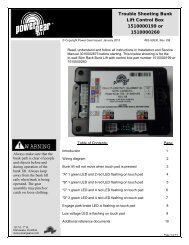
Upgrade Procedure<br />
for Room Locks<br />
907100111& 907100112<br />
Content<br />
<strong>WARNING</strong><br />
Room lock must be<br />
retracted before<br />
starting this operation.<br />
NOTE<br />
If you have Room Lock<br />
LH Assembly<br />
907100111, order kit<br />
#1010002312. This kit<br />
correctly has a “Right”<br />
motor.<br />
If you have Room Lock<br />
RH Assembly<br />
907100112, order kit<br />
#1010002315. This kit<br />
correctly has a “Left”<br />
motor.<br />
If you do not know<br />
which room lock is<br />
installed on the coach,<br />
contact the coach<br />
builder to determine the<br />
correct part before<br />
ordering parts.<br />
You can also refer to<br />
step #10 in this<br />
document to see what<br />
motor is used to<br />
determine which kit is<br />
needed.<br />
Warranty Time<br />
Diagnostic and Repair = .5 Hour Total<br />
1217 E. 7 th St.<br />
Mishawaka, IN 46544<br />
www.powergearus.com<br />
© Copyright <strong>Power</strong> <strong>Gear</strong> Issued: January 2012 #82-S0519, Rev. 0F 6/12<br />
This supersedes all previous revisions of this document.<br />
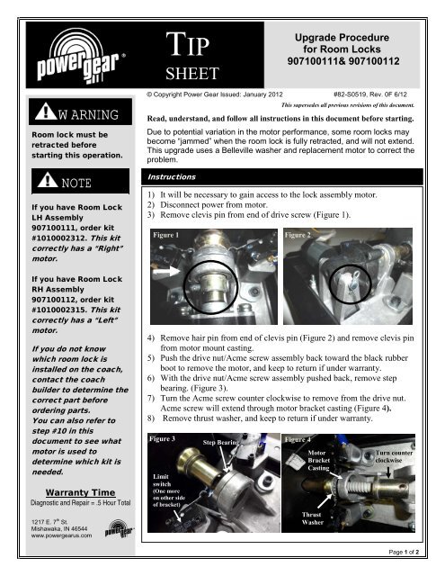
Read, understand, and follow all instructions in this document before starting.<br />
Due to potential variation in the motor performance, some room locks may<br />
become “jammed” when the room lock is fully retracted, and will not extend.<br />
This upgrade uses a Belleville washer and replacement motor to correct the<br />
problem.<br />
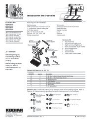
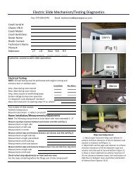
Instructions<br />
1) It will be necessary to gain access to the lock assembly motor.<br />
2) Disconnect power from motor.<br />
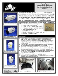
3) Remove clevis pin from end of drive screw (Figure 1).<br />
Figure 1 Figure 2<br />
4) Remove hair pin from end of clevis pin (Figure 2) and remove clevis pin<br />
from motor mount casting.<br />
5) Push the drive nut/Acme screw assembly back toward the black rubber<br />
boot to remove the motor, and keep to return if under warranty.<br />
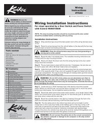
6) With the drive nut/Acme screw assembly pushed back, remove step<br />
bearing. (Figure 3).<br />
7) Turn the Acme screw counter clockwise to remove from the drive nut.<br />
Acme screw will extend through motor bracket casting (Figure 4).<br />
8) Remove thrust washer, and keep to return if under warranty.<br />
Figure 3<br />
Step Bearing<br />
Figure 4<br />
Motor<br />
Bracket<br />
Casting<br />
Limit<br />
switch<br />
(One more<br />
on other side<br />
of bracket)<br />
Thrust<br />
Washer<br />
Turn counter<br />
clockwise<br />
Page 1 of 2
82-S0519 Upgrade Procedure for Room Lock 907100111 & 907100112<br />
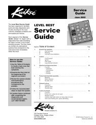
CAUTION<br />
9) Lubricate both sides of Belleville washer (Part #2010000474) with Sta-<br />
Lube Multipurpose Super White Grease SL3151 (or equivalent), and<br />
install with curve toward flange of the acme screw (Figure 5, 6, and 7).<br />
Figure 5 Figure 6<br />
Motor #1820130<br />
Figure 7<br />
L<br />
Motor<br />
Output<br />
Shaft<br />
Correct position<br />
of Bellville washer<br />
(Curvature enhanced<br />
for illustration)<br />
Acme<br />
Screw<br />
Flange<br />
Motor #1820131<br />
R<br />
10) Reverse steps 2 thru 7 to re-assemble the room lock. You may have to<br />
turn the Acme screw or motor shaft to align the holes. Make sure to<br />
use the new replacement motor during assembly.<br />
For Left Hand Room Lock #907100111, use motor #1820131 (It will<br />
have “R” stamped into metal housing. See picture to the left).<br />
NOTE: The motor “hand” position is opposite the assembly “hand”<br />
position.<br />
For Right Hand Room Lock #907100112, use motor #1820130 (It will<br />
have “L” stamped into metal housing. See picture to the left).<br />
NOTE: The motor “hand” position is opposite the assembly “hand”<br />
position.<br />
11) Verify operation of assembly by extending & retracting lock assembly<br />
several times.<br />
12) Test slide out room to make sure it moves out and in. If the room does<br />
not operate, check and adjust the two limit switches on the room lock.<br />
13) Re-install access panels as required.<br />
1217 E. 7 th St.<br />
Mishawaka, IN 46544<br />
www.powergearus.com<br />
Page 2 of 2