PowerWorld Transmission Line Parameter Calculator Version 2
PowerWorld Transmission Line Parameter Calculator Version 2
PowerWorld Transmission Line Parameter Calculator Version 2

Create successful ePaper yourself
Turn your PDF publications into a flip-book with our unique Google optimized e-Paper software.
<strong>PowerWorld</strong> <strong>Transmission</strong> <strong>Line</strong><br />
<strong>Parameter</strong> <strong>Calculator</strong> <strong>Version</strong> 2<br />
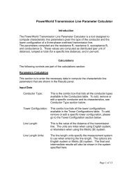
Introduction<br />
The <strong>PowerWorld</strong> <strong>Transmission</strong> <strong>Line</strong> <strong>Parameter</strong> <strong>Calculator</strong> (Trans<strong>Line</strong>Calc) is a tool<br />
designed to compute characteristic line parameters given the type of the conductor and<br />
the tower configuration of a three-phase overhead transmission line.<br />
The parameters computed are the resistance R, reactance X, susceptance B, and<br />
conductance G. These values are computed as distributed (per unit of distance),<br />
lumped or total (for a specific line distance), and in per-unit.<br />
<strong>PowerWorld</strong> provides Trans<strong>Line</strong>Calc as a stand-alone program (.exe file) and also as<br />
an automation server that can run from <strong>PowerWorld</strong> Simulator directly or from an<br />
external application (.dll file).<br />
2001 South First Street<br />
Champaign, IL 61820, USA<br />
(217) 384-6330<br />
www.powerworld.com<br />
support@powerworld.com
<strong>Transmission</strong> <strong>Line</strong> <strong>Parameter</strong> <strong>Calculator</strong> <strong>Version</strong> 2<br />
Table of Contents<br />
1 FEATURES ........................................................................................................................................................ 1<br />
1.1 CALCULATIONS ........................................................................................................................................... 1<br />
1.1.1 <strong>Parameter</strong>s Calculation ......................................................................................................................... 1<br />
1.1.2 Ampere to MVA Limit Conversion ......................................................................................................... 3<br />
1.1.3 Reverse Lookup ...................................................................................................................................... 3<br />
1.2 CONDUCTOR TYPE ...................................................................................................................................... 5<br />
1.2.1 Edit By Form.......................................................................................................................................... 5<br />
1.2.2 Edit By Table ......................................................................................................................................... 5<br />
1.3 TOWER CONFIGURATION ............................................................................................................................. 7<br />
1.3.1 Edit By Form.......................................................................................................................................... 7<br />
1.3.2 Edit By Table ......................................................................................................................................... 7<br />
1.4 DATABASE CONTROLS ................................................................................................................................ 9<br />
2 AUTOMATION SERVER .............................................................................................................................. 10<br />
2.1 COM OBJECT INITIALIZATION AND DESTRUCTION ................................................................................... 10<br />
2.2 METHODS OF THE SIMAUTO OBJECT ......................................................................................................... 11<br />
2.2.1 Set<strong>Parameter</strong>s ...................................................................................................................................... 11<br />
2.2.2 Get<strong>Parameter</strong>sPU ................................................................................................................................ 11<br />
2.2.3 Get<strong>Parameter</strong>sLumped ........................................................................................................................ 12<br />
3 CALCULATIONS ........................................................................................................................................... 13<br />
3.1 DISTRIBUTED PARAMETERS ...................................................................................................................... 13<br />
3.2 LUMPED (TOTAL) PARAMETERS ................................................................................................................ 15<br />
3.3 BASE VALUES ........................................................................................................................................... 16<br />
3.4 PER UNIT (PU) PARAMETERS .................................................................................................................... 17<br />
3.5 MVA TO AMPERE AND AMPERE TO MVA LIMITS CONVERSION .............................................................. 17<br />
4 REFERENCES ................................................................................................................................................. 17<br />
©<strong>PowerWorld</strong> Corporation<br />
ii<br />
April 22, 2013
<strong>Transmission</strong> <strong>Line</strong> <strong>Parameter</strong> <strong>Calculator</strong> <strong>Version</strong> 2<br />
1 Features<br />
1.1 Calculations<br />
The following controls are part of the calculations section:<br />
1.1.1 <strong>Parameter</strong>s Calculation<br />
This section is to enter the necessary data to compute the characteristic line parameters<br />
that are shown in the Results panel.<br />
Input Data<br />
Conductor Type:<br />
Tower Configuration:<br />
<strong>Line</strong> Length:<br />
<strong>Line</strong> Length Units:<br />
Power Base:<br />
Voltage Base:<br />
Impedance Base:<br />
Admittance Base:<br />
This is the combo box that lists all the conductor types<br />
available in the Conductors table. To add, remove or edit a<br />
specific conductor and its characteristics, see Conductor<br />
Type section below.<br />
This combo box lists all the tower configurations available in<br />
the Tower Configurations table. To add, remove or edit a<br />
specific tower configuration, please go to the Tower<br />
Configuration section below.<br />
This is the value of the distance of the transmission line.<br />
The units are miles when using English system, or<br />
kilometers when using the Metric (SI) system.<br />
The line length units specify the measurement system to use<br />
when entering the line length. The options are English<br />
system or Metric (SI) system. The final and intermediate<br />
results will also be shown in the system specified here.<br />
The system voltampere base in MVA.<br />
The line-line voltage base in KV.<br />
The impedance base in Ohms. This value is automatically<br />
computed when the power base and the voltage base are<br />
entered or modified.<br />
The admittance base in Siemens. It is also automatically<br />
computed as the inverse of the impedance base.<br />
©<strong>PowerWorld</strong> Corporation<br />
1<br />
April 22, 2013
<strong>Transmission</strong> <strong>Line</strong> <strong>Parameter</strong> <strong>Calculator</strong> <strong>Version</strong> 2<br />
Lumped Results<br />
When all the input data is entered, the results automatically will be displayed. The<br />
values for R, X, B and G are shown in two different sections, one for actual total values<br />
per phase, and one for Per Unit values. The Power Surge Impedance Loading is also<br />
calculated.<br />
Distributed Results<br />
The values in this section will be displayed automatically too when all the input data is<br />
entered. The values for R, X, B and G are shown in actual values per distance units per<br />
phase.<br />
Intermediate Results<br />
The intermediate values calculated to compute the R, X, B, and G values are displayed<br />
here. The computed geometric mean radius and geometric mean distance are shown<br />
in the Distributed values section. The characteristic impedance and propagation factor<br />
are displayed in the Lumped values section.<br />
Note: To see the specific calculations used in this program, see the Calculations<br />
section, at the end of this document.<br />
Figure 1: Calculations Tab<br />
©<strong>PowerWorld</strong> Corporation<br />
2<br />
April 22, 2013
<strong>Transmission</strong> <strong>Line</strong> <strong>Parameter</strong> <strong>Calculator</strong> <strong>Version</strong> 2<br />
1.1.2 Ampere to MVA Limit Conversion<br />
This section converts the limits of the transmission line from Amperes to MVAs, given<br />
the voltage base, and vice versa.<br />
1.1.3 Reverse Lookup<br />
Figure 2: Amp to MVA Conversion<br />
Use this section to do a reverse lookup of the conductor, given a tower configuration<br />
and the characteristic line parameters in per unit.<br />
Input Data<br />
Tower Configuration:<br />
<strong>Line</strong> Length:<br />
<strong>Line</strong> Length Units:<br />
This combo box lists all the tower configurations available in<br />
the Tower Configurations table. To add, remove or edit a<br />
specific tower configuration, please go to the Tower<br />
Configuration section below.<br />
This is the value of the distance of the transmission line.<br />
The units are miles when using English system, or<br />
kilometers when using the Metric (SI) system.<br />
The line length units specify the measurement system to use<br />
when entering the line length. The options are English<br />
©<strong>PowerWorld</strong> Corporation<br />
3<br />
April 22, 2013
<strong>Transmission</strong> <strong>Line</strong> <strong>Parameter</strong> <strong>Calculator</strong> <strong>Version</strong> 2<br />
system or Metric (SI) system. The final and intermediate<br />
results will also be shown in the system specified here.<br />
Power Base:<br />
Voltage Base:<br />
The system voltampere base in MVA.<br />
The line-line voltage base in KV.<br />
R: Resistance in per unit per phase.<br />
X: Reactance in per unit per phase.<br />
B: Susceptance in per unit per phase.<br />
G: Conductance in per unit per phase.<br />
Results<br />
When all the input data is entered, click on the Calculate button to display the results in<br />
the table on the right. This table will compute the characteristic line parameters for each<br />
of the conductors in the data base, using the input tower configuration. The conductors<br />
will be sorted according to the match of their characteristics line parameters results with<br />
the input characteristic line parameters.<br />
©<strong>PowerWorld</strong> Corporation<br />
4<br />
April 22, 2013
<strong>Transmission</strong> <strong>Line</strong> <strong>Parameter</strong> <strong>Calculator</strong> <strong>Version</strong> 2<br />
1.2 Conductor Type<br />
This section is used to add, remove, rename, and edit the information related to the<br />
conductor types. This can be done in two ways: using the form for an individual<br />
conductor type, or using the table for all the conductor types available.<br />
1.2.1 Edit By Form<br />
Conductors are identified by a unique code word. All the available conductors are listed<br />
in the Conductor Code Word combo box. By selecting one conductor, all its properties<br />
are displayed in the form. There, the user is able to modify any of those values. After<br />
modification of any value, the user has to save the changes by clicking on the button<br />
Save before changing tabs, otherwise the changes will be lost.<br />
By clicking on New, a message prompting for a name for a new conductor will be<br />
shown. By clicking on Rename, a new name for the current conductor type is required.<br />
In order to save the current conductor type with a different name is necessary to click on<br />
Save As. Finally, to remove the current conductor the user can do so by clicking on the<br />
Delete button.<br />
1.2.2 Edit By Table<br />
In this tab, all the conductor types are shown as records in a table, where every field is<br />
a characteristic of the conductor. In order to edit the records in this table, use the<br />
Database button described in the Database section. While editing the table, the user<br />
can not change of tab until changes are posted or discarded.<br />
Conductor Properties<br />
The available properties of the conductors are the following:<br />
Code Word:<br />
Area:<br />
Aluminum strands:<br />
Steel layers:<br />
Aluminum layers:<br />
External diameter:<br />
Code name for the type of conductor. The names of bird<br />
species are typically used. Code Word has to be unique.<br />
The area of aluminum conductor in circular mils. A circular<br />
mil is the cross-sectional area of a circular conductor having<br />
a diameter of 1 mil. One mil is one thousandth of an inch<br />
(0.001”).<br />
Number of aluminum strands.<br />
Number of steel strands.<br />
Number of aluminum layers.<br />
Outside diameter of the conductor in inches.<br />
©<strong>PowerWorld</strong> Corporation<br />
5<br />
April 22, 2013
<strong>Transmission</strong> <strong>Line</strong> <strong>Parameter</strong> <strong>Calculator</strong> <strong>Version</strong> 2<br />
GMR:<br />
DC Resistance:<br />
AC Resistance 25:<br />
AC Resistance 50:<br />
AC Resistance 75:<br />
Inductive Reactance:<br />
Geometric Mean Radius in feet.<br />
DC resistance of the conductor at 20°C per 1 mile in Ohms.<br />
AC resistance of the conductor at 60 Hz and 25°C per 1 mile<br />
in Ohms.<br />
AC resistance of the conductor at 60 Hz and 50°C per 1 mile<br />
in Ohms.<br />
AC resistance of the conductor at 60 Hz and 75°C per 1 mile<br />
in Ohms.<br />
Inductive reactance per conductor at 1 foot spacing at 60 Hz<br />
in Ohms/mile.<br />
Capacitive Reactance: Capacitive reactance per conductor at 1 foot spacing at 60<br />
Hz in MegaOhms/mile.<br />
Figure 3: Conductors Tab (Editing by Table)<br />
©<strong>PowerWorld</strong> Corporation<br />
6<br />
April 22, 2013
<strong>Transmission</strong> <strong>Line</strong> <strong>Parameter</strong> <strong>Calculator</strong> <strong>Version</strong> 2<br />
1.3 Tower Configuration<br />
This part is used to add, remove, rename, and edit the information related to the tower<br />
configurations. This can be done in two ways: using the form for an individual tower<br />
configuration, or using the table for all the tower configurations available.<br />
1.3.1 Edit By Form<br />
Tower configurations are identified by a unique name. All the available tower<br />
configurations are listed in the Tower Configuration Name combo box. By selecting one<br />
specific tower configuration, all its characteristics are displayed in the form. There, the<br />
user can modify any of those characteristics. After modification of any value, the user<br />
has to save the changes by clicking on the button Save before changing tabs, otherwise<br />
the changes will be lost.<br />
By clicking on New, a message prompting for a name for a new tower configuration will<br />
be shown. By clicking on Rename, a new name for the current tower configuration is<br />
required. In order to save the current tower configuration with a different name is<br />
necessary to click on Save As. Finally, to remove the current tower configuration the<br />
user can do so by clicking on the Delete button.<br />
1.3.2 Edit By Table<br />
In this tab, all the tower configurations are shown as records in a table, where every<br />
field is a value of the tower configuration. In order to edit the records in this table, use<br />
the Database button described in the Database section. While editing the table, the<br />
user can not change of tab until changes are posted or discarded.<br />
Tower Configuration Values<br />
The values of the tower configuration are the following:<br />
Name:<br />
Phase spacing:<br />
Name for the tower configuration. Name has to be unique.<br />
x and y coordinates of phases A, B and C positions. Values<br />
are in feet for English system and meters for Metric (SI)<br />
system. When these values are modified, the phase spacing<br />
graph is automatically updated. Draw axis has to be<br />
checked for x and y axis to be drawn in the graph.<br />
Conductors per bundle: This section specifies the number of conductors (either<br />
single conductor or a bundle of conductors) per phase. The<br />
maximum number of conductors per bundle allowed is 4.<br />
©<strong>PowerWorld</strong> Corporation<br />
7<br />
April 22, 2013
<strong>Transmission</strong> <strong>Line</strong> <strong>Parameter</strong> <strong>Calculator</strong> <strong>Version</strong> 2<br />
Use regular spacing:<br />
Conductors spacing:<br />
Temperature:<br />
Frequency:<br />
System of units:<br />
When using a bundle of conductors, checking the Use<br />
Regular Spacing of check box will use the specified value<br />
as a regular spacing among the conductors. If the Use<br />
Regular Spacing of check box is not checked, then the<br />
custom conductors spacing section has to be used.<br />
x and y coordinates of the conductors in the bundle. Values<br />
are in feet for English system and meters for Metric (SI)<br />
system. When these values are modified, the bundle<br />
spacing graph is automatically updated. Draw axis has to<br />
be checked for x and y axis to be drawn in the graph.<br />
The temperature is in Celsius degrees regardless of the<br />
System of units that is selected.<br />
Frequency of the system in Hertz.<br />
The system of units used to specify the values of the tower<br />
configuration. The options are English system or Metric (SI)<br />
system. The units specified here not necessarily have to<br />
math the units specified in the Input Data section.<br />
Figure 4: Tower Configuration (Editing by Form)<br />
©<strong>PowerWorld</strong> Corporation<br />
8<br />
April 22, 2013
<strong>Transmission</strong> <strong>Line</strong> <strong>Parameter</strong> <strong>Calculator</strong> <strong>Version</strong> 2<br />
1.4 Database Controls<br />
The conductor type and tower configurations tables are read by default from the file<br />
conductors.mbd, which is a MS Access® database. This database can be read from<br />
another *.mdb file by clicking on the Select Conductors and Configurations<br />
Database button.<br />
Note: The conductors.mdb file can also be viewed and edited in MS Access®.<br />
In order to edit a record in the database tables, the user can use the toolbar designed to<br />
do that. Following there is a figure showing this toolbar:<br />
The First, Prior, Next, and Last buttons are used to move among records. The Insert,<br />
Delete and Edit buttons are used to insert, delete or edit the current record,<br />
respectively. While editing a record, the user can not change of tab until modifications<br />
are posted through the Post edit button or canceled with the Cancel edit button. The<br />
Refresh data button just refreshed the data of the entire table.<br />
©<strong>PowerWorld</strong> Corporation<br />
9<br />
April 22, 2013
<strong>Transmission</strong> <strong>Line</strong> <strong>Parameter</strong> <strong>Calculator</strong> <strong>Version</strong> 2<br />
2 Automation Server<br />
The following automation server is useful for take advantage of the Trans<strong>Line</strong>Calc<br />
functionality from an external application. Note that we also have included a script<br />
command in Simulator that is designed to run Trans<strong>Line</strong>Calc and compute the<br />
characteristics parameters of a set of transmission lines, without the need of an external<br />
application: CalculateRXBGFromLengthConfigCondType(filtername);<br />
CalculateRXBGFromLengthConfigCondType takes the set of lines specified by the<br />
filtername, and computes the characteristic parameters for each of them, using the<br />
existing fields ConductorName and TowerConfiguration fields. If these fields are empty<br />
or can not be found within the Trans<strong>Line</strong>Calc conductors database, no computations<br />
are performed or modified. The filtername is optional. See the Simulator Help for more<br />
information.<br />
2.1 COM Object Initialization and Destruction<br />
To initialize the Trans<strong>Line</strong>Calc COM object, see the documentation for the particular<br />
programming environment being used. Sample code for initialization and destruction is<br />
provided for VB for Applications (which should easily port to VB 6). The calls for<br />
initialization and destruction are provided below. If for some reason the COM<br />
initialization code fails, be sure you have the Trans<strong>Line</strong>Calc add-on for Simulator and<br />
you have either run the application on the computer where the COM object is being<br />
created or run the command regsvr32 “c:\path\Trans<strong>Line</strong>CalcSvr.dll” at the command<br />
line. Also, some programming languages (e.g. Visual Basic) require an explicit<br />
reference to the COM object when using “early binding”. “Late binding”, on the other<br />
hand, requires no explicit reference.<br />
If, for some reason, you would like SimAuto to unregister itself as a COM object, run the<br />
command regsvr32 /u “c:\path\Trans<strong>Line</strong>CalcSvr.dll” at the command<br />
line.<br />
Trans<strong>Line</strong>Calc Initialization Code Samples<br />
VB for Applications<br />
Dim TransAuto As New PWTrans<strong>Line</strong>CalcAuto Early binding<br />
-or-<br />
Dim TransAuto As Object<br />
Set TransAuto = CreateObject("PWTrans<strong>Line</strong>CalcSvr.PWTrans<strong>Line</strong>CalcAuto") Late<br />
binding<br />
©<strong>PowerWorld</strong> Corporation<br />
10<br />
April 22, 2013
<strong>Transmission</strong> <strong>Line</strong> <strong>Parameter</strong> <strong>Calculator</strong> <strong>Version</strong> 2<br />
2.2 Methods of the SimAuto Object<br />
2.2.1 Set<strong>Parameter</strong>s<br />
Function Prototype: Set<strong>Parameter</strong>s(ConductorName as String, TowerConfiguration as<br />
String, <strong>Line</strong>Length as Single, Units as Integer, VoltageBase as Single, PowerBase as<br />
Single)<br />
Set<strong>Parameter</strong>s is used to set the initial configuration of a transmission line. This input<br />
data will be used to compute the parameters of the transmission line.<br />
Set<strong>Parameter</strong>s takes six arguments:<br />
• The first and second arguments correspond directly to the conductor and the<br />
tower configuration names of the transmission line. These names should be<br />
present in the Trans<strong>Line</strong>Calc conductor’s database.<br />
• The third and fourth arguments correspond to the transmission line length and<br />
the units for that value. The options for units are 0 for English units or 1 for Metric<br />
(SI) units.<br />
• The fifth and sixth arguments correspond to the voltage and power bases.<br />
Set<strong>Parameter</strong>s returns only one element in Output—any errors which may have<br />
occurred when attempting to setting the initial input data.<br />
Sample Implementation<br />
VB for Applications<br />
Output = TransAuto.Set<strong>Parameter</strong>s("Bluebird", "Default", 25, 0, 138, 100)<br />
2.2.2 Get<strong>Parameter</strong>sPU<br />
Function Prototype: Get<strong>Parameter</strong>sPU(Rpu, Xpu, Bpu, Gpu as Single)<br />
Get<strong>Parameter</strong>sPU is used to return the characteristic per-unit parameters of a<br />
transmission line.<br />
Get<strong>Parameter</strong>sPU takes fourth variant arguments:<br />
• The resistance R, reactance X, susceptance B, and conductance G will return<br />
the calculated parameters.<br />
Get<strong>Parameter</strong>sPU returns only one element in Output—any errors which may have<br />
occurred when attempting to setting the initial input data.<br />
©<strong>PowerWorld</strong> Corporation<br />
11<br />
April 22, 2013
<strong>Transmission</strong> <strong>Line</strong> <strong>Parameter</strong> <strong>Calculator</strong> <strong>Version</strong> 2<br />
Sample Implementation<br />
VB for Applications<br />
Output = TransAuto.Get<strong>Parameter</strong>sPU(Rpu, Xpu, Bpu, Gpu)<br />
2.2.3 Get<strong>Parameter</strong>sLumped<br />
Function Prototype: Get<strong>Parameter</strong>sLumped(Rpu, Xpu, Bpu, Gpu as Single)<br />
Get<strong>Parameter</strong>sLumped is used to return the characteristic total parameters of a<br />
transmission line. The units of these values will be in Ohms/ length unit. The length unit<br />
will be the one entered in the Set<strong>Parameter</strong>s method.<br />
Get<strong>Parameter</strong>sLumped takes fourth variant arguments:<br />
• The resistance R, reactance X, susceptance B, and conductance G will return<br />
the calculated parameters.<br />
Get<strong>Parameter</strong>sLumped returns only one element in Output—any errors which may have<br />
occurred when attempting to setting the initial input data.<br />
Sample Implementation<br />
VB for Applications<br />
Output = TransAuto.Get<strong>Parameter</strong>sLumped(Rt, Xt, Bt, Gt)<br />
©<strong>PowerWorld</strong> Corporation<br />
12<br />
April 22, 2013
<strong>Transmission</strong> <strong>Line</strong> <strong>Parameter</strong> <strong>Calculator</strong> <strong>Version</strong> 2<br />
3 Calculations<br />
3.1 Distributed <strong>Parameter</strong>s<br />
Resistance<br />
Where:<br />
R t<br />
t<br />
R 25<br />
R 50<br />
R 75<br />
N<br />
R t<br />
⎛ ⎛ R25<br />
− R50<br />
⎞<br />
R<br />
( t ) ⎟ ⎞<br />
⎜<br />
25<br />
+ ⎜ ⎟ − 25<br />
⎝ ⎝ 25 − 50 ⎠<br />
=<br />
⎠<br />
N<br />
⎛ ⎛ R50<br />
− R75<br />
⎞<br />
R<br />
( t ) ⎟ ⎞<br />
⎜<br />
50<br />
+ ⎜ ⎟ − 50<br />
⎝ ⎝ 50 − 75 ⎠<br />
=<br />
⎠<br />
N<br />
R t<br />
0 ≤ t ≤ 50<br />
50 ≤ t<br />
AC resistance at temperature t per phase per 1 mile in Ohms<br />
Assumed temperature in Celsius degrees<br />
AC resistance of the conductor at 60 Hz and 25°C per 1 mile in Ohms<br />
AC resistance of the conductor at 60 Hz and 50°C per 1 mile in Ohms<br />
AC resistance of the conductor at 60 Hz and 75°C per 1 mile in Ohms<br />
Number of conductors per phase<br />
Inductive Reactance<br />
D<br />
−7 eq<br />
X<br />
L<br />
= 4π<br />
f × 10 ln<br />
DSL<br />
Where:<br />
X L Inductive reactance in Ohms/meter<br />
f Frequency of the system in Hertz<br />
D<br />
eq<br />
Geometric mean distance between phases in meters<br />
D<br />
SL<br />
Geometric mean radius between conductors of one phase in meters<br />
The geometric mean distance between phases is defined as:<br />
D<br />
3<br />
eq<br />
= d<br />
abd<br />
bcd<br />
ca<br />
Where:<br />
d<br />
ab<br />
, d<br />
bc<br />
, d<br />
ca<br />
Distances between phases a-b, b-c, c-a, respectively in meters<br />
©<strong>PowerWorld</strong> Corporation<br />
13<br />
April 22, 2013
<strong>Transmission</strong> <strong>Line</strong> <strong>Parameter</strong> <strong>Calculator</strong> <strong>Version</strong> 2<br />
The geometric mean radius between conductors of one phase is defined as:<br />
D SL<br />
= GMR<br />
For 1 stranded conductor<br />
−1/<br />
= e r<br />
For 1 solid cylindrical conductor<br />
D SL<br />
4<br />
D<br />
⎛<br />
⎜<br />
⎝<br />
N<br />
N<br />
= ∏∏<br />
SL<br />
d km<br />
k = 1 m=<br />
1<br />
⎟<br />
⎠<br />
⎞<br />
1<br />
2<br />
N<br />
For more then 1 conductor bundle<br />
Where:<br />
D<br />
SL<br />
Geometric mean radius in meters<br />
r External radius of conductor in meters<br />
GMR Geometric mean radius given in tables for one stranded conductor<br />
d<br />
km<br />
Distance between conductors k and m in meters.<br />
Note: If k = m, then d<br />
km<br />
= D<br />
SL<br />
for one stranded or solid cylindrical conductor.<br />
Susceptance<br />
⎛ ⎞<br />
⎜ ⎟<br />
⎜ 2πε<br />
⎟<br />
B = 2π<br />
f ⎜ ⎟<br />
⎜ ⎛ Deq<br />
⎞ ⎟<br />
⎜<br />
ln<br />
⎜<br />
⎟<br />
⎟<br />
⎝ ⎝ DSC<br />
⎠ ⎠<br />
Where:<br />
B Susceptance in Siemens/meter<br />
f Frequency of the system in Hertz<br />
ε Constant permittivity = 8.85418 × 10 -12<br />
D<br />
eq<br />
Geometric mean distance between phases, defined as above<br />
D<br />
SC<br />
Geometric mean radius between conductors of one phase using external<br />
radius in meters<br />
The geometric mean radius between conductors of one phase using external radius is<br />
defined as:<br />
D SC<br />
= r<br />
For 1 conductor<br />
D<br />
⎛<br />
⎜<br />
⎝<br />
N<br />
N<br />
= ∏∏<br />
SC<br />
d km<br />
k = 1 m=<br />
1<br />
⎟<br />
⎠<br />
⎞<br />
1<br />
2<br />
N<br />
For more then 1 conductor bundle<br />
©<strong>PowerWorld</strong> Corporation<br />
14<br />
April 22, 2013
<strong>Transmission</strong> <strong>Line</strong> <strong>Parameter</strong> <strong>Calculator</strong> <strong>Version</strong> 2<br />
Where:<br />
D<br />
SC<br />
Geometric mean radius in meters<br />
r External radius of conductor in meters<br />
d Distance between conductors k and m in meters.<br />
km<br />
Note: If k = m, then d<br />
km<br />
= r.<br />
Conductance<br />
Assumed G = 0<br />
Where:<br />
G<br />
Conductance in Siemens/meter<br />
3.2 Lumped (Total) <strong>Parameter</strong>s<br />
Resistance, Inductive Reactance, Conductance and Susceptance, using the<br />
equivalent π circuit (long line)<br />
Z ′ = R′<br />
+ jX ′ =<br />
Z c<br />
sinh γ <br />
Y ′ = G′<br />
+ jB′<br />
=<br />
2 γ <br />
tanh<br />
2<br />
Z c<br />
Where:<br />
Z’ Total series impedance of line in Ohms<br />
Y’ Total series admittance of line in Siemens<br />
R’ Total series resistance of line in Ohms<br />
X’ Total series inductive reactance of line in Ohms<br />
G’ Total series conductance of line in Siemens<br />
B’ Total series susceptance of line in Siemens<br />
Z c Characteristic impedance in Ohms<br />
γ Propagation constant in meters -1<br />
<strong>Line</strong> length in meters<br />
The characteristic impedance and propagation constant are defined as:<br />
z<br />
Z c<br />
= γ = zy<br />
y<br />
Where:<br />
z<br />
y<br />
Distributed series impedance in Ohms/meter<br />
Distributed series admittance in Siemens/meter<br />
©<strong>PowerWorld</strong> Corporation<br />
15<br />
April 22, 2013
<strong>Transmission</strong> <strong>Line</strong> <strong>Parameter</strong> <strong>Calculator</strong> <strong>Version</strong> 2<br />
The distributed series impedance and distributed series admittance are defined as:<br />
z = R + jX<br />
y = G + jB<br />
Where:<br />
R<br />
X<br />
G<br />
B<br />
Distributed series resistance in Ohms/meter<br />
Distributed series inductive reactance in Ohms/meter<br />
Distributed series conductance in Siemens/meter<br />
Distributed series susceptance in Siemens/meter<br />
Surge Impedance Loading<br />
The surge impedance loading is defined as the power delivered by a lossless line to a<br />
load resistance equal to the surge (or characteristic) impedance Z c , and is given by:<br />
P<br />
SIL<br />
=<br />
V<br />
N<br />
Z<br />
C<br />
2<br />
Where:<br />
P SIL<br />
V N<br />
Total surge impedance loading in a three-phase line in VA<br />
<strong>Line</strong>-line nominal voltage in Volts<br />
3.3 Base Values<br />
Impedance Base<br />
Where:<br />
Z<br />
B<br />
Impedance base in Ohms<br />
3φ<br />
S<br />
B<br />
Power base in VA<br />
V <strong>Line</strong>-line voltage base in Volts<br />
ll<br />
B<br />
( V<br />
Z<br />
B<br />
=<br />
S<br />
)<br />
ll 2<br />
B<br />
3φ<br />
B<br />
Admittance Base<br />
Where:<br />
Y<br />
B<br />
Admittance base in Siemens<br />
Z Impedance base in Ohms<br />
B<br />
Y<br />
B<br />
=<br />
1<br />
Z<br />
B<br />
©<strong>PowerWorld</strong> Corporation<br />
16<br />
April 22, 2013
<strong>Transmission</strong> <strong>Line</strong> <strong>Parameter</strong> <strong>Calculator</strong> <strong>Version</strong> 2<br />
3.4 Per Unit (PU) <strong>Parameter</strong>s<br />
Resistance, Inductive Reactance, Conductance, Susceptance<br />
R′<br />
X ′<br />
RPU<br />
=<br />
X<br />
PU<br />
=<br />
Z<br />
B<br />
Z<br />
B<br />
G<br />
Where:<br />
R PU Per unit resistance<br />
R’ Total series resistance in Ohms<br />
X PU Per unit Inductive reactance<br />
X’ Total series inductive reactance in Ohms<br />
X PU Per unit conductance<br />
G’ Total series conductance in Siemens<br />
B PU Per unit susceptance<br />
B’ Total series susceptance in Siemens<br />
Z B Impedance base in Ohms<br />
Admittance base in Siemens<br />
Y B<br />
PU<br />
G′<br />
=<br />
Y<br />
B<br />
B<br />
PU<br />
B′<br />
=<br />
Y<br />
B<br />
3.5 MVA To Ampere and Ampere To MVA Limits Conversion<br />
MVA to Ampere Limit Conversion<br />
Lim<br />
Where:<br />
Lim Amp Limit in Amperes<br />
Lim MVA Limit in MVAs<br />
V N Nominal voltage in Volts<br />
Amp<br />
=<br />
Lim<br />
MVA<br />
3V<br />
×10 6<br />
N<br />
Ampere to MVA Limit Conversion<br />
Where:<br />
Lim Amp Limit in Amperes<br />
Lim MVA Limit in MVAs<br />
V N Nominal voltage in Volts<br />
Lim = Lim<br />
MVA<br />
Amp<br />
3 N<br />
V<br />
6<br />
10<br />
4 References<br />
[1] J. D. Glover and M. S. Sarma, Power Systems analysis and design,<br />
Brooks/Cole, 3 rd edition, 2002.<br />
[2] A. R. Bergen and V. Vittal, Power System Analysis, Prentice Hall, 2 nd edition,<br />
2000.<br />
©<strong>PowerWorld</strong> Corporation<br />
17<br />
April 22, 2013