Series CR Installation Manual PDF - Myers Power Products, Inc.
Series CR Installation Manual PDF - Myers Power Products, Inc.
Series CR Installation Manual PDF - Myers Power Products, Inc.

Create successful ePaper yourself
Turn your PDF publications into a flip-book with our unique Google optimized e-Paper software.
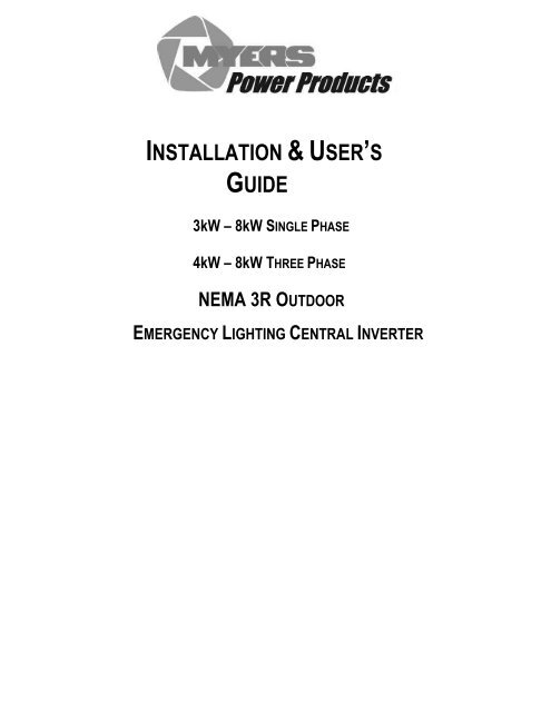
INSTALLATION & USER’S<br />
GUIDE<br />
3kW – 8kW SINGLE PHASE<br />
4kW – 8kW THREE PHASE<br />
NEMA 3R OUTDOOR<br />
EMERGENCY LIGHTING CENTRAL INVERTER
This unit contains LETHAL VOLTAGES. All repairs and service should be performed by<br />
AUTHORIZED SERVICE PERSONNEL ONLY! There are NO USER SERVICEABLE<br />
PARTS inside this unit.<br />
IMPORTANT SAFEGUARDS<br />
When using electrical equipment, you should always follow basic safety<br />
precautions, including the following:<br />
1. READ AND FOLLOW ALL SAFETY<br />
INSTRUCTIONS.<br />
2. Do not install near gas or electric heaters or in other high-temperature<br />
locations.<br />
3. Use caution when servicing batteries. Depending on battery type, batteries<br />
contain either acid or alkali and can cause burns to skin and eyes. If<br />
battery fluid is spilled on skin or in the eyes, flush with fresh water and<br />
contact a physician immediately.<br />
4. Equipment should be mounted in locations where unauthorized personnel<br />
will not readily subject it to tampering.<br />
5. The use of accessory equipment not recommended by Manufacturer may<br />
cause an unsafe condition and void the warranty.<br />
6. Do not use this equipment for other its than intended use.<br />
7. Qualified service personnel must perform all servicing of this equipment.<br />
SAVE THESE INSTRUCTIONS<br />
The installation and use of this product must comply with all national, federal,<br />
state, municipal, or local codes that apply. If you need help, please call<br />
Service.<br />
1<br />
114306E—Install/User <strong>Manual</strong>
C A U T I O N<br />
READ ENTIRE MANUAL AND REVIEW ALL DOCUMENTATION BEFORE ATTEMPTING SYSTEM<br />
INSTALLATION!<br />
FOR YOUR PROTECTION....<br />
PLEASE COMPLETE AND RETURN WARRANTY REGISTRATION CARD IMMEDIATELY.<br />
2<br />
114306E—Install/User <strong>Manual</strong>
TABLE OF CONTENTS<br />
SECTION 1<br />
page(s)<br />
Safety Warning……………………………………………………………………….… 5<br />
Battery Storage Warning……………………………………………………………... 6<br />
SECTION 2<br />
Introduction…………………………………………………………………………….7-9<br />
SECTION 3<br />
Before installing the system………………………………………………...……10-13<br />
<strong>Installation</strong> Dimensions and clearances<br />
Location Guidelines<br />
Storage and operating Environment<br />
<strong>Installation</strong> overview<br />
SECTION 4<br />
AC input & AC output <strong>Installation</strong>…………………………………………………14-17<br />
SECTION 5<br />
Installing batteries and DC wiring……………………………………………....18-29<br />
Safety instructions<br />
Before installing the batteries<br />
Installing and connecting the batteries<br />
Replacing the batteries<br />
Battery interconnect diagrams<br />
SECTION 6<br />
Startup and shutdown procedure……………………………………….………30-32<br />
Maintenance bypass for non-break systems<br />
SECTION 7<br />
Operation…………………………………………………………………………..……...33<br />
SECTION 8<br />
Front panel display…………………………………………………………………..34-38<br />
Control panel keypads<br />
Meter functions<br />
Control functions<br />
Program functions<br />
Automatic tests<br />
3<br />
114306E—Install/User <strong>Manual</strong>
SECTION 9<br />
Options……………………………………………………………………….……...39-43<br />
Output circuit breaker(s)<br />
Summary dry contact<br />
Remote summary alarm panel<br />
Remote panel meter<br />
SECTION 10<br />
RS232 operation……………………………………………………………………44-57<br />
Introduction<br />
Connection<br />
Protocol<br />
Commands<br />
Control functions<br />
Hyper terminal setup<br />
Configuring ZOOM modem<br />
Dialing ZOOM modem<br />
SECTION 11<br />
Specifications………………………………………………………………………….58<br />
SECTION 12<br />
Maintenance and service…………………………………………………………59-60<br />
Trouble shooting chart<br />
SECTION 13<br />
Heater Option <strong>Installation</strong> and Operation…………………………….……….61-62<br />
SECTION 14<br />
Anchor Bolt Placement……………….……………………..………..….…………..63<br />
SECTION 15<br />
Warranty………………………………….……………………………..….……….64-65<br />
4<br />
114306E—Install/User <strong>Manual</strong>
SECTION 1<br />
SAFETY WARNINGS<br />
Read the following precautions before you install this emergency lighting system.<br />
IMPORTANT SAFETY INSTRUCTIONS<br />
SAVE THESE INSTRUCTIONS. This manual contains important instructions that you should<br />
follow during installation and maintenance of the system and batteries. Please read all instructions<br />
before operating the equipment and save this manual for future reference.<br />
DANGER<br />
This system contains LETHAL VOLTAGES. AUTHORIZED SERVICE PERSONNEL should<br />
perform all repairs and service ONLY. There is NO USER SERVICEABLE PARTS inside the<br />
UPS.<br />
WARNING<br />
• Do not install near gas or electric heaters or in other high-temperature locations.<br />
• Use caution when servicing batteries. Battery acid can cause burns to skin and eyes. If acid is<br />
spilled on skin or in the eyes, flush with fresh water and contact a physician immediately.<br />
• Equipment should be mounted in locations where it is not readily subjected to tampering by<br />
unauthorized personnel.<br />
• The use of accessory equipment not recommended by the manufacturer may cause an unsafe<br />
condition.<br />
• Do not use this equipment for other than intended use.<br />
• Only qualified service personnel (such as a licensed electrician) should perform the system and<br />
battery installation and initial startup. Risk of electrical shock.<br />
5<br />
114306E—Install/User <strong>Manual</strong>
BATTERY STORAGE WARNING<br />
This shipment contains rechargeable, maintenance free batteries. They must be stored<br />
properly to assure proper operation upon installation. Therefore, please follow the following<br />
guidelines when storing batteries:<br />
1) Store in clean, dry and cool location. While it is safe to store batteries in environments<br />
of -18 to 40 degrees C (0 to 104 degrees F), it is recommended that you do not store at<br />
temperatures above 30 degrees C (86 degrees F). The warmer the ambient<br />
temperature, the higher the self discharge rate of the battery. This will require more<br />
frequent recharge of the individual batteries until they are placed in service.<br />
2) Avoid storing in direct sunlight or in front of or near heaters, heat duct or other sources<br />
of heat.<br />
3) Do not store directly on concrete structures. Always store on wooden pallets or metal<br />
shelves near floor level.<br />
4) Place the batteries in service within 180 days of receipt. If you cannot place the<br />
batteries in service within the 180 days, then the batteries must be recharged every 180<br />
days, (more frequently if stored at elevated temperatures) while in storage. Failure to do<br />
so will void the warranty and may cause irreversible damage to the battery.<br />
6<br />
114306E—Install/User <strong>Manual</strong>
SECTION 2<br />
INTRODUCTION<br />
Keep this Guide in the folder mounted inside the unit.<br />
This unit is a microprocessor controlled PWM (Pulse Width Modulated) pure sine wave<br />
based DC to AC power inverter utilizing IGBT technology. It integrates a fully automatic 3-<br />
rate battery charger, a solid-state transfer system, control circuitry, self testing and recording<br />
digital meter display, and maintenance free sealed lead calcium type batteries. The system<br />
components are carefully matched to make the unit a completely self-contained, fully<br />
automatic standby power source for operation on all types of lighting loads. The batteries<br />
are sized and tested per UL-924 and Life Safety Code ANSI / NFPA 101, providing<br />
emergency power for a minimum of 90 minutes.<br />
If the duration of a power failure is greater than the batteries storage capability, the inverter<br />
will automatically shut down when the battery voltage reaches 85% of the nominal DC<br />
voltage. This feature protects the battery from being permanently damaged from a deep<br />
discharge that could cause cell reversal. This battery protection feature is called "Low<br />
Voltage Disconnect" or L.V.D.<br />
When the AC power is restored after a full discharge, the system will be ready for another<br />
power failure within 24hrs. If another power failure occurs before the 24-hour recharge time,<br />
the run time will be decreased.<br />
The front panel display incorporates an alphanumeric 2x20 LCD character display, LED<br />
status indicators and a 4 x 4 keypad. All user interface functions are available from the front<br />
panel assembly.<br />
Utilizing a small footprint, this unit is for use with any lighting load including quartz, HID,<br />
incandescent, and fluorescent and halogen.<br />
HOW TO USE THIS MANUAL<br />
This manual tells you how to install, start, operate, and communicate with your unit and lets<br />
you know how to get more information for special situations.<br />
Please record your unit’s part number, serial number, and model number below. You can<br />
find these numbers on the labels on the inside panel.<br />
Part Number __________________________<br />
Serial Number __________________________<br />
Model Number ___________________________<br />
7<br />
114306E—Install/User <strong>Manual</strong>
Record Keeping<br />
An on-site permanent log of the inspection, testing, and maintenance of the emergency<br />
electrical power supply system shall be maintained in accordance with this manual.<br />
The log shall include:<br />
The date on which the inspection, testing, and maintenance exercise was carried out.<br />
The name of the person(s) who performed the inspection, testing, and maintenance.<br />
A note of any unsatisfactory condition observed or discovered, and the steps taken to<br />
correct the condition.<br />
8<br />
114306E—Install/User <strong>Manual</strong>
Service and Support<br />
We are committed to outstanding customer service. A service technician is<br />
available 24 hours a day, 365 days a year. Service is also available 24 hours a day to give<br />
you access to technical notes and product information.<br />
NOTE: Please have your unit’s Serial and Part numbers available when you call; this<br />
number is located behind the right door.<br />
9<br />
114306E—Install/User <strong>Manual</strong>
SECTION 3<br />
BEFORE INSTALLING THE SYSTEM<br />
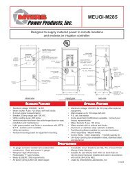
<strong>Installation</strong> Dimensions and Clearances<br />
Figure 3.1 System Dimensions<br />
Table 3.1 Dimensions<br />
Unit<br />
Height<br />
(A)<br />
Width<br />
(B)<br />
Depth<br />
(C)<br />
(D) (E) (F)<br />
Unit<br />
Cabinet<br />
76”<br />
(193 cm)<br />
48”<br />
(122 cm)<br />
30”<br />
(76.2 cm)<br />
19”<br />
(48.3 cm)<br />
13”<br />
(33 cm)<br />
6 1/8”<br />
(15.56 cm)<br />
Table 3.2 Required Clearances<br />
Sides Top Front<br />
0”<br />
(0.0 cm)<br />
0”<br />
(0.0 cm)<br />
Table 3.3 Conduit Knockouts<br />
All<br />
¾”<br />
(1.91 cm)<br />
48”<br />
(122 cm)<br />
10<br />
114306E—Install/User <strong>Manual</strong>
Location Guidelines:<br />
CAUTION<br />
• Choose a permanent location for the unit. Attempting to move them after you have<br />
installed the batteries can damage the batteries and the cabinet.<br />
This equipment is heavy. Refer to Table 3.4 when you choose a site to make sure that the floor<br />
can support the weight of the system, the batteries, and any other necessary equipment.<br />
Table 3.4 System weight [in lbs. (kg)]<br />
System Models for 90 Minute run time<br />
Unit with Standard<br />
SLC Batteries<br />
Unit without<br />
Batteries<br />
Single Phase<br />
Three Phase<br />
3.0kw 4.0kw 5.0kw 6.5kw 8.0kw 4.0kw 5.0kw 6.5kw 8.0kw<br />
1545<br />
(696)<br />
805<br />
(362)<br />
1693<br />
(763)<br />
805<br />
(362)<br />
1990<br />
(896)<br />
805<br />
(362)<br />
2285<br />
(1029)<br />
805<br />
(362)<br />
2580<br />
(1162)<br />
805<br />
(362)<br />
1693<br />
(763)<br />
805<br />
(362)<br />
1990<br />
(896)<br />
805<br />
(362)<br />
2285<br />
(1029)<br />
805<br />
(362)<br />
2580<br />
(1162)<br />
805<br />
(362)<br />
11<br />
114306E—Install/User <strong>Manual</strong>
Receiving and Moving the Unit and the Batteries<br />
Systems weigh several hundred pounds; (see Table 3.4; ask your sales representative for additional<br />
information). Make sure you are prepared for these weights before you unload or move the unit or the<br />
batteries. Do not install any batteries until you have permanently installed the unit and any battery<br />
cabinets and connected all conduit and wiring.<br />
Storage and Operating Environment<br />
Make sure you store the system in a clean, cool, dry place with normal ventilation and level floors.<br />
Storage Temperature<br />
Store the batteries (in the system) at -18 to 40°C (0 to 104°F). Batteries have a longer shelf life if they<br />
are stored below 25°C (77°F). Keep stored batteries fully charged. Recharge the batteries every 90–<br />
180 days. The system without batteries may be stored at -20 to 70°C (-4 to 158°F).<br />
Ventilation<br />
The air around the unit must be clean, dust-free, and free of corrosive chemicals or other<br />
contaminants. Do not place the system or batteries in a sealed room or container.<br />
Operating Temperature<br />
System can operate from -20 to 40° (-4 to 104°F) and up to 95% relative humidity. The batteries’<br />
service life is longer if the operating temperature stays below 25°C (77°F).<br />
Batteries<br />
The temperature should be near 25°C (77°F) for optimum battery performance. Batteries are less<br />
efficient at temperatures below 18°C (65°F), and high temperatures reduce battery life. Typically, at<br />
about 35°C (95°F), battery life is half of what it would be at a normal temperature of 25°C (77°F). At<br />
about 45°C (113°F), battery life is one-fourth of normal.<br />
Make sure that heaters, sunlight, air conditioners, or outside air vents are not directed toward the<br />
batteries. These conditions can make the temperature within battery strings vary, which can cause<br />
differences in the batteries’ voltages. Eventually, these conditions affect battery performance.<br />
If the batteries are not in the system, remember that the batteries should be installed as close as<br />
possible to the unit to reduce DC wiring costs and improve battery performance.<br />
Do not allow tobacco smoking, sparks, or flames in the system location because hydrogen is<br />
concentrated under the vent cap of each cell of the battery. Hydrogen is highly explosive, and it is<br />
hard to detect because it is colorless, odorless, and lighter than air.<br />
Every type of battery can produce hydrogen gas, even sealed maintenance-free batteries. The gas is<br />
vented through the vent caps and into the air, mainly when the unit is charging the batteries. The<br />
batteries produce the most hydrogen when maximum voltage is present in fully charged batteries.<br />
The amount of current that the charger supplies to the batteries (not the battery ampere-hour)<br />
determines how much hydrogen is produced.<br />
High Altitude Operation<br />
The maximum operating ambient temperature drops 1°C per 300m (2°F per 1000 ft) above sea level.<br />
Maximum elevation is 3000m (10,000 ft).<br />
12<br />
114306E—Install/User <strong>Manual</strong>
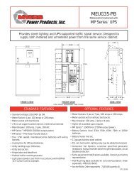
INSTALLATION OVERVIEW<br />
Figure 3.2 shows typical installations of system.<br />
Building<br />
Service<br />
Panel<br />
To<br />
Supported<br />
Loads<br />
Fig 3.2 Typical Hardwire <strong>Installation</strong><br />
Bottom access<br />
thru removable<br />
panels<br />
(See Section 14 for Anchor Bolt Placement)<br />
13<br />
114306E—Install/User <strong>Manual</strong>
SECTION 4<br />
AC INPUT & AC OUTPUT INSTALLATION<br />
WARNING<br />
Only qualified service personnel (such as a licensed electrician) should perform the AC<br />
installation. Risk of electrical shock.<br />
Read the following cautions before you continue.<br />
CAUTION<br />
• Unit contains hazardous AC and DC voltages. Because of these voltages, a qualified<br />
electrician must install the system, AC line service, and batteries. The electrician must<br />
install the AC line service according to local and national codes and must be familiar<br />
with batteries and battery installation.<br />
• Before you install, maintain, or service the unit, always remove or shut off all sources of<br />
AC and DC power and shut off the system. You must disconnect AC line input at the<br />
service panel and turn off the <strong>Installation</strong> Switch (S1), the Main AC Input Circuit<br />
Breaker (CB1), and the Battery Fuse(s) to make sure the unit does not supply output<br />
voltage.<br />
• Whenever AC and/or DC voltage is applied, there is AC voltage inside the unit; this is<br />
because the unit can supply power from AC line or from its batteries. To avoid<br />
equipment damage or personal injury, always assume that there may be voltage inside<br />
the unit.<br />
• Remove rings, watches, and other jewelry before installing the AC wiring. Always wear<br />
protective clothing and eye protection and use insulated tools when working near<br />
batteries. Whenever you are servicing an energized unit with the inside panel open,<br />
electric shock is possible; follow all local safety codes. TEST BEFORE TOUCHING!<br />
1. Open the unit’s doors. Make sure the installation switch and the input circuit breaker are off, and<br />
the battery fuse removed inside the unit.<br />
2. Look at the ID label on the inside right door. Write down the following information:<br />
Input Voltage: ___________<br />
Output Voltage: ___________<br />
3. Now, make sure the input and output voltages are what you need.<br />
• Does the input voltage available for the system at the AC service panel match the input<br />
voltage shown on the unit’s ID label?<br />
Service Panel Voltage = _____________ Input Voltage ___Yes /___No<br />
• Does the output voltage on the ID label match the voltage your loads (protected equipment)<br />
need?<br />
Load Voltage = ______________ Output Voltage ___Yes/___No<br />
If you answered NO to either of the preceding questions, call SERVICE.<br />
14<br />
114306E—Install/User <strong>Manual</strong>
4. Now, use the information you wrote down in Step 2 to find the correct circuit breaker for the<br />
service panel that is for your system.<br />
Table 4.1 Recommended Circuit Breaker for Maximum Input Current<br />
System Input Voltage (Vac) Max. Current Recommended<br />
Circuit Breaker<br />
3.0kW 120V 32 amps 40A, 1-Pole<br />
3.0kW 277V 14 amps 20A, 1-Pole<br />
4.0kW 120V 42 amps 50A, 1-Pole<br />
4.0kW **208V 24 amps 30A, 2-Pole<br />
4.0kW **240V 21 amps 30A, 2-Pole<br />
4.0kW 277V 18 amps 25A, 1-Pole<br />
4.0kW 120/208V 14 amps 20A, 3-Pole<br />
4.0kW 277/480V 6 amps 10A, 3-Pole<br />
5.0kW 120V 52 amps 70A, 1-Pole<br />
5.0kW **208V 30 amps 40A, 2-Pole<br />
5.0kW **240V 26 amps 35A, 2-Pole<br />
5.0kW 277V 23 amps 30A, 1-Pole<br />
5.0kW 120/208V 17 amps 25A, 3-Pole<br />
5.0kW 277/480V 8 amps 10A, 3-Pole<br />
6.5kW 120V 68 amps 90A, 1-pole<br />
6.5kW **208V 39 amps 50A, 2-Pole<br />
6.5kW **240V 34 amps 45A, 2-Pole<br />
6.5kW 277V 29 amps 40A, 1-Pole<br />
6.5kW 120/208V 23 amps 30A, 3-Pole<br />
6.5kW 277/480V 10 amps 15A, 3-Pole<br />
8.0 kW 120V 84 amps 100A, 1-Pole<br />
8.0 kW **208V 48 amps 60A, 2-Pole<br />
8.0 kW **240V 42 amps 50A, 2-Pole<br />
8.0 kW 277V 36 amps 45A, 1-Pole<br />
8.0 kW 120/208V 28 amps 35A, 3-pole<br />
8.0 kW 277/480V 12 amps 15A, 3-pole<br />
** WARNING: THE EXTERNAL INPUT CIRCUIT BREAKER PROTECTING THE SYSTEM MUST<br />
BE A “MOTOR START”, DELAYED TRIP TYPE. THIS IS DUE TO MAGNETIC INRUSH<br />
CURRENT DRAWN DURING APPLICATION OF AC POWER. PLEASE NOTE THAT<br />
THIS APPLIES TO ANY UNIT THAT HAS A DIFFERENCE BETWEEN THE INPUT AND<br />
THE OUTPUT VOLTAGES.<br />
5. Write down the circuit breaker value that applies to your system from Table 4.1:<br />
___________<br />
6. Now, refer to Table 4.2 and use the notes to find the proper gauge wire for the<br />
recommended circuit breaker recorded in step 5.<br />
15<br />
114306E—Install/User <strong>Manual</strong>
Table 4.2 Recommended Minimum Wire Sizes<br />
Read These Important Notes! For this Input Use this Size 90°C<br />
Circuit Breaker Copper Wire<br />
Size...<br />
This table lists the AWG and mm2 wire size for each circuit breaker size.<br />
The minimum recommended circuit breaker sizes for each model and<br />
voltage application are listed in Table 4.1. The temperature rating of<br />
conductor must not be less than 90° C wire. Based on the ampacities<br />
given in Tables 310-16 of the National Electrical Code, ANSI/NFPA 70-<br />
1993 (Table 2 of the CEC), and NEC article 220 (CEC Section 4). Circuit<br />
conductors, must be the same size (ampacity) wires and equipmentgrounding<br />
conductors must meet Table 250-95 of the National Electrical<br />
Code. Code may require a larger wire size than shown in this table<br />
because of temperature, number of conductors in the conduit, or long<br />
service runs. Follow local code requirements.<br />
AWG mm 2<br />
10, 15, 20 12 3.31<br />
25, 30 10 5.26<br />
35, 40, 45 8 8.36<br />
50, 60 6 13.30<br />
70, 80 4 21.15<br />
90, 100 2 33.62<br />
7. The input circuit breaker in the input service panel provides the means for disconnecting<br />
AC to the unit. Only authorized persons shall be able to disconnect AC to the unit [see NEC 700-<br />
20 and 700-21(CEC Section 46)]. If you are using the input circuit breaker to disconnect AC, you<br />
must make sure that only authorized persons have control of the circuit breaker panel to meet<br />
the requirements of NEC 700-20 (CEC Section 46).<br />
8. Read the following caution, before removing conduit knockouts.<br />
CAUTION<br />
To prevent electrical shock or damage to your equipment, the <strong>Installation</strong> Switch (S1), the Main<br />
AC Input Circuit Breaker (CB1), and the circuit breaker at the input service panel should all be<br />
turned off. The Main DC Battery Fuse and the external DC Disconnect Fuse(s) (if you have<br />
one) should be removed.<br />
9. Remove knockouts for AC Input and AC Output in the right or left side of the system. AC<br />
input conductors and AC output conductors must be installed in separate conduits, and<br />
emergency and non-emergency output circuits must be installed in separate conduits.<br />
CAUTION<br />
Do not drill the cabinet; drill filings may damage the unit and keep it from operating. If you<br />
need larger knockouts, use a chassis punch to punch out the appropriate knockout. Do not<br />
create additional knockouts.<br />
10. Install the conduit. You must run the AC input service conductors and AC output conductors<br />
through separate conduits. Emergency output conductors and non-emergency output conductors<br />
must also be run through separate conduits. Emergency output circuits shall be installed in<br />
dedicated conduit systems and not shared with other electrical circuits as described in NEC 700-<br />
9(b) [CEC Section 47-108].<br />
The next step explains where to make the AC connections to the system.<br />
INSTALLING AC INPUT WIRES:<br />
11. Connect AC utility from the service panel to the system’s terminal block labeled “INPUT”.<br />
For 2-wire input: connect hot wire to the input block marked “Line”, connect the common wire<br />
16<br />
114306E—Install/User <strong>Manual</strong>
to the input block marked “Neutral” and connect the ground wire to the compression lug next to<br />
the input terminal block. For 3-wire input: connect each hot wire to each of the input block<br />
positions marked “Line”, connect the common wire to the input block marked “Neutral” and the<br />
ground wire to the compression lug next to the input terminal block. For 4-wire input: connect<br />
each hot wire to each of the input blocks marked “Line”. Phasing must be clockwise rotation –<br />
i.e. Phase B lags Phase A, connect the common wire to the input block marked “Neutral” and<br />
ground wire to the compression lug next to the input terminal block.<br />
INSTALLING AC OUTPUT WIRES:<br />
12. Connecting load wires without system distribution circuit breakers – connect load wires to the<br />
system’s terminal block labeled “OUTPUT”. Connect hot wire(s) to the output block marked<br />
“Nor. On”, the common wire(s) to the output block marked “Neutral” and the ground wire(s) to<br />
the compression lug next to the output terminal block. Emergency only load hot wires must be<br />
connected to the optional circuit on the output terminal block labeled “Nor. Off”.<br />
Connecting load wires with system distribution circuit breakers – connect the hot wire from each<br />
branch circuit to a circuit breaker and connect the common wire from each branch circuit to the<br />
neutral connection bar.<br />
Figure 4.1 AC Input and Output connections<br />
17<br />
114306E—Install/User <strong>Manual</strong>
SECTION 5<br />
INSTALLING BATTERIES AND DC WIRING<br />
WARNING<br />
Only qualified service personnel (such as a licensed electrician) should perform the<br />
battery and DC wiring installation. Risk of electrical shock.<br />
This section explains how to install system batteries, fuses, and cables. An electrician who is<br />
familiar with battery installations and applicable building and electrical codes should install<br />
the batteries.<br />
WARNING<br />
The batteries that will need to be installed in this system could cause you harm or severely<br />
damage the electronics if proper precautions are not followed. Batteries connected in series<br />
parallel configuration could produce lethal voltages with extreme currents. All batteries<br />
should be inspected for damage prior to installation. Never install a battery that is leaking<br />
electrolyte. Battery terminals should be cleaned with a wire brush to remove any oxidation.<br />
All tools should be insulated. Rubber gloves and safety glasses are recommended. IN THIS<br />
SYSTEM BATTERY NEGATIVE IS TIED TO GROUND INSIDE THE INVERTER. This<br />
means that the battery cabinet and shelves are at ground potential as soon as negative<br />
connections are made to the batteries. It is strongly recommended to make all negative<br />
connections to the batteries the last step to prevent any chance of shorting battery positive to<br />
ground. With the DC fuse removed, make connections to battery positive first, working your<br />
way towards battery negative. Leave individual strings of batteries open at the last battery<br />
negative until all batteries are installed. Then connect each strings negative.<br />
Safety Instructions<br />
IMPORTANT SAFETY INSTRUCTIONS<br />
SAVE THESE INSTRUCTIONS<br />
This section contains important instructions that a qualified service person should<br />
follow during installation and maintenance of the system and batteries. ONLY a<br />
qualified service person should work with the batteries.<br />
CAUTION<br />
Full voltage and current are always present at the battery terminals. The batteries used<br />
in this system can produce dangerous voltages, extremely high currents, and a risk of<br />
electric shock. They may cause severe injury if the terminals are shorted together or to<br />
ground (earth). You must be extremely careful to avoid electric shock and burns<br />
caused by contacting battery terminals or shorting terminals during battery installation.<br />
Do not touch un-insulated battery terminals.<br />
18<br />
114306E—Install/User <strong>Manual</strong>
A qualified electrician familiar with battery systems and required precautions must<br />
install and service the batteries. Any battery used with this unit shall comply with the<br />
applicable requirements for batteries in the standard for emergency lighting and power<br />
equipment, UL 924 (Canada’s National Building Code). Cabinets are design to be used<br />
with, and batteries must be replaced with, manufacturer battery number BAT-CG12105<br />
or a manufacturer approved equivalent (see the battery wiring diagram that came with<br />
the battery cables). If you substitute batteries not supplied by manufacturer, the unit’s<br />
UL (cUL) listing is void and the equipment may fail. <strong>Installation</strong> must conform to<br />
national and local codes as well. Keep unauthorized personnel away from batteries.<br />
The electrician must take these precautions:<br />
Wear protective clothing and eyewear. For battery systems >48vdc, wear rubber<br />
gloves and boots. Batteries contain corrosive acids or caustic alkalis and toxic<br />
materials and can rupture or leak if mistreated. Remove rings and metal wristwatches<br />
or other metal objects and jewelry. Don’t carry metal objects in your pockets where the<br />
objects can fall onto the batteries or into the system or battery cabinet.<br />
Tools must have insulated handles and must be insulated so that they do not short<br />
battery terminals. Do not allow a tool to short a battery terminal to another battery<br />
terminal or to the cabinet at any time. Do not lay tools or metal parts on top of the<br />
batteries, and do not lay them where they could fall onto the batteries or into the<br />
cabinet.<br />
Install the batteries as shown on the battery-wiring diagram provided with the system.<br />
When connecting cables, never allow a cable to short across a battery’s terminals, the<br />
string of batteries, or to the cabinet.<br />
Align the cables on the battery terminals so that the cable lug does not contact any part<br />
of the cabinet even if the battery is moved. Keep the cable away from any sharp metal<br />
edges.<br />
CAUTION<br />
Install the battery cables so the system dead front panels cannot pinch them.<br />
Where conductors may be exposed to physical damage, protect conductors in<br />
accordance with the National Electrical Code (NEC) [Canadian Electrical Code (CEC)].<br />
If you are replacing batteries or repairing battery connections, follow the procedure in<br />
the section 6 to shut down your system and remove both AC and DC input power.<br />
19<br />
114306E—Install/User <strong>Manual</strong>
Before Installing the Batteries<br />
Tools<br />
CAUTION<br />
Always use insulated tools when you work with batteries. Always torque connections to<br />
the manufacturer’s recommendations.<br />
When you work with system batteries, you need the following tools. The tools must<br />
be insulated so they do not short battery terminals to the cabinet. Wear the safety<br />
equipment required by local code whenever the doors are open and whenever you<br />
are working on batteries. Other tools may be necessary for optional batteries.<br />
• Digital volt-ohm meter<br />
• 7/16” open end wrench<br />
• 3” extension socket<br />
• Ratchet<br />
• Wire brush<br />
• Electrical tape<br />
• Conductive grease or petroleum jelly<br />
• Brush (to apply grease or petroleum jelly to terminals)<br />
• Safety equipment required by local codes<br />
• Torque wrench calibrated in inch-pounds or Newton-meters<br />
• 7/16” socket wrench<br />
• Safety glasses with side shields<br />
Battery Voltage (vdc)<br />
Models 3.0kW 4.0kW 5.0kW 6.5kW 8.0kW<br />
Battery Volts for 90<br />
Minute Systems<br />
120v 144v 180v 240v 144v<br />
Battery Cable Sizing<br />
The battery cable or wire used is No. 6 AWG (13.30 mm 2 ) for all applications:<br />
DC Disconnect<br />
Systems have a Main Battery Fuse (F1) inside the cabinet; this fuse lets you remove DC<br />
power from the batteries. Systems with two parallel sets of batteries have a fuse in line with<br />
the positive cable of each string.<br />
Installing and Connecting the Batteries<br />
Battery Wiring Diagram<br />
Refer to the “Battery Interconnect” diagram (pgs.25-29) that corresponds with your systems<br />
KVA rating. This battery-wiring diagram shows how you should install the batteries, make<br />
terminal, and fuse connections. Use the diagram as you follow the steps below.<br />
Location<br />
The system batteries are inside the unit. Before you start installing the batteries, you must<br />
install the system in its permanent location. If you have not already done this, see “Location<br />
Guidelines” on page 11 to choose a location.<br />
20<br />
114306E—Install/User <strong>Manual</strong>
CAUTION<br />
To prevent damage to your equipment, do not move the system after the batteries are<br />
installed.<br />
To make sure a location is acceptable for the system, review the requirements in Section 3.<br />
Electronics Cabinet Battery Block Connections<br />
Do not connect any battery cables at this time. In the following procedure, you should<br />
only make connections to the electronics cabinet’s battery block. Use the battery-wiring<br />
diagram shipped with the battery cables as you follow these steps.<br />
1. For systems with a single string of batteries: Find the positive battery cable<br />
that connects to the battery block. At the bare end of the cable, strip off 0.5” (1.3<br />
cm) of insulation. Connect the cable to the battery block. Torque the connection<br />
as shown on the battery-wiring diagram. Insulate the other end of the cable. For<br />
systems with two strings of batteries (8kW only): Repeat this step with<br />
second positive battery cable.<br />
2. For systems with a single string of batteries: Find the negative battery cable<br />
that connects to the battery block. At both ends of the cable, strip off 0.5” (1.3<br />
cm) of insulation. Connect one end of the cable to the battery block, the other<br />
end to the fuse block on the battery shelf. Torque the connection as shown on<br />
the battery-wiring diagram. For systems with two strings of batteries (8kW<br />
only): Repeat this step with second negative battery cable.<br />
Fuse<br />
All units come with a fuse(s) to protect the system. The battery-wiring diagram<br />
shows the fuse location; a label inside the battery cabinet shows the fuse size.<br />
Verify that the battery fuse(s) in the cabinet is removed before connecting<br />
the batteries.<br />
Arranging the Batteries<br />
NOTE As you arrange the batteries, you must be wearing the required safety<br />
equipment.<br />
Arrange the batteries in the cabinet or the system only as shown in the battery-wiring<br />
diagram. This arrangement is designed to maximize airflow around the batteries. The<br />
cabinets are designed so that battery cases should never touch. Air should be free to<br />
circulate. Clean the entire surface of all battery terminals with the wire brush before you<br />
install the batteries to create good contact points.<br />
Load the batteries into the system or battery cabinet(s). Starting with the bottom shelf,<br />
load one shelf at a time.<br />
CAUTION<br />
Never install the batteries in an airtight enclosure.<br />
21<br />
114306E—Install/User <strong>Manual</strong>
Connecting the Cables Between Batteries<br />
When you make battery terminal connections, use the torque wrench to tighten the<br />
battery terminal connections securely. For most batteries, you can find out what torque<br />
value to use by finding the battery number on the front of the battery. Then, use Table 5.1<br />
to find the torque value for that battery.<br />
Now, follow these steps to connect the cables:<br />
Table 5.1 Battery Torque<br />
Battery Type<br />
SL-12105<br />
SL-12105M<br />
BAT-CG12105<br />
BAT-CG12105A<br />
Torque<br />
Torque to 120 in lbs. (13.6 Nm)<br />
Torque to 120 in lbs. (13.6 Nm)<br />
Torque to 120 in lbs. (13.6 Nm)<br />
Torque to 120 in lbs. (13.6 Nm)<br />
1. Using the battery-wiring diagram, determine which batteries belong to each<br />
battery string.<br />
NOTE: For standard 90-minute runtimes, 3kW, 4kW, 5kW, 6.5kW models have only<br />
one battery string. 8kW models have two battery strings.<br />
2. Clean the cable connectors with the wire brush before you make the battery<br />
connections.<br />
NOTE As you carry out the following step, use these guidelines:<br />
If you are using conductive grease, apply a thin coating of high-temperature<br />
conductive grease on each post and every cable connector before you assemble<br />
and torque the connection to slow corrosion.<br />
If you use nonconductive grease like petroleum jelly, do not apply any grease<br />
before you make the connections and torque them. Instead, make the connection<br />
first; then, torque it to the value shown in Table 5.1. After you make the connection,<br />
apply a coating of the nonconductive grease to the hardware at the battery<br />
terminals.<br />
3. In each battery string, connect the battery cables between the batteries as<br />
shown in the battery-wiring diagram (positive terminal to negative terminal).<br />
Torque the connections to the value shown for your battery in Table 5.1.<br />
4. Connect the battery cables from one shelf to the next as shown on the batterywiring<br />
diagram.<br />
5. Connect the fuse block to the negative of the battery as shown on the batterywiring<br />
diagram.<br />
CAUTION<br />
Hazardous voltage is present! System batteries are high current sources. These<br />
batteries can produce dangerous voltages, extremely high currents, and a risk of<br />
electric shock.<br />
22<br />
114306E—Install/User <strong>Manual</strong>
6. Install only the battery string fuses( on the battery shelf). Next, use the voltmeter<br />
to check the DC voltage between the negative (-) position on the battery block<br />
and the unconnected battery positive terminal. This voltage should be<br />
approximately the battery voltage record on the unit ID label. If it is greater than<br />
+ or – 5% Vdc, review the battery wiring diagram. Correct any wiring errors and<br />
recheck the DC voltage; do not go on until your measurement is within + or –<br />
5% Vdc. If the measurement is too high and you cannot find the cause of the<br />
problem, call SERVICE.<br />
CAUTION<br />
If you do not verify that voltage and current direction are correct, the equipment may<br />
fail.<br />
Connecting the Positive Battery Cable(s) to the Battery String(s)<br />
Remove the insulation from the cable that was put on in step 2 of “Electronics<br />
cabinet battery block connections”. Connect the cable to the battery positive (+).<br />
Repeat this step for systems with 2 strings.<br />
Replacing the Batteries<br />
CAUTION<br />
A battery can present a risk of electrical shock and high short circuit current. A qualified<br />
electrician familiar with battery systems should service the batteries.<br />
Review all the safety instructions at the beginning of this chapter before you replace any<br />
batteries.<br />
Use the Same Quantity and Type of Battery<br />
CAUTION<br />
You must use the same quantity and type of battery. Substituting batteries not supplied<br />
by manufacturer voids the UL (CUL) listing and may cause equipment damage.<br />
To ensure continued superior performance of your system and to maintain proper charger<br />
operation, you must replace the batteries in the system or battery cabinets with the same<br />
number of batteries. These batteries must be the same types as the original batteries. The<br />
replacement batteries should have the same voltage and ampere-hour rating as the original<br />
batteries.<br />
Handle Used Batteries with Care!<br />
Assume that old batteries are fully charged. Use the same precautions you would use when<br />
handling a new battery. Do not short battery terminals or the battery string with a cable or tool<br />
when you disconnect the batteries! Batteries contain lead. Please dispose of old batteries<br />
properly.<br />
23<br />
114306E—Install/User <strong>Manual</strong>
CAUTION<br />
Do not dispose of batteries in a fire because the batteries could explode. Do not open<br />
or mutilate batteries. Released electrolyte is harmful to the skin and eyes. It may be<br />
toxic.<br />
Dispose of Batteries Properly<br />
CAUTION<br />
Batteries contain lead. Many state and local governments have regulations about used<br />
battery disposal. Please dispose of the batteries properly.<br />
24<br />
114306E—Install/User <strong>Manual</strong>
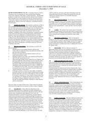
(TB1)<br />
DC FUSE (F3)<br />
BATTERY<br />
INTERCONNECT<br />
(TB3)<br />
INPUT<br />
CIRCUIT BREAKER<br />
(CB1)<br />
AC INPUT AC OUTPUT<br />
INVERTER CABINET<br />
76"H x 48"W x 30"DP.<br />
(TB2)<br />
X<br />
REV. DES<strong>CR</strong>IPTION DATE BY<br />
CAUTION:<br />
2<br />
1<br />
ITEM<br />
NO.<br />
1-<br />
3-<br />
2-<br />
4-<br />
BEFORE WIRING TO INVERTER,<br />
TURN INSTALLATION SWITCH TO OFF<br />
AND REMOVE DC FUSE.<br />
CUT ITEMS 3 - 5 TO MINIMUM LENGTH.<br />
OBSERVE POLARITY, CONNECT BATTERIES<br />
AS SHOWN.<br />
FOLLOW START-UP PROCEDURE IN<br />
SYSTEM MANUAL.<br />
DATE:<br />
INTERCONNECT<br />
ALL DIMENSIONS ARE SHOWN IN INCHES DRAWN BY:<br />
ALL DIM. TOL. .015", ANGULAR ALL DIM. TOL. 1ALL DIM. TOL.<br />
UNLESS OTHERWISE SPECIFIED. APPROVED BY:<br />
08/23/05<br />
120VDC<br />
SCHEMATIC<br />
12VBATTERIES<br />
DES<strong>CR</strong>IPTION<br />
66<br />
BATTERY INTERCONNECT, "C-3R", FRONT MOUNT<br />
10<br />
POS. +<br />
NEG. -<br />
BATTERY RETAINER<br />
BRACKET<br />
- +<br />
6<br />
ELECTRONICS<br />
COMPARTMENT<br />
BATTERY<br />
INTERCONNECT<br />
+<br />
-<br />
2<br />
+<br />
-<br />
+<br />
-<br />
NOTE:<br />
REMOVE BATTERY RETAINER BRACKET BEFORE<br />
AND REPLACE AFTER BATTERY INSTALLATION<br />
INSTALLATION SW<br />
DISCHARGE SW<br />
PRE-CHARGE SW<br />
8<br />
5<br />
+<br />
-<br />
+<br />
-<br />
1<br />
7<br />
2<br />
DOORS, COVERS OMITTED FOR CLARITY<br />
8<br />
3<br />
9<br />
4<br />
10<br />
5<br />
6 7<br />
6 7 8 9 10<br />
1<br />
2<br />
1<br />
3<br />
4<br />
TOP VIEW OF BATTERIES<br />
SHOWN ABOVE<br />
5 BATTERIES PER SHELF<br />
ON 2 SHELVES<br />
5<br />
3<br />
4<br />
4<br />
3.0kVA @ 90 MINUTE RUN TIME<br />
FUSE<br />
CABLE 6 GA. 48 "LG.<br />
6<br />
3 CABLE GA. "LG. 36 1 W - B 0 3 6 + 0 6 0 L 1<br />
3.0k @ 90 MIN.<br />
SL-12105<br />
1<br />
1<br />
8<br />
QTY.<br />
W - B 0 4 8 + 0 6 0 L 1<br />
PART NO.<br />
DRAWING NUMBER:<br />
K W<br />
303399<br />
1 - +<br />
MANUFACTURER PROVIDED<br />
8 BATTERY 10 BAT-CG12105<br />
7 FUSE BLOCK 1 F-B060-0250<br />
6 FNLN050250B<br />
5 CABLE 6 GA. 60"LG. 1 W-B060+060B0<br />
CABLE 6 GA. "LG. 1 W-B066+060L2<br />
SCALE: 1 = 15<br />
+ - +<br />
- - +<br />
+ -<br />
- +<br />
- +<br />
X X X<br />
25<br />
114306E—Install/User <strong>Manual</strong>
BATTERY RETAINER<br />
BRACKET<br />
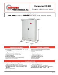
(TB1)<br />
INPUT<br />
CIRCUIT BREAKER<br />
(CB1)<br />
DC FUSE (F3)<br />
BATTERY<br />
INTERCONNECT<br />
(TB3)<br />
POS. +<br />
NEG. -<br />
7 8 9 10 11 12<br />
INVERTER CABINET<br />
76"H x 48"W x 30"DP.<br />
ELECTRONICS<br />
COMPARTMENT<br />
X<br />
BATTERY<br />
INTERCONNECT<br />
+<br />
-<br />
REV. DES<strong>CR</strong>IPTION DATE BY<br />
2<br />
CAUTION:<br />
DATE:<br />
1-<br />
3-<br />
2-<br />
4-<br />
BEFORE WIRING TO INVERTER,<br />
TURN INSTALLATION SWITCH TO OFF<br />
AND REMOVE DC FUSE.<br />
CUT ITEMS 3 - 5 TO MINIMUM LENGTH.<br />
OBSERVE POLARITY, CONNECT BATTERIES<br />
AS SHOWN.<br />
FOLLOW START-UP PROCEDURE IN<br />
SYSTEM MANUAL.<br />
ALL DIMENSIONS ARE SHOWN IN INCHES DRAWN BY:<br />
ALL DIM. TOL. .015", ANGULAR ALL DIM. TOL. 1ALL DIM. TOL.<br />
UNLESS OTHERWISE SPECIFIED. APPROVED BY:<br />
08/23/05<br />
144VDC<br />
SCHEMATIC<br />
12VBATTERIES<br />
3 CABLE 6 GA. "LG.<br />
2 66<br />
1 INTERCONNECT<br />
ITEM<br />
NO.<br />
DES<strong>CR</strong>IPTION<br />
12<br />
- +<br />
+<br />
-<br />
+<br />
-<br />
NOTE:<br />
REMOVE BATTERY RETAINER BRACKET BEFORE<br />
AND REPLACE AFTER BATTERY INSTALLATION<br />
INSTALLATION SW<br />
DISCHARGE SW<br />
PRE-CHARGE SW<br />
8<br />
1<br />
4<br />
+<br />
-<br />
+<br />
-<br />
+<br />
+<br />
-<br />
-<br />
1 2 3 4 5 6<br />
6 7<br />
DOORS, COVERS OMITTED FOR CLARITY<br />
7 8 9 10 11 12<br />
1 2 3 4 5 6<br />
TOP VIEW OF BATTERIES<br />
SHOWN ABOVE<br />
6 BATTERIES PER SHELF<br />
ON 2 SHELVES<br />
3<br />
5<br />
8<br />
4.0kVA @ 90 MINUTE RUN TIME<br />
BATTERY<br />
BATTERY INTERCONNECT, "C-/C3-3R", FRONT MOUNT<br />
4.0kVA @ 90 MIN.<br />
SL-12105<br />
12<br />
10<br />
QTY.<br />
BAT-CG12105<br />
4 CABLE 6 GA. 48"LG. 1 W-B048+060L1<br />
PART NO.<br />
DRAWING NUMBER:<br />
K W<br />
303404<br />
1 - +<br />
MANUFACTURER PROVIDED<br />
7 FUSE BLOCK 1 F-B060-0250<br />
6 FUSE 1 FNLN050250B<br />
5 CABLE 6 GA. 60"LG. 1 W-B060+060B0<br />
36 1 W - B 0 3 6 + 0 6 0 L 1<br />
CABLE 6 GA. "LG. 1 W-B066+060L2<br />
SCALE: 1 = 15<br />
+ - +<br />
- - +<br />
+ -<br />
- +<br />
- +<br />
X X X<br />
AC INPUT AC OUTPUT<br />
(TB2)<br />
26<br />
114306E—Install/User <strong>Manual</strong>
BATTERY RETAINER<br />
BRACKET<br />
DC FUSE (F3)<br />
BATTERY<br />
INTERCONNECT<br />
(TB3)<br />
POS. +<br />
NEG. -<br />
INVERTER CABINET<br />
76"H x 48"W x 30"DP.<br />
COMPARTMENT<br />
ELECTRONICS<br />
X<br />
BATTERY<br />
INTERCONNECT<br />
+<br />
-<br />
REV. DES<strong>CR</strong>IPTION DATE BY<br />
2<br />
CAUTION:<br />
2<br />
1<br />
ITEM<br />
NO.<br />
DATE:<br />
1-<br />
3-<br />
2-<br />
4-<br />
BEFORE WIRING TO INVERTER,<br />
TURN INSTALLATION SWITCH TO OFF<br />
AND REMOVE DC FUSE.<br />
CUT ITEMS 3 - 5 TO MINIMUM LENGTH.<br />
OBSERVE POLARITY, CONNECT BATTERIES<br />
AS SHOWN.<br />
FOLLOW START-UP PROCEDURE IN<br />
SYSTEM MANUAL.<br />
INTERCONNECT<br />
ALL DIMENSIONS ARE SHOWN IN INCHES DRAWN BY:<br />
ALL DIM. TOL. .015", ANGULAR ALL DIM. TOL. 1ALL DIM. TOL.<br />
UNLESS OTHERWISE SPECIFIED. APPROVED BY:<br />
08/23/05<br />
180VDC<br />
SCHEMATIC<br />
12VBATTERIES<br />
DES<strong>CR</strong>IPTION<br />
66<br />
15<br />
- +<br />
+<br />
-<br />
+<br />
-<br />
NOTE:<br />
REMOVE BATTERY RETAINER BRACKET BEFORE<br />
AND REPLACE AFTER BATTERY INSTALLATION<br />
INSTALLATION SW<br />
DISCHARGE SW<br />
PRE-CHARGE SW<br />
8<br />
1<br />
4<br />
+<br />
+<br />
-<br />
-<br />
+<br />
+<br />
-<br />
-<br />
AC INPUT<br />
(TB1)<br />
INPUT<br />
CIRCUIT BREAKER<br />
(CB1)<br />
11 12 13 14 15<br />
6 7 8 9 10<br />
1 2 3 4 5<br />
6 7<br />
(TB2)<br />
AC OUTPUT<br />
DOORS, COVERS OMITTED FOR CLARITY<br />
11 12 13 14 15<br />
6 7 8 9 10<br />
1 2 3 4 5<br />
TOP VIEW OF BATTERIES<br />
SHOWN ABOVE<br />
5 BATTERIES PER SHELF<br />
ON 3 SHELVES<br />
3<br />
5<br />
2<br />
8<br />
5.0kVA @ 90 MINUTE RUN TIME<br />
BATTERY<br />
3 CABLE GA. "LG. 36 1 W - B 0 6 6 + 0 6 0 L 1<br />
BATTERY INTERCONNECT, "C-/C3-3R", FRONT MOUNT<br />
5.0kVA @ 90 MIN.<br />
6<br />
SL-12105<br />
60<br />
15<br />
12<br />
QTY.<br />
BAT-CG12105<br />
4 CABLE 6 GA. 12"LG. 1 W-B012+060L1<br />
PART NO.<br />
DRAWING NUMBER:<br />
K W<br />
303405<br />
1 - +<br />
MANUFACTURER PROVIDED<br />
7 FUSE BLOCK 1 F-B060-0250<br />
6 FUSE 1 FNLN050250B<br />
5 CABLE 6 GA. "LG. 1 W-B060+060B0<br />
CABLE 6 GA. "LG. 2 W-B066+060L2<br />
SCALE: 1 = 15<br />
+ - +<br />
- - +<br />
+ - +<br />
- - +<br />
+ -<br />
- +<br />
- +<br />
X X X<br />
27<br />
114306E—Install/User <strong>Manual</strong>
BRACKET<br />
BATTERY RETAINER<br />
DC FUSE (F3)<br />
BATTERY<br />
INTERCONNECT<br />
(TB3)<br />
POS. +<br />
NEG. -<br />
INVERTER CABINET<br />
76"H x 48"W x 30"DP.<br />
ELECTRONICS<br />
COMPARTMENT<br />
X<br />
BATTERY<br />
INTERCONNECT<br />
+<br />
-<br />
REV. DES<strong>CR</strong>IPTION DATE BY<br />
5<br />
2<br />
CAUTION:<br />
8<br />
2<br />
1<br />
NO.<br />
ITEM<br />
DATE:<br />
1-<br />
3-<br />
2-<br />
4-<br />
BEFORE WIRING TO INVERTER,<br />
TURN INSTALLATION SWITCH TO OFF<br />
AND REMOVE DC FUSE.<br />
CUT ITEMS 3 - 5 TO MINIMUM LENGTH.<br />
OBSERVE POLARITY, CONNECT BATTERIES<br />
AS SHOWN.<br />
FOLLOW START-UP PROCEDURE IN<br />
SYSTEM MANUAL.<br />
INTERCONNECT<br />
ALL DIMENSIONS ARE SHOWN IN INCHES DRAWN BY:<br />
ALL DIM. TOL. .015", ANGULAR ALL DIM. TOL. 1ALL DIM. TOL.<br />
UNLESS OTHERWISE SPECIFIED. APPROVED BY:<br />
08/23/05<br />
240VDC<br />
SCHEMATIC<br />
12VBATTERIES<br />
DES<strong>CR</strong>IPTION<br />
66<br />
20<br />
- +<br />
+<br />
-<br />
+<br />
-<br />
NOTE:<br />
REMOVE BATTERY RETAINER BRACKET BEFORE<br />
AND REPLACE AFTER BATTERY INSTALLATION<br />
INSTALLATION SW<br />
DISCHARGE SW<br />
PRE-CHARGE SW<br />
8<br />
1<br />
4<br />
+<br />
+<br />
+<br />
-<br />
-<br />
+<br />
+<br />
-<br />
-<br />
2<br />
+<br />
+<br />
-<br />
AC INPUT<br />
(TB1)<br />
INPUT<br />
CIRCUIT BREAKER<br />
(CB1)<br />
17 18 19 20<br />
9 10 11 12 13 14 15 16<br />
1 2 3 4 5 6 7 8<br />
6 7<br />
AC OUTPUT<br />
(TB2)<br />
DOORS, COVERS OMITTED FOR CLARITY<br />
17 18 19 20<br />
9 10 11 12 13 14 15 16<br />
1 2 3 4 5 6 7 8<br />
TOP VIEW OF BATTERIES<br />
SHOWN ABOVE<br />
3<br />
8 BATTERIES PER SHELF<br />
ON 2 SHELVES<br />
&<br />
4 BATTERIES ON TOP SHELF<br />
6.5kVA @ 90 MINUTE RUN TIME<br />
BATTERY<br />
3 CABLE GA. "LG. 36 1 W - B 0 3 6 + 0 6 0 L 1<br />
BATTERY INTERCONNECT, "C-/C3-3R", FRONT MOUNT<br />
6.5kVA @ 90 MIN.<br />
6<br />
SL-12105<br />
60<br />
20<br />
17<br />
QTY.<br />
BAT-CG12105<br />
4 CABLE 6 GA. 12"LG. 1 W-B012+060L1<br />
PART NO.<br />
DRAWING NUMBER:<br />
K W<br />
303406<br />
1 - +<br />
MANUFACTURER PROVIDED<br />
7 FUSE BLOCK 1 F-B060-0250<br />
6 FUSE 1 FNLN050250B<br />
5 CABLE 6 GA. "LG. 1 W-B060+060B0<br />
CABLE 6 GA. "LG. 2 W-B066+060L2<br />
SCALE: 1 = 15<br />
- - +<br />
+ -<br />
+ - +<br />
- - +<br />
- +<br />
+ - + - - + - + - + -<br />
X X X<br />
28<br />
114306E—Install/User <strong>Manual</strong>
BATTERY RETAINER<br />
BRACKET<br />
DC FUSE (F3)<br />
BATTERY<br />
INTERCONNECT<br />
(TB3)<br />
POS. +<br />
NEG. -<br />
INVERTER CABINET<br />
76"H x 48"W x 30"DP.<br />
ELECTRONICS<br />
COMPARTMENT<br />
X<br />
BATTERY<br />
INTERCONNECT<br />
+<br />
-<br />
REV. DES<strong>CR</strong>IPTION DATE BY<br />
CAUTION:<br />
11<br />
2<br />
1<br />
NO.<br />
ITEM<br />
DATE:<br />
1-<br />
3-<br />
2-<br />
4-<br />
BEFORE WIRING TO INVERTER,<br />
TURN INSTALLATION SWITCH TO OFF<br />
AND REMOVE DC FUSE.<br />
CUT ITEMS 3 - 8 TO MINIMUM LENGTH.<br />
OBSERVE POLARITY, CONNECT BATTERIES<br />
AS SHOWN.<br />
FOLLOW START-UP PROCEDURE IN<br />
SYSTEM MANUAL.<br />
INTERCONNECT<br />
ALL DIMENSIONS ARE SHOWN IN INCHES DRAWN BY:<br />
ALL DIM. TOL. .015", ANGULAR ALL DIM. TOL. 1ALL DIM. TOL.<br />
UNLESS OTHERWISE SPECIFIED. APPROVED BY:<br />
08/23/05<br />
144VDC<br />
SCHEMATIC<br />
12VBATTERIES<br />
DES<strong>CR</strong>IPTION<br />
66<br />
12<br />
+<br />
-<br />
- +<br />
+<br />
+<br />
-<br />
+<br />
-<br />
NOTE:<br />
REMOVE BATTERY RETAINER BRACKET BEFORE<br />
AND REPLACE AFTER BATTERY INSTALLATION<br />
INSTALLATION SW<br />
DISCHARGE SW<br />
PRE-CHARGE SW<br />
+<br />
+<br />
-<br />
-<br />
+<br />
+<br />
-<br />
-<br />
+<br />
+<br />
+<br />
-<br />
AC INPUT<br />
(TB1)<br />
INPUT<br />
CIRCUIT BREAKER<br />
(CB1)<br />
17 18 19 20 22<br />
21 23 24<br />
9 10 11 12 13 14 15 16<br />
1 2 3 4 5 6 7 8<br />
9 10<br />
9 10<br />
AC OUTPUT<br />
(TB2)<br />
DOORS, COVERS OMITTED FOR CLARITY<br />
11<br />
17 18 19 20 21 22 23 24<br />
9 10 11 12 13 14 15 16<br />
1 2 3 4 5 6 7 8<br />
1<br />
TOP VIEW OF BATTERIES<br />
SHOWN ABOVE<br />
8 BATTERIES PER SHELF<br />
ON 3 SHELVES<br />
3<br />
5<br />
6<br />
2<br />
8<br />
4<br />
2<br />
7<br />
13<br />
- +<br />
BATTERY<br />
3 CABLE GA. "LG. 36 1 W - B 0 3 6 + 0 6 0 L 1<br />
BATTERY INTERCONNECT, "C-/C3-3R", FRONT MOUNT<br />
8.0kVA @ 90 MIN.<br />
6<br />
- +<br />
8.0kVA @ 90 MINUTE RUN TIME<br />
24<br />
20<br />
QTY.<br />
BAT-CG12105<br />
4 CABLE 6 GA. 18"LG. 1 W-B018+060L1<br />
24<br />
SL-12105<br />
60 "LG.<br />
60 "LG.<br />
24 "LG.<br />
PART NO.<br />
DRAWING NUMBER:<br />
K W<br />
303407<br />
1 - +<br />
MANUFACTURER PROVIDED<br />
10 FUSE BLOCK 2 FNLN050250B<br />
9 FUSE 2 F-B060-0250<br />
8 CABLE 6 GA. 48"LG. 1 W-B048+060B0<br />
7 CABLE 6 GA. 1 W-B060+060B0<br />
6 CABLE 6 GA. 1 W-B060+060L1<br />
5 CABLE 6 GA. 1 W-B024+060L1<br />
CABLE 6 GA. "LG. 2 W-B066+060L2<br />
SCALE: 1 = 15<br />
+ -<br />
- - +<br />
- + -<br />
+ -<br />
+ - +<br />
- - +<br />
- +<br />
+ - + - - + - + - + -<br />
X X X<br />
29<br />
114306E—Install/User <strong>Manual</strong>
SECTION 6<br />
STARTUP AND SHUTDOWN PROCEDURE<br />
STARTUP PROCEDURE<br />
For the initial startup of the system, follow the instructions in the Startup and Warranty<br />
Validation Form. Failure to do so will void warranty.<br />
CAUTION: HAZARDOUS VOLTAGES – ONLY QUALFIED SERVICE PERSONNEL SHOULD PERFORM PROCEDURE.<br />
1. Verify that the installation switch (S1) located on the inverter chassis and the system<br />
AC Input Circuit Breaker (CB1) are in the OFF position.<br />
2. Turn on AC input at the building service center.<br />
3. Locate the DC Pre-charge Switch (S2), see fig.6.1; press it for five seconds; then,<br />
install the battery fuse (F1) inside the electronics cabinet. If a large flash occurs, the<br />
batteries are not connected properly. Call service immediately.<br />
4. Turn on the systems Input Circuit Breaker (CB1). (See fig. 4.1)<br />
5. Turn the installation switch (S1) to the ON position. Leave the loads (protected<br />
equipment) off. System will run on batteries, then transfer to normal mode.<br />
6. Turn on loads<br />
SHUTDOWN PROCEDURE<br />
1. Interrupt the AC Mains to the machine by the Distribution Panel Breaker or the<br />
systems input circuit breaker. The Inverter should then start.<br />
2. Turn the installation switch located on the inverter chassis to the off position. The<br />
inverter should stop.<br />
3. Disconnect the main battery fuse located on the inverter chassis.<br />
CAUTION: HAZARDOUS VOLTAGES STILL EXIST AT THE BATTERY TERMINAL BLOCK<br />
AND WITHIN THE SYSTEM. AUTHORIZED SERVICE TECHNICIANS MUST DISCHARGE<br />
DC CAPACITORS AND TURN OFF UTILITY POWER BEFORE SERVICING EQUIPMENT.<br />
CAUTION: DO NOT LEAVE THE SYSTEM SHUTDOWN FOR A PROLONGED LENGTH OF<br />
TIME. LEAD BASED BATTERIES WILL EXPERIENCE PERMANENT DAMAGE FROM<br />
LACK OF CHARGING AFTER A FEW MONTHS.<br />
30<br />
114306E—Install/User <strong>Manual</strong>
Figure 6.1 Battery Fuse, DC Pre-charge Switch, DC Discharge Switch & <strong>Installation</strong> Switch<br />
31<br />
114306E—Install/User <strong>Manual</strong>
MAINTENANCE BYPASS PROCEDURE<br />
CAUTION:<br />
HAZARDOUS VOLTAGES – ONLY QUALFIED SERVICE PERSONNEL SHOULD PERFORM PROCEDURE.<br />
System Into Bypass Mode<br />
1. Open System doors. Locate Maintenance Bypass Switch.<br />
2. Turn Maintenance Bypass Switch handle from normal mode (UPS) to bypass mode<br />
(BYPASS).<br />
3. Locate <strong>Installation</strong> Switch. Turn the <strong>Installation</strong> Switch to the (OFF) position.<br />
4. Locate Input Circuit Breaker (CB1). Turn the Input circuit Breaker to the (OFF) position.<br />
5. Locate Main Battery Fuse behind top dead front panel on chassis. Remove Main Battery<br />
fuse.<br />
CAUTION:<br />
HAZARDOUS VOLTAGES STILL EXIST AT THE BATTERY TERMINAL BLOCK AND<br />
WITHIN THE SYSTEM. AUTHORIZED SERVICE TECHNICIANS MUST DISCHARGE DC<br />
CAPACITORS BEFORE SERVICING EQUIPMENT. LOCATE DISCHARGE SWITCH.<br />
PRESS IT FOR 10 SECONDS.<br />
WARNING:<br />
DO NOT LEAVE THE SYSTEM SHUTDOWN FOR A PROLONGED LENGTH OF TIME.<br />
LEAD BASED BATTERIES WILL EXPERIENCE PERMANENT DAMAGE FROM LACK OF<br />
CHARGING.<br />
Remove all Battery String Fuses from Fuse Holders behind dead front panels.<br />
System On Line From Bypass Mode<br />
1. Verify that the <strong>Installation</strong> Switch is in the (OFF) position.<br />
2. Install all Battery String Fuses.<br />
3. Press and hold DC Pre-charge switch for approximately five seconds and then install the<br />
Main Battery Fuse on the inverter chassis. If a large flash occurs, the batteries are not<br />
connected properly. Call service immediately.<br />
4. Turn the Input Circuit Breaker (CB1) to the (ON) position.<br />
5. Turn the <strong>Installation</strong> Switch to the (ON) position. The Front Panel Display will now be<br />
illuminated and a slight hum should be heard from the inverter transformer. The unit is now<br />
charging the batteries.<br />
6. Turn the Maintenance Bypass Switch handle from bypass mode (BYPASS) to normal mode<br />
(UPS). The emergency equipment is now protected by the inverter system.<br />
7. Install dead front panels.<br />
32<br />
114306E—Install/User <strong>Manual</strong>
SECTION 7<br />
OPERATION<br />
The following is a description of the status LED's located on the front panel (Fig. 8.1).<br />
AC Present<br />
When the AC Mains is present, the LED will illuminate. If a power failure was long in duration, or the<br />
AC mains was disconnected by some other means (Circuit breaker open) the AC Present LED would<br />
not be illuminated. When the control circuit senses that the line has dropped below an acceptable<br />
level (Black Out, Brown Out, or Transient), the inverter will energize for at least one minute. So, if the<br />
power failure was a momentary glitch, the AC present LED would be illuminated but the inverter<br />
would be running.<br />
System Ready<br />
When the system has adequate battery voltage to transfer, the System Ready LED will illuminate.<br />
This feature prevents damage from multiple deep discharges of the battery.<br />
Battery Charging<br />
When the AC Mains is connected to the line and the battery is charging under normal conditions, the<br />
Battery Charging LED will illuminate.<br />
Battery <strong>Power</strong><br />
When the inverter is producing output power (battery is being discharged), the Battery <strong>Power</strong> LED will<br />
be illuminated.<br />
Fault<br />
This is a summary Fault indication. When there is a fault condition present, the Fault LED will<br />
illuminate. To view which fault is present, use the keypad and LCD display feature.<br />
The front panel display will provide the user with a variety of information. It has a full compliment of<br />
Meter functions, Control functions and Program functions.<br />
33<br />
114306E—Install/User <strong>Manual</strong>
SECTION 8<br />
FRONT PANEL DISPLAY<br />
The Front panel consists of a 2 x 20 alphanumeric LCD display with LED Back lighting, 5 Status LED<br />
indicators and a 4 x 4 keypad for user interface. Several parameters in the system software<br />
determine when and how your system conducts the automatic monthly and annual tests. Refer to<br />
“Program Functions” for a description of each test.<br />
Figure 8.1 Front Panel Display<br />
34<br />
114306E—Install/User <strong>Manual</strong>
Control Panel Keypads<br />
Key Name<br />
Table 8.1 Keypad Functions<br />
Description<br />
Meter (Blue) Pressing this key will activate Meter Functions<br />
Control (Red) Pressing this key will activate Control Functions<br />
Program (Black) Using this key, you can enter passwords or change parameter values. To<br />
enter passwords, press [PROGRAM], enter the password, and press<br />
[ENTER]. NOTE: A password must be entered to change parameters.<br />
Enter (Grey) This key records or enters a task you perform using the control panel<br />
keys.<br />
[ ◄ ] This key functions as Left scroll key<br />
[ ► ] This key functions as Right scroll key<br />
[ 0 ] This key works as a number key; it is also used to display active alarms<br />
when in CONTROL Mode.<br />
[ 1 ] through [ 9 ] These keys work as number keys.<br />
Meter Functions<br />
Meter functions are available by pressing the METER keypad to get to the Meter<br />
Menu and then pressing the desired function keypad. (See figure 8.1)<br />
Table 8.2 Meter Functions<br />
Function Description Keypad Text<br />
Voltage Input Measures the AC Input Voltage to the Inverter V IN<br />
Voltage Output Measures the AC Output Voltage from the Inverter V OUT<br />
Current Output Measures the AC Output Current from the Inverter. If<br />
I OUT<br />
optional Normally Off loads are connected, it will read the<br />
sum of Normally On and Normally Off outputs.<br />
Indicates only 120v current or 277v current for 3-wire<br />
systems.<br />
Battery Voltage Measures Battery Voltage V BATT<br />
Battery Current Measures the Battery Current. When in charge mode, the I BATT<br />
current will be positive. When in Inverter mode, the current<br />
will be negative.<br />
VA Output Multiplication of the output voltage and output current VA OUT<br />
Inverter Watts Multiplication of the battery voltage and the battery current INV. WATTS<br />
Inverter Minutes Total minutes the system has run on inverter<br />
INV. MIN<br />
Temperature Measures the ambient temperature of the electronics TEMP<br />
enclosure.<br />
System Days Total days the system has been in service. SYS. DAYS<br />
35<br />
114306E—Install/User <strong>Manual</strong>
Control Functions<br />
Control functions are available by pressing "CONTROL" to get to the Control Menu and then<br />
pressing the desired function.<br />
Table 8.3 Control Functions<br />
Function<br />
Test Log<br />
Event Log<br />
Initiate Test<br />
Alarm Log<br />
Buzzer Silence<br />
Keypad Text<br />
TEST LOG<br />
EVENT LOG<br />
TEST<br />
ALARM<br />
BUZZER<br />
■<br />
■<br />
■<br />
■<br />
■<br />
TEST LOG - View the Test Log of the last 75 monthly or Yearly Tests. View the Date, Time,<br />
Duration, Output Voltage, Output Current, Temperature and Fault Status.<br />
Use the left and right scroll key to change event number.<br />
Use the ENTER key to select desired event number.<br />
Use the left and right scroll key to view event information about the event.<br />
Use the TEST LOG key to return to the event number.<br />
EVENT LOG - Identical to the TEST LOG except this log records the past 75 events.<br />
TEST - Pressing the TEST key will initiate a 1-minute test. This test will be recorded in the<br />
Event log since it is not part of the scheduled monthly or yearly test.<br />
ALARM - View the Alarm log of the last 50 alarms. View the Date, Time and Alarm.<br />
Use the left and right scroll key to change alarm number.<br />
Use the enter key to select alarm number.<br />
Use the left and right scroll key to view information about the alarm.<br />
Use the ALARM key to return to event number.<br />
BUZZER - Pressing this key silences the audible buzzer from a fault condition or an<br />
intermittent beep when the inverter is under battery power. If a fault caused the buzzer to<br />
alarm and the alarm is silenced, the buzzer will return after 24 hours or after the fault is<br />
cleared.<br />
36<br />
114306E—Install/User <strong>Manual</strong>
Program Functions<br />
User Program Functions<br />
All program functions are password protected. The password for user level is 1234. When the<br />
PROGRAM keypad is pressed, the display will prompt the user for the password. After the<br />
password is entered (1234 + ENTER key), the user can change the Date, Time, Month Test<br />
Date, Month Test Time, Yearly Test Date and Yearly Test Time, Load Reduction Fault, Low<br />
VAC Alarm, High VAC Alarm, Ambient Temp Alarm and Near Low Battery settings.<br />
Time is always in the 24 hour standard. Example 4:00 PM is 16:00.<br />
Table 8.4 Program Functions<br />
Parameter Format Factory Default<br />
Date MM/DD/YY (Month, Date, Year) Current Date<br />
Time HH/MM (Hours, Minutes) Eastern Stand Time<br />
Monthly Test Date DD (Date) 15 th of the Month<br />
Monthly Test Time HH/MM (Hours, Minutes) 5:00<br />
Yearly Test Date MM (Month) 01<br />
Yearly Test Time HH/MM (Hours, Minutes) 8:00<br />
Load Reduction AAAA(Amps) 0.0A<br />
Low VAC Alarm VVVV(Volts) 1.0V<br />
High VAC Alarm VVVV(Volts) 999.9V<br />
Ambient Temp Alarm DDD(Degrees Centigrade) 70°C<br />
Near Low Battery VVVV(Volts) See Table 8.5<br />
■<br />
■<br />
■<br />
■<br />
■<br />
Near Low Battery Voltage is in VVVV (Volts). The last digit entered is after the decimal place.<br />
I.E. (430 + ENTER) will register 43.0VDC. Please refer to table 8.5.<br />
Load Reduction Fault is in AAAA (Amps). The last digit entered is after the decimal place.<br />
I.E. (480 + ENTER) will register 48.0 Amps. If the output current under battery power is 10<br />
percent below this number, the alarm will be set.<br />
Low AC Voltage Alarm is in VVVV (Volts). The last digit entered is after the decimal place.<br />
I.E. (1200 + ENTER) will register 120.0 Volts. If the Input AC Voltage goes below this number<br />
the alarm will be set.<br />
High AC Voltage Alarm is similar to Low AC Voltage Alarm.<br />
Ambient Temperature Alarm is in DDD (Degrees Centigrade). I.E. (75 + ENTER) will register<br />
75 deg. C. When the ambient temperature internal to the inverter enclosure goes above the<br />
set point the alarm will be set.<br />
Table 8.5 Near Low Battery Voltages<br />
DC Voltage Near Low Battery<br />
120VDC<br />
108VDC<br />
144VDC<br />
130VDC<br />
180VDC<br />
162VDC<br />
240VDC<br />
216VDC<br />
37<br />
114306E—Install/User <strong>Manual</strong>
The Day of the Automatic Tests<br />
Table 8.8 shows the purpose of each parameter and its factory setting.<br />
Table 8.6 Factories Setting for Automatic Test Parameter<br />
Parameter Determines... Factory Default<br />
Monthly Test The time and the day of the month for the monthly tests. 15 th @ 5:00 AM<br />
Yearly Test The time and the date for the yearly test. (January) 1 @<br />
8:00 AM<br />
The Length of the Automatic Tests<br />
Parameters Monthly Test and Yearly Test determine how long the battery test is. Table 8.7<br />
shows the purpose of each parameter.<br />
Table 8.7 Factories Setting for Automatic Test Parameters<br />
Parameter Purpose Factory Default for 90 minute systems<br />
Monthly Test Monthly battery test. 5 Minutes<br />
Yearly Test Yearly battery test. 90 Minutes<br />
The factory can only reprogram these parameters.<br />
If you would like to change the setting of any of the above parameters, (see table<br />
8.4) follow these steps: (i.e. setting the Time). See Figure 8.1 for Keypad location.<br />
1. Press the PROGRAM keypad, enter the user password (1234), press the<br />
ENTER keypad.<br />
2. Press the ► arrow keypad (◄ or ► keypads are used for scrolling through the<br />
menu) to the Time parameter (HH/MM) to set the time. NOTE: Factory default is<br />
Eastern Standard Time and with 24 hour formats. (i.e. 1:00 PM = 1300 hours)<br />
3. Enter correct time for your time zone using the NUMBER keypads, and then<br />
press the PROGRAM keypad to exit.<br />
38<br />
114306E—Install/User <strong>Manual</strong>
SECTION 9<br />
OPTIONS<br />
1-PHASE SYSTEM: 1-POLE OUTPUT CIRCUIT BREAKER<br />
DEVIATION SCHEMATIC<br />
DEV. SCH. FOR "C-3R" WITH<br />
OCB (OUTPUT BREAKERS) 1-14 NORMALLY ON<br />
114477<br />
39<br />
114306E—Install/User <strong>Manual</strong>
3-PHASE SYSTEM: 1-POLE OUTPUT CIRCUIT<br />
BREAKER DEVIATION SCHEMATIC<br />
40<br />
114306E—Install/User <strong>Manual</strong>
SUMMARY DRY CONTACT DEVIATION SCHEMATIC<br />
41<br />
114306E—Install/User <strong>Manual</strong>
REMOTE SUMMARY ALARM PANEL SCHEMATIC<br />
CENTRAL EMERGENCY SYSTEM FAULT<br />
ALARM<br />
42<br />
114306E—Install/User <strong>Manual</strong>
REMOTE METER PANEL SCHEMATIC<br />
43<br />
114306E—Install/User <strong>Manual</strong>
SECTION 10<br />
RS232 OPERATION<br />
1.0 INTRODUCTION:<br />
This section is intended to explain the operation and communication protocol for the Emergency<br />
Lighting Central Inverter. Serial Communication can be established by means of a computer using<br />
Hyper-Link windows based software or using a Terminal device.<br />
2.0 CONNECTION:<br />
The Central Inverter has a 9-pin Sub-D Female connector located inside the inverter. See Fig. 10.2<br />
or Fig. 10.3 for the exact location of the connector.<br />
The Connector between the computer and the Inverter is a straight connection. Do not use a Null<br />
Modem Cable that flips pins 2 and 3. Pin 2 and Pin 3 are the Data send and receive lines; Pin 5 is<br />
the Ground.<br />
Optical isolation on the Interface card provides galvanic isolation between the computers ground and<br />
the Inverters ground.<br />
PC Connector DB-9<br />
Central Inverter<br />
Connector DB-9<br />
Straight Connection<br />
Pins used = 2,3 5<br />
Fig. 10.1 – Interconnect Schematic for RS-232 Connection<br />
Communication is established through a standard ASCII format of 8 Data bits, 1 Stop bit, No parity,<br />
No Flow Control, and a Baud rate of 9600 BPS.<br />
44<br />
114306E—Install/User <strong>Manual</strong>
3.0 PROTOCOL:<br />
The Protocol is the command architecture between the PC and the Central Inverter System.<br />
Information is exchanged between the two devices under this architecture.<br />
The PC is the initiator of the communication. It sends out a command all in upper case letters like the<br />
following string.<br />
*ACC[DDDD]S<br />
*: Start Character, marks the start of a command.<br />
A: Character represents the System’s node address range 0 – F.<br />
0 to E is for address specific and F is for all nodes.<br />
CC:<br />
Two characters for command.<br />
DDDD:<br />
Data Field with variable length.<br />
S: Character for check sum hex representation.<br />
:<br />
Enter Key or character 0x0d.<br />
When the System receives this string of characters, it must reply back. The System sends out all<br />
information back to the PC in lower case letters.<br />
The System would respond to the above string in the following.<br />
*acc[dddd]s<br />
*: Start Character, marks the start of a command.<br />
a: Character represents the System’s node address range 0 – E.<br />
cc:<br />
Two characters for command.<br />
dddd:<br />
Data Field with variable length.<br />
s: Character for check sum hex representation.<br />
:<br />
Enter Key or character 0x0d.<br />
45<br />
114306E—Install/User <strong>Manual</strong>
4.0 COMMANDS<br />
Meter Functions<br />
4.1 Get Alarm Status<br />
PC Interface:<br />
System Interface:<br />
*0AS0<br />
*0asdddd0<br />
Where dddd represents 16-bit status in HEX format.<br />
Please refer to the Alarm Summary Table for detail definitions.<br />
Alarm Summary Table<br />
Bit<br />
Description<br />
0 Overload Alarm<br />
1 Overload Shutdown Alarm<br />
2 High AC Voltage Alarm<br />
3 Low AC Voltage Alarm<br />
4 High Ambient Alarm<br />
5 Circuit Breaker Alarm<br />
6 Load Variation Alarm<br />
7 Near Low Battery Alarm<br />
8 Low Battery Alarm<br />
9 Inverter Failure Alarm<br />
10 Charge Failure Alarm<br />
11 Utility Failure Alarm<br />
12 Fan Failure Alarm<br />
13 Output Fault Alarm<br />
14 Spare<br />
15 Spare<br />
The Alarm status is in Hex format. Since there are 16 different alarms (0-15) the individual alarms can<br />
be one bit. The conversion from hex to binary is as follows:<br />
Hex Binary<br />
0 0000<br />
1 0001<br />
2 0010<br />
3 0011<br />
4 0100<br />
5 0101<br />
6 0110<br />
7 0111<br />
8 1000<br />
9 1001<br />
A 1010<br />
B 1011<br />
C 1100<br />
D 1101<br />
E 1110<br />
F 1111<br />
If there were an overload alarm, the Alarm status would read 0001 in hex, which would be<br />
0000000000000001 in binary. As can be seen, the last bit (bit 0) is set, indicating an overload<br />
alarm.<br />
46<br />
114306E—Install/User <strong>Manual</strong>
4.2 Get Indicator Status<br />
PC Interface:<br />
System Interface:<br />
*0IS0<br />
*0isdd0<br />
Where dd represents 8 bit data in HEX format<br />
Please refer to Indicator Status Table for definitions<br />
Indicator Status Table<br />
Bit<br />
Description<br />
0 System Ready<br />
1 AC Present<br />
2 Battery Charging<br />
3 Battery <strong>Power</strong><br />
4 Spare<br />
5 Spare<br />
6 Spare<br />
7 Phase (0 is single phase, 1 is 3 phase)<br />
This format is just like the Alarm status. Please read Hex format from Alarm Status.<br />
4.3 Get Input Voltage<br />
PC Interface:<br />
System Interface:<br />
*0VIφ0<br />
*0vidddd0<br />
Where dddd represents the value in decimal format (1200 means 120.0)<br />
φ is the phase number = 1,2,3 for A,B,C.<br />
4.4 Get Output Voltage<br />
PC Interface:<br />
System Interface:<br />
*0VOφ0<br />
*0vodddd0<br />
Where dddd represents the value in decimal format (1200 means 120.0)<br />
φ is the phase number = 1,2,3 for A,B,C.<br />
4.5 Get Output Current<br />
PC Interface:<br />
System Interface:<br />
*0IOφ0<br />
*0iodddd0<br />
Where dddd represents the value in decimal format (1200 means 120.0)<br />
φ is the phase number = 1,2,3 for A,B,C.<br />
4.6 Get Battery Voltage<br />
PC Interface:<br />
System Interface:<br />
*0BV0<br />
*0bvdddd0<br />
Where dddd represents the value in decimal format (1200 means 120.0)<br />
47<br />
114306E—Install/User <strong>Manual</strong>
4.7 Get Battery Current<br />
PC Interface:<br />
System Interface:<br />
*0B0I<br />
*0bidddd0<br />
Where dddd represents the value in decimal format (1200 means 120.0)<br />
4.8 Get Ambient Temperature<br />
PC Interface:<br />
System Interface:<br />
*0TP0<br />
*0tpdddd0<br />
Where dddd represents the value in decimal format (1200 means 120.0).<br />
4.9 Get Output Watts<br />
PC Interface:<br />
System Interface:<br />
*0WA0<br />
*0wadddd0<br />
Where dddd represents the value in decimal format (1200 means 120.0).<br />
4.10 Get Output VA<br />
PC Interface:<br />
*0VAφ0<br />
System Interface: *0vadddd0<br />
φ is the phase number = 1,2,3 for A,B,C.<br />
Where dddd represents the value in decimal format (1200 means 120.0).<br />
4.11 Get Elapsed run time (days)<br />
PC Interface:<br />
System Interface:<br />
*0ED0<br />
*0etdddd0<br />
Where dddd represents the value in decimal format (100 means 100).<br />
Time is in hours.<br />
4.12 Get Inverter Run time<br />
PC Interface:<br />
System Interface:<br />
*0RT0<br />
*0rtdddd0<br />
Where dddd represents the value in decimal format (100 means 100).<br />
Time is in minutes.<br />
48<br />
114306E—Install/User <strong>Manual</strong>
5.0 CONTROL FUNCTIONS<br />
5.1 Set Date<br />
PC Interface:<br />
System Interface:<br />
*0DAMMDDYYYY0<br />
*0dae0<br />
MM is month, DD is day, YYYY is year.<br />
e is one character error code.<br />
5.2 Get Date<br />
PC Interface:<br />
System Interface:<br />
*0DA0<br />
*0dammddyyy0<br />
5.3 Set Time<br />
PC Interface:<br />
System Interface:<br />
*0TMHHMMSS0<br />
*0tme0<br />
HH is hours, MM are minutes, SS is seconds. Time is based on the 24-Hour Standard.<br />
e is one character error code.<br />
5.4 Get Time<br />
PC Interface:<br />
System Interface:<br />
*0TM0<br />
*0tmhhmmss0<br />
5.5 Set Inverter Max Run Time<br />
PC Interface:<br />
System Interface:<br />
*0MTHHHHHH0<br />
*0mte0<br />
HHHHHH is hours in decimal format (100 means 100)<br />
e is one character error code.<br />
5.6 Get Inverter Max Run Time<br />
PC Interface:<br />
System Interface:<br />
*0MT0<br />
*0mthhhhhhe0<br />
5.7 Set Output Current Load Reduction Fault<br />
PC Interface:<br />
*0LFφDDDD0<br />
System Interface: *0lfe0<br />
DDDD: 4 characters represent amps, in decimal format (100 means 10.0)<br />
Where φ is the phase letter = A,B,C.<br />
e: error code<br />
49<br />
114306E—Install/User <strong>Manual</strong>
5.8 Get Output Current Load Reduction Fault<br />
PC Interface:<br />
System Interface:<br />
φ is the phase letter = A,B,C.<br />
*0LFφ0<br />
*0lfdddd0<br />
5.9 Set Low Battery Voltage Alarm<br />
PC Interface:<br />
System Interface:<br />
*0LBDDDD0<br />
*0lbe0<br />
DDDD: 4 characters represent Volts, in decimal format (100 means 10.0)<br />
e: error code<br />
5.10 Get Low Battery Voltage Alarm<br />
PC Interface:<br />
System Interface:<br />
*0LB0<br />
*0lbdddd0<br />
5.11 Set Low AC Voltage Alarm<br />
PC Interface:<br />
System Interface:<br />
*0LVDDDD0<br />
*0lve0<br />
DDDD: 4 characters represent Volts, in decimal format (100 means 10.0)<br />
e: error code<br />
5.12 Get Low AC Voltage Alarm<br />
PC Interface:<br />
System Interface:<br />
*0LV0<br />
*0lvdddd0<br />
5.13 Set High AC Voltage Alarm<br />
PC Interface:<br />
System Interface:<br />
*0HVDDDD0<br />
*0hve0<br />
DDDD: 4 characters represent Volts, in decimal format (100 means 10.0)<br />
e: error code<br />
5.14 Get High AC Voltage Alarm<br />
PC Interface:<br />
System Interface:<br />
*0HV0<br />
*0hvdddd0<br />
5.15 Set Ambient Temperature Alarm<br />
PC Interface:<br />
System Interface:<br />
*0ATDDDD0<br />
*0ate0<br />
DDDD: 4 characters represent degrees, in decimal format (100 means 10.0)<br />
e: error code<br />
Data is in degrees centigrade.<br />
50<br />
114306E—Install/User <strong>Manual</strong>
5.16 Get Ambient Temperature Alarm<br />
PC Interface:<br />
System Interface:<br />
*0AT0<br />
*0atdddd0<br />
5.17 Get Test Log<br />
PC Interface:<br />
*0LTiij0<br />
System Interface: *0ltdddd0<br />
dddd is a character string containing the event number, field number and field data.<br />
ii is a decimal number between 0 and 75 that represents the Event number.<br />
j is a decimal number between 0 and 6 that represents the Field in the event.<br />
Field 0=<br />
Field 1=<br />
Field 2 =<br />
Field 3 =<br />
Field 4 =<br />
Field 5 =<br />
Field 6 =<br />
Date (mm/dd/yy)<br />
Time (hh:mm)<br />
Duration (mmmm)<br />
Voltage Output<br />
Current Output<br />
Load Reduction Fault (LRF: Yes/No)<br />
Event or Month Test or Year Test<br />
5.18 Dump Test Log<br />
PC Interface:<br />
*0DT0<br />
Command for dumping all Tests to the RS-232 port.<br />
5.19 Get Event Log<br />
PC Interface:<br />
System Interface:<br />
*0LEiij0<br />
*0ledddd0<br />
dddd is a character string containing the event number, field number and field data.<br />
ii is a decimal number between 0 and 19 that represents the Event number.<br />
j is a decimal number between 0 and 6 that represents the Field in the event.<br />
Field 0=<br />
Field 1=<br />
Field 2 =<br />
Field 3 =<br />
Field 4 =<br />
Field 5 =<br />
Field 6 =<br />
Date (mm/dd/yy)<br />
Time (hh:mm)<br />
Duration (mmmm)<br />
Voltage Output<br />
Current Output<br />
Load Reduction Fault (LRF: Yes/No)<br />
Event or Month Test or Year Test<br />
5.20 Dump Event Log<br />
PC Interface:<br />
*0DE0<br />
Command for dumping all Events to the RS-232 port.<br />
51<br />
114306E—Install/User <strong>Manual</strong>
5.21 Get Alarm Log<br />
PC Interface:<br />
System Interface:<br />
*0LEiij0<br />
*0ledddd0<br />
dddd is a character string containing the event number, field number and field data.<br />
ii is a decimal number between 0 and 19 that represents the Event number.<br />
j is a decimal number between 0 and 6 that represents the Field in the event.<br />
Field 0 = Date (mm/dd/yy)<br />
Field 1 = Time (hh:mm)<br />
Field 2 = Alarm Type<br />
5.22 Dump Alarm Log<br />
PC Interface:<br />
*0DF0<br />
Command for dumping all Logs to the RS-232 port.<br />
5.23 Initiate Test<br />
PC Interface:<br />
*0TS0<br />
6.0 HYPER TERMINAL SETUP<br />
Hyper Terminal is available with Windows through the Program Menu, Accessories Menu,<br />
and Communications Menu.<br />
For most computers, the setup should be for a local connection through COM1.<br />
The Local connection should be set to:<br />
Bits Per Second: 9600<br />
Data Bits: 8<br />
Parity:<br />
None<br />
Stop Bits:<br />
One<br />
Flow Control : None<br />
Example:<br />
After the Local connection is established, the easiest way to communicate is through the<br />
Transfer Menu, Send Text File.<br />
A File can be written in Notepad and saved as a text file. While Hyper Terminal is<br />
running this file can be transferred using the Send Text File located under the Transfer<br />
Menu.<br />
Text File -<br />
*0DF0<br />
When this text file is sent out the System will “Dump” all alarms back.<br />
52<br />
114306E—Install/User <strong>Manual</strong>
7.0 CONFIGURING THE ZOOM MODEM<br />
7.1 Connect the 9VDC <strong>Power</strong> Adapter<br />
7.2 Connect the PC serial port to the modem’s serial port<br />
7.3 On the PC, bring up a terminal communications program such as HyperTerminal.<br />
7.4 Configure HyperTerminal to the following:<br />
9600 BPS<br />
8 Data Bits<br />
No Parity<br />
No Stop Bits<br />
No Flow Control<br />
7.5 Make sure there is communication by typing AT until the message “OK”<br />
appears.<br />
7.6 Type the following AT commands:<br />
ATM1<br />
AT&D0<br />
AT&K0<br />
ATS0=1<br />
AT&W0<br />
(speaker on until connected)<br />
(ignore DTR)<br />
(no flow control)<br />
(auto-answer after one ring)<br />
(store to non-volatile memory)<br />
8.0 DIALING THE ZOOM MODEM<br />
8.1 Type AT until the message “OK” appears<br />
8.2 Type for example:<br />
ATD9, 16109545224<br />
ATD is the command<br />
9,16109545224 is the phone number –9, for outside line.<br />
8.4 Wait for the message “connected”<br />
8.5 To hang up:<br />
Type three plus signs (+++) and wait for the message “OK”<br />
Type ATH0 to hang up or,<br />
Type ATO0 to enter online mode again<br />
53<br />
114306E—Install/User <strong>Manual</strong>
LOCATION OF THE RS232 PORT<br />
RS232 port<br />
Fig. 10.2<br />
54<br />
114306E—Install/User <strong>Manual</strong>
DETAILED WIRING DIAGRAM<br />
ZOOM MODEM<br />
BACK VIEW<br />
OF PC<br />
PHONE LINE<br />
COM PORT<br />
STANDARD CABLE<br />
(NOT PROVIDED)<br />
ZOOM MODEM<br />
RS232<br />
GENDER<br />
CHANGER<br />
(PROVIDED)<br />
NULL MODEM CABLE<br />
(PROVIDED)<br />
REF DWG. 113838<br />
Fig. 10.4<br />
55<br />
114306E—Install/User <strong>Manual</strong>
Fig. 10.5<br />
56<br />
114306E—Install/User <strong>Manual</strong>
Completing the <strong>Installation</strong><br />
Replace the dead front panels, close the doors and lock the cabinet. You have<br />
finished installing the system. After you fill out and completed the warranty card,<br />
return it to the manufacturer to validate the warranty.<br />
Keep the System <strong>Installation</strong> / User Guide in the folder attached to the inside of the<br />
system door.<br />
Notes:<br />
57<br />
114306E—Install/User <strong>Manual</strong>
SECTION 11<br />
SPECIFICATIONS<br />
Input<br />
Output<br />
Battery<br />
Environmental<br />
General<br />
Physical<br />
General Specifications<br />
Voltage 120 or 277Vac 1-phase 2-wire; 120/208 or 277/480Vac 3-phase 4-wire +10% -`15%. Contact factory for other voltages<br />
<strong>Power</strong> Walk-in Walk-in limiting inrush current to less than 125%, 10 times for 1 line cycle<br />
Frequency 60Hz +/- 3%<br />
Synchronizing Slew Rate 1Hz per second nominal<br />
Protection Input Circuit Breaker<br />
Harmonic Distortion < 10%<br />
<strong>Power</strong> Factor .5 lag/lead<br />
Voltage 120 or 277Vac 1-phase 2-wire; 120/208 or 277/480Vac 3-phase 4-wire +10% -15% Contact factory for other voltages.<br />
Static Voltage Load current change +/-2%, battery discharge +/-12.5%<br />
Dynamic Voltage +/- 2% for +/-25% load step change, +/-3% for a 50% load step change, recovery within 3 cycles<br />
Harmonic Distortion < 3% THD for linear load<br />
Overload Fuse protected<br />
Frequency 60Hz +/- .05Hz during emergency mode<br />
Load <strong>Power</strong> Factor .5 lag to .5 lead<br />
Inverter Overload 115% for 10 minutes Overload: 115% for 5 minutes; 125% for 12 line cycles.<br />
Protection Optional Main Circuit Breaker<br />
Type Front access valve-regulated sealed lead-calcium.<br />
Charger Microprocessor controlled and temperature compensating (recharge per UL924 specification)<br />
Protection Automatic low-battery disconnect; automatic restart upon utility return.<br />
Disconnect Fuse<br />
Transport Built-in handles.<br />
Altitude < 10,000 feet (above sea level) without derating<br />
Operating Temperature 32 to 104 degrees F (0 to 40 degrees C) Optional; -4 to 104 degrees F ( -20 to 40 degrees C)<br />
Storage Temperature -4 to 158 degrees Fahrenheit (-20 to 70 degrees Celsius) (electronics only)<br />
Relative Humidity < 95% (non-condensing)<br />
Design Standby no break. PWM inverter type utilizing IGBT technology with 2mS transfer time.<br />
Generator Input Compatible with generators.<br />
Control Panel Microprocessor controlled 2 x 20-character LCD display with touch pad controls/functions, 5 LED indicators &<br />
alarm status indicator.<br />
Metering Input & Output Voltage, Battery Voltage, Battery & Output Current, Output VA, Temperature, Inverter Wattage<br />
Alarms High/Low Battery Charger Fault, Near Low Battery, Low Battery, Load Reduction Fault, Output Overload,<br />
High/Low AC Input Volts, High Ambient Temperature, Inverter Fault, Output Fault, Optional Circuit Breaker Trip<br />
Communications RS-232 port (DB9)<br />
<strong>Manual</strong> Maintenance Bypass Internal (standard)<br />
Alarm Contacts Summary Form "C" Contacts (standard)<br />
Warranty 1 year standard warranty includes all parts, labor, & travel expenses within 48 contiguous states. Up to 10 years<br />
pro-rated warranty on batteries available. Preventative maintenance and customized service plans<br />
are available.<br />
Factory Start-up Purchase factory start-up & receive 1 additional year of warranty.<br />
5-Year Service Plan Purchase 5-year service plan & receive free factory start-up.<br />
Cabinet NEMA type 3R, freestanding, two-door, powder coat <strong>CR</strong>S standard; stainless steel enclosure optional.<br />
Cooling Forced Air. Temperature controlled fans.<br />
Cable Entry Sides and bottom<br />
Access Front ONLY<br />
Seismic Zone 4 Optional; Floor mounting brackets add 2" to each side (52"W total)<br />
Locking Device 3-Point locking latch with Corbin 60 lock<br />
58<br />
114306E—Install/User <strong>Manual</strong>
SECTION 12<br />
MAINTENANCE AND SERVICE<br />
The Self-testing feature of the inverter ensures that the system is tested at least once per<br />
month for 5 minutes and once per year for 90 minutes. If there are any problems with the<br />
self-tests, the fault log shall indicate which faults occurred. Please see the fault descriptions<br />
and troubleshooting guide.<br />
A few simple maintenance operations performed periodically will help ensure many years of<br />
trouble free operation. Battery terminals should be checked for tightness and corrosion. If<br />
severe corrosion is evident, maintenance is required to correct this situation.<br />
Since the unit depends on unrestricted airflow for cooling of power handling components, it<br />
is important to keep the air vents free of any obstruction. If the environment tends to be<br />
extremely dusty, occasionally blow away any accumulation of dust on components. Please<br />
follow the shutdown procedure before cleaning.<br />
CAUTION: Follow the shutdown procedure (See Section 6) before cleaning. An authorized<br />
technician only should perform Service!<br />
Table 12.1 Preventive Maintenance Schedule<br />
PERFORM SERVICE EVERY:<br />
SERVICE TO PERFORM: 3 MONTHS 6 MONTHS 12 MONTHS<br />
X<br />
1. TEST UNIT:<br />
NOTE: Perform manual test only when critical load is<br />
connected but not required.<br />
----- Output voltage should be present.<br />
----- Confirm operations of front panel indicators.<br />
2. INSPECT BATTERIES:<br />
X<br />
----- All connections are tight.<br />
----- Connections have no corrosion. (Clean if<br />
necessary).<br />
CLEAN UNIT: NOTE: Unit must be shut down<br />
during this service.<br />
----- Inspect air vents and clean if necessary.<br />
----- Clean excessive dust from inside cabinet(s).<br />
----- Clean excessive dust from fan(s).<br />
X<br />
"X" Indicates when to perform service. Lines below the "X" are for the date of service.<br />
59<br />
114306E—Install/User <strong>Manual</strong>
60<br />
THE NUMBER IN THE<br />
CHART INDICATES<br />
ORDER IN WHICH<br />
PROBLEMS SHOULD<br />
BE CHECKED<br />
P R O B L E M S<br />
<strong>Installation</strong> switch on<br />
inverter in off position<br />
S h o r t e d I G B T<br />
m o d u l e ( s )<br />
No AC input voltage<br />
D e f e c t i v e i n v e r t e r<br />
Output volt-ampere<br />
rating of unit being<br />
exceeded<br />
S<br />
Y<br />
M<br />
P<br />
T<br />
O<br />
M<br />
S<br />
Inverter<br />
will not<br />
run<br />
during a<br />
power<br />
failure<br />
1<br />
3<br />
4<br />
6<br />
System<br />
draws<br />
excessive<br />
AC input<br />
current<br />
1<br />
System<br />
noisy,<br />
excessive<br />
transformer<br />
hum during<br />
normal run<br />
conditions<br />
AC output<br />
voltage<br />
low<br />
during a<br />
utility<br />
power<br />
failure<br />
3<br />
2<br />
1<br />
System<br />
overheats,<br />
smells,<br />
smokes,<br />
etc.<br />
3<br />
2<br />
1<br />
System<br />
noisy,<br />
transformer<br />
hum<br />
during a<br />
power<br />
failure<br />
1<br />
2<br />
Inverter<br />
jitters or<br />
staggers<br />
during a<br />
power<br />
failure<br />
1<br />
3<br />
2<br />
System<br />
blows<br />
battery fuse<br />
(& fuses in<br />
battery<br />
cabinet if<br />
applicable)<br />
3<br />
5<br />
6<br />
Charger<br />
not<br />
charging<br />
properly,<br />
batteries<br />
low or<br />
dead<br />
2<br />
Charger<br />
stays in<br />
HI<br />
charge<br />
Batteries<br />
require<br />
continuous<br />
addition<br />
of water to<br />
keep proper<br />
level<br />
(optional w/<br />
wet cells)<br />
Battery<br />
acid<br />
leaking<br />
in<br />
cabinet<br />
or<br />
around<br />
tops of<br />
batteries<br />
Battery<br />
voltage<br />
does<br />
not read<br />
properly<br />
after<br />
<strong>Installation</strong><br />
of<br />
fresh<br />
cells<br />
B a t t e r y<br />
Voltage<br />
l o w<br />
o r n o n<br />
existent<br />
TROUBLE SHOOTING CHART<br />
Ambient temperature too<br />
high, vents blocked<br />
3<br />
1<br />
S h o r t e d l o a d<br />
2<br />
4<br />
3<br />
R e v e r s e b a t t e r y<br />
d i o d e s s h o r t e d<br />
2<br />
Open battery fuse (&<br />
fuses in battery cabinet<br />
if applicable)<br />
2<br />
1<br />
Battery polarity w r o n g<br />
1<br />
D e f e c t i v e c h a r g e r<br />
11<br />
1<br />
4<br />
6<br />
1<br />
1<br />
2<br />
4<br />
2<br />
B a t t e r y c a p a c i t y l o w<br />
7<br />
3<br />
3<br />
114306E—Install/User <strong>Manual</strong><br />
L o w w a t e r i n b a t t e r y<br />
(optional w/ wet cells)<br />
Wrong amount of battery<br />
cells in series<br />
Batteries dead, low or<br />
defective<br />
Transfer module and/or<br />
control circuit<br />
malfunction<br />
Transformer not<br />
connected for proper<br />
voltage<br />
10<br />
9<br />
8<br />
5<br />
3<br />
2<br />
3<br />
6<br />
5<br />
4<br />
3<br />
4<br />
5<br />
1<br />
2<br />
3<br />
2<br />
4<br />
4<br />
3<br />
1<br />
2<br />
4<br />
5
SECTION 13<br />
HEATER OPTION INSTALLATION AND OPERATION<br />
Heater Option <strong>Installation</strong>:<br />
CAUTION SHOULD BE USED WHEN INSTALLING THE BATTERIES TO PREVENT DAMAGE TO<br />
THE HEATING ELEMENTS LOCATED ON THE SHELF DIRECTLY ABOVE THE BATTERY.<br />
Remove the battery bracket located on each shelf before installing batteries. This bracket is used to<br />
secure the batteries once they are installed on each shelf.<br />
A separate utility feed is required for the heater option.<br />
The input power requirement is approximately 1,400 Watts. The power factor will be unity since the<br />
heater option consists of resistive heating elements.<br />
The following table is a matrix for most utility feed requirements. Your machine will be clearly labeled<br />
with its input voltage requirements – check your print package provided with your machine.<br />
Input Voltage<br />
Input Current<br />
120 VAC 12 Amps<br />
208 VAC 7 Amps<br />
240 VAC 6 Amps<br />
277 VAC 5 Amps<br />
480 VAC 3 Amps<br />
61<br />
114306E—Install/User <strong>Manual</strong>
Heater Option Operation:<br />
The Heater option contains all the required components to maintain the batteries at a constant<br />
temperature of 25 deg. C or 77 deg. F. It comes pre-wired and programmed and should require no<br />
operator interface.<br />
To turn the heater option on, simply turn on it’s dedicated circuit breaker located on the lower shelf<br />
containing all the AC circuit distribution.<br />
The Heater Option consists of a Temperature Controller, Solid State Switch, Temperature Sensor,<br />
and Heating Elements.<br />
The Temperature Controller is located in the upper left corner of the electronic shelf and its default<br />
display is the current temperature and programmed temperature. The programmed temperature is<br />
factory set to 25 deg. C or 77 deg. F.<br />
The Solid State Switch is located directly below the Controller and its function is to connect and<br />
disconnect power to the heating elements. The Solid State Switch is fed from a 120 VAC source. If<br />
your input power is not 120 VAC, there is a factory provided Isolation Transformer to provide the 120<br />
VAC to the Solid State Switch.<br />
The Temperature Sensor is an RTD type and is located in the cable bundle on the left side of the<br />
middle battery shelf.<br />
There are 48 heating elements divided equally through three battery shelves. Each battery shelf has<br />
16 heating elements producing 460 Watts. This 460 Watts is divided equally between 16 elements<br />
and provides an even distribution of heat over the entire surface of the shelf. This even distribution<br />
eliminates hot spots and uneven heat distribution between the batteries.<br />
The Temperature Controller is factory programmed and should only be changed by authorized<br />
factory personnel.<br />
62<br />
114306E—Install/User <strong>Manual</strong>
SECTION 14<br />
ANCHOR BOLT PLACEMENT<br />
63<br />
114306E—Install/User <strong>Manual</strong>
SECTION 15<br />
WARRANTY<br />
RETURN MATERIAL AUTHORIZATION (RMA) POLICY<br />
No return material is accepted without written "Return Material Authorization"(RMA). An<br />
RMA number is obtainable by contacting the Field Service Department.<br />
Every effort will be made to correct problems over the phone before a RMA is granted or a<br />
service trip made. Cooperation will save both time and expense for customer and<br />
manufacturer.<br />
If it is deemed necessary to return material, the RMA number must appear on shipping<br />
labels, packing slips, and bills of lading.<br />
OUT OF WARRANTY REPAIR CHARGES AND LABOR<br />
Contact Field service for current parts and labor rates. A minimum rate will be assessed.<br />
The manufacturer will not proceed with repairs of an out of warranty unit until authorization<br />
in the form of a purchase order is received from the customer. The unit for repair must be<br />
returned prepaid with an RMA number on the carton. For travel to the job site, a quote "Not<br />
to Exceed" estimate will be given. A purchase order to cover that amount is required before<br />
a trip to the job site is made.<br />
64<br />
114306E—Install/User <strong>Manual</strong>
LIMITED WARRANTY<br />
The parts and on-site labor for the electronics portion of this equipment are warranted<br />
against defects in workmanship and material for a period of one year from time of shipment,<br />
but in no case will this warranty be valid if installation of equipment is not accomplished<br />
within 180 days from date of shipment. Batteries cannot be disconnected from the unit for<br />
long periods (180 days) or they will not be able to charge, creating malfunction of both<br />
batteries and/or electronics and thereby voiding the warranty. Systems ordered with "Heavy<br />
Lead" batteries over 25 Ah have a one year unconditional battery warranty with an additional<br />
prorated warranty contingent upon timely return of warranty registration card and the terms<br />
called out in the particular battery warranty sheet. See individual battery warranty policy.<br />
The warranty does not cover damage caused by abuse, improper environmental conditions,<br />
shipping damage, improper electronics and/or battery installation, unauthorized<br />
modifications, service by unauthorized personnel, transportation of damaged equipment, or<br />
acts of war. Damage due to lack of maintenance (where applicable) or damage resulting<br />
from installation in areas with other than normal temperatures are not covered. See the<br />
battery warranty policy for details, as adverse environmental conditions reduce battery life<br />
and void the warranty. Replacement of fuses, pilot lamps, and/or contractor labor is not<br />
included in warranty. Damage do to acts of nature, such as, but not limited to, lightning,<br />
flooding, explosions and earthquakes, are not covered.<br />
The warranty is limited to the repair and/or replacement of parts and/or units that upon<br />
examination at our factory and/or job site are determined to be defective and in our<br />
judgment are subject to repair or replacement.<br />
All such repair shall be manufacturer's exclusive remedy. A date code, part number and<br />
serial number identify all such units.<br />
TO THE EXTENT ALLOWED BY LAW, MANUFACTURER DISCLAIMS ALL OTHER<br />
WARRANTIES, EXPRESS OR IMPLIED, INCLUDING, BUT NOT LIMITED TO, AND<br />
LEED WARRANTIES OR MERCHANT ABILITY OR FITNESS FOR A PARTICULAR<br />
PURPOSE, AND ANY IMPLIED WARRANTY OF MERCHANT ABILITY OR FITNESS<br />
FOR A PARTICULAR PURPOSE ON PRODUCT IS LIMITED IN DURATION TO THE<br />
DURATION OF THIS WARRANTY. TO THE EXTENT ALLOWED BY LAW, THE<br />
MANUFACTURER SHALL NOT BE LIABLE FOR ANY SPECIAL, INCIDENTAL, OR<br />
CONSEQUENTIAL DAMAGES INCLUDING, BUT NOT LIMITED TO, LOSS OF<br />
PROFITS, INJURIES TO PROPERTY, LOSS OF USE OF THE PRODUCT OR ANY<br />
ASSOCIATED EQUIPMENT.<br />
Special on site extended warranties are also available upon request. The warranty period<br />
may be adjusted because of special circumstances, but only by arrangement with the<br />
manufacturer at the time of purchase.<br />
All in or out of warranty repaired material or replacement units/parts carry a 90-day new part<br />
guarantee. Return of your original repaired component or unit is not guaranteed.<br />
This limited warranty is for the 48 contiguous states.<br />
For international warranty information, call the Field Service Department. See telephone<br />
number in front of manual. The standard warranty can be extended and renewed for a<br />
nominal fee. Please contact the factory for pricing information.<br />
65<br />
114306E—Install/User <strong>Manual</strong>
66<br />
114306E—Install/User <strong>Manual</strong>