Series CR Installation Manual PDF - Myers Power Products, Inc.
Series CR Installation Manual PDF - Myers Power Products, Inc.
Series CR Installation Manual PDF - Myers Power Products, Inc.

You also want an ePaper? Increase the reach of your titles
YUMPU automatically turns print PDFs into web optimized ePapers that Google loves.
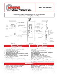
to the input block marked “Neutral” and connect the ground wire to the compression lug next to<br />
the input terminal block. For 3-wire input: connect each hot wire to each of the input block<br />
positions marked “Line”, connect the common wire to the input block marked “Neutral” and the<br />
ground wire to the compression lug next to the input terminal block. For 4-wire input: connect<br />
each hot wire to each of the input blocks marked “Line”. Phasing must be clockwise rotation –<br />
i.e. Phase B lags Phase A, connect the common wire to the input block marked “Neutral” and<br />
ground wire to the compression lug next to the input terminal block.<br />
INSTALLING AC OUTPUT WIRES:<br />
12. Connecting load wires without system distribution circuit breakers – connect load wires to the<br />
system’s terminal block labeled “OUTPUT”. Connect hot wire(s) to the output block marked<br />
“Nor. On”, the common wire(s) to the output block marked “Neutral” and the ground wire(s) to<br />
the compression lug next to the output terminal block. Emergency only load hot wires must be<br />
connected to the optional circuit on the output terminal block labeled “Nor. Off”.<br />
Connecting load wires with system distribution circuit breakers – connect the hot wire from each<br />
branch circuit to a circuit breaker and connect the common wire from each branch circuit to the<br />
neutral connection bar.<br />
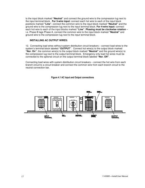
Figure 4.1 AC Input and Output connections<br />
17<br />
114306E—Install/User <strong>Manual</strong>