MODEL 5128/29 - Silent Knight
MODEL 5128/29 - Silent Knight
MODEL 5128/29 - Silent Knight

Create successful ePaper yourself
Turn your PDF publications into a flip-book with our unique Google optimized e-Paper software.
<strong>MODEL</strong> <strong>5128</strong>/<strong>29</strong><br />
Fire Slave Communicator<br />
Installation Manual<br />
Part Number 150805 Rev E<br />
11/06
Contents<br />
Section 1<br />
Introduction .........................................................................................................................................................1<br />
1.1 Features ...............................................................................................................................................................1<br />
1.2 Optional Devices .................................................................................................................................................2<br />
1.3 UL Fire Listed Receivers Compatible with the <strong>5128</strong>/<strong>29</strong> ....................................................................................2<br />
1.4 How to Use this Manual ......................................................................................................................................2<br />
1.5 How to Contact <strong>Silent</strong> <strong>Knight</strong> .............................................................................................................................3<br />
Section 2<br />
Agency Requirements ..........................................................................................................................3<br />
2.1 Telephone Requirements .....................................................................................................................................3<br />
2.2 FCC Warning ......................................................................................................................................................4<br />
2.3 UL Listings and Requirements ...........................................................................................................................4<br />
Section 3<br />
Panel Description and Installation .......................................................................................5<br />
3.1 Panel Description ................................................................................................................................................5<br />
3.1.1 Phone Line Monitors ....................................................................................................................................5<br />
3.1.2 Watchdog Circuit..........................................................................................................................................5<br />
3.1.3 Power Loss Reporting...................................................................................................................................5<br />
3.1.4 EEPROM ......................................................................................................................................................5<br />
3.1.5 DC Power......................................................................................................................................................6<br />
3.1.6 Indicator Lights.............................................................................................................................................6<br />
3.2 Environmental .....................................................................................................................................................7<br />
3.3 Wiring .................................................................................................................................................................7<br />
3.3.1 Wiring Precautions .......................................................................................................................................7<br />
3.3.2 Connector Descriptions.................................................................................................................................7<br />
3.3.3 Earth Ground Impedance ..............................................................................................................................7<br />
3.3.4 Wiring and Board Layout Diagram ..............................................................................................................8<br />
3.3.5 Electrical Ratings..........................................................................................................................................8<br />
3.3.6 Wire Routing.................................................................................................................................................9<br />
3.4 DC Power Connection ......................................................................................................................................10<br />
3.5 Mounting and Grounding ..................................................................................................................................11<br />
3.5.1 Preventing Water Damage ..........................................................................................................................11<br />
3.5.2 Grounding the 51<strong>29</strong> Board .........................................................................................................................11<br />
150805 i
Model <strong>5128</strong>/<strong>29</strong> Fire Slave Communicator Installation Manual<br />
3.5.3 Grounding the 51<strong>29</strong> Cover..........................................................................................................................11<br />
3.6 Channel Operation and Wiring .........................................................................................................................12<br />
3.6.1 Dry Contact .................................................................................................................................................12<br />
3.6.2 Voltage Input (Active High) .......................................................................................................................12<br />
3.7 AC Monitoring ..................................................................................................................................................13<br />
3.7.1 Voltage Input—Active High.......................................................................................................................13<br />
3.7.2 Dry Contact .................................................................................................................................................13<br />
3.7.3 Monitor AC (Available with the Model 51<strong>29</strong> only) ...................................................................................14<br />
3.8 Relay Connection ..............................................................................................................................................15<br />
3.9 Telephone Line Connection ..............................................................................................................................16<br />
3.10 Remote Annunciator Installation ......................................................................................................................17<br />
3.10.1 Model 5230 Connection..............................................................................................................................17<br />
Section 4<br />
Normal Operation ......................................................................................................................................18<br />
4.1 5230 Operation ..................................................................................................................................................18<br />
4.1.1 Power LED Indicator ..................................................................................................................................18<br />
4.1.2 Buzzer .........................................................................................................................................................18<br />
4.1.3 5230 Key Functions ....................................................................................................................................19<br />
4.2 Operating Modes ...............................................................................................................................................19<br />
Section 5<br />
Programming ...................................................................................................................................................20<br />
5.1 UL 864 Programming Requirements ................................................................................................................20<br />
5.2 Programming with the 5230 Remote Annunciator ...........................................................................................21<br />
5.2.1 Special Characters for Dialing ....................................................................................................................22<br />
5.3 Programming with the 5541 Downloading Software ........................................................................................22<br />
5.4 Programming Options .......................................................................................................................................22<br />
Section 6<br />
Reporting ..............................................................................................................................................................30<br />
6.1 Reporting Codes ................................................................................................................................................31<br />
Section 7<br />
Troubleshooting ..........................................................................................................................................32<br />
7.1 System Messages ...............................................................................................................................................32<br />
7.2 Silencing Troubles .............................................................................................................................................32<br />
ii 150805
SECTION 1<br />
INTRODUCTION<br />
The <strong>Silent</strong> <strong>Knight</strong> Model <strong>5128</strong>/<strong>29</strong> is a low-cost slave communicator that meets the requirements for UL 864,<br />
NFPA 72 Fire Alarm Systems for Central Station Service and NFPA 72 Remote Supervising Station Fire<br />
Alarm Systems.<br />
1.1 Features<br />
• Compatibility with the Security Industry Association (SIA) reporting format and several other standard<br />
reporting formats.<br />
• Four channel (zone) inputs for system status reporting: fire alarm (channel or zone 1); system trouble–<br />
channel 2 (or zone 2); supervisory–channel 3 (or zone 3); and miscellaneous–channel 4 (or zone 4).<br />
• Optional two-number dialing with same or different account codes and reporting formats. Alarms,<br />
troubles, and tests can be programmed to be reported to either or both numbers.<br />
• Programmable as rotary-only or as Touch-Tone/rotary dialing.<br />
• Built-in dual phone line-seizure circuit.<br />
• Dual phone line monitor circuits.<br />
• Transient voltage protection of phone lines.<br />
• Built-in audible trouble buzzer.<br />
• One relay output, programmable for alarm, trouble conditions, or trouble excluding low AC.<br />
• Light-emitting diodes (LEDs), visible from front of enclosure, indicating: trouble condition (yellow);<br />
presence of DC power (green), phone line 1 trouble (red); and phone line 2 trouble (red).<br />
• Easy, English-language programming using Model 5230 Remote Annunciator.<br />
• Fuseless design, 24 VDC.<br />
• Electrically erasable read-only memory (EEPROM) for nonvolatile storage of all programmable option<br />
data. Eliminates the need to reprogram the communicator if power is lost.<br />
• Built-in watchdog circuit that monitors the operation of the <strong>5128</strong>/<strong>29</strong> and resets the communicator if a fault<br />
is detected.<br />
• Active high or contact closure input.<br />
• Model 51<strong>29</strong> can directly monitor control panel’s primary power.<br />
• Compatibility with many Underwriters Laboratories (UL) Fire Listed receivers. (See Section 1.3 for list.)<br />
• Model <strong>5128</strong> housed in 8-5/8" x 4" x 1-3/8" enclosure for mounting inside control panel.<br />
• Model 51<strong>29</strong> housed in a 10" x 10" metal enclosure.<br />
150805 1
Model <strong>5128</strong>/<strong>29</strong> Fire Slave Communicator Installation Manual<br />
1.2 Optional Devices<br />
The following accessories are available for use with the Model <strong>5128</strong>/<strong>29</strong>:<br />
• 5230 Remote Annunciator for programming, troubleshooting, and system operation. Only one model 5230<br />
can be used.<br />
• Cable for 5230, P/N 130<strong>29</strong>4.<br />
• 5541 Downloading Software for remote programming. (Must be Revision 3.7 or later.)<br />
• 5530 Modem. Required if the 5541 downloading software is used.<br />
1.3 UL Fire Listed Receivers Compatible with the <strong>5128</strong>/<strong>29</strong><br />
The following UL Listed receivers are compatible with the <strong>5128</strong>/<strong>29</strong>:<br />
RECEIVER<br />
<strong>Silent</strong> <strong>Knight</strong> Model 9000, 9500, or 9800<br />
Note: The Model 9000 receiver does not<br />
accept CID format.<br />
1.4 How to Use this Manual<br />
FORMATS<br />
BFSK14<br />
BFSK23<br />
SK 3/1<br />
SK 4+2<br />
SIA8<br />
SIA20<br />
Contact ID (CID)<br />
Osborn & Hoffman Quickalert SK 3/1<br />
SK 4+2<br />
SIA8<br />
SIA20<br />
BFSK14<br />
BFSK23<br />
Ademco 685 SK 3/1<br />
SK 4+2<br />
FBI CP220 SK 3/1<br />
SK 4+2<br />
Radionics D6500 BFSK 1400<br />
BFSK 2300<br />
This manual is intended for use with Revision P or higher of the <strong>5128</strong>/<strong>29</strong> printed circuit board. If you are<br />
installing or servicing a different revision level and do not have the correct manual, contact <strong>Silent</strong> <strong>Knight</strong> for<br />
the correct information.<br />
In this manual, a rectangle represents a key that you press if you are using the optional Model 5230 Remote<br />
Annunciator. For example, “Press ENTER ” means “Press the key.”<br />
2 150805
Agency Requirements<br />
1.5 How to Contact <strong>Silent</strong> <strong>Knight</strong><br />
For questions and problems with <strong>Silent</strong> <strong>Knight</strong> products, contact <strong>Silent</strong> <strong>Knight</strong> Technical Support at<br />
800-328-0103 (or 763-493-6455). To order parts, contact <strong>Silent</strong> <strong>Knight</strong> Sales at 800-446-6444<br />
(or 763-493-6435).<br />
SECTION 2<br />
AGENCY REQUIREMENTS<br />
2.1 Telephone Requirements<br />
1. If requested by the telephone company, the following information must be provided before connecting this<br />
device to the phone lines:<br />
A. Manufacturer: <strong>Silent</strong> <strong>Knight</strong><br />
B. Model Number: <strong>5128</strong>/<strong>29</strong><br />
C. FCC Registration Number: AC6USA-75160-AL-E<br />
Ringer equivalence: 0.1B<br />
D. Type of jack (to be installed by the telephone company): RJ31X<br />
2. This device may not be directly connected to coin telephone or party line services.<br />
3. This device cannot be adjusted or repaired in the field. In case of trouble with the device, notify the installing<br />
company or return:<br />
<strong>Silent</strong> <strong>Knight</strong><br />
7550 Meridian Circle<br />
Maple Grove, MN 55369<br />
763-493-6455<br />
800-328-0103<br />
4. If the Model <strong>5128</strong>/<strong>29</strong> causes harm to the telephone network, the telephone company will notify the user in<br />
advance that temporary discontinuance of service may be required. If advance notice is not practical, the<br />
telephone company will notify the user as soon as possible. The user has the right to file a complaint with<br />
the Federal Communications Commission if he or she believes it is necessary.<br />
5. The telephone company may make changes in its facilities, equipment, operations, or procedures that<br />
could affect the operation of the equipment. If this happens, the telephone company will provide advance<br />
notice so that you can make the necessary modifications to maintain uninterrupted service.<br />
150805 3
Model <strong>5128</strong>/<strong>29</strong> Fire Slave Communicator Installation Manual<br />
2.2 FCC Warning<br />
WARNING:<br />
This device has been verified to comply with FCC Rules Part 15. Operation is subject to the following conditions: (1) This device may<br />
not cause radio interference, and (2) This device must accept any interference received, including interference that may cause<br />
undesired operation.<br />
2.3 UL Listings and Requirements<br />
Model<br />
<strong>5128</strong><br />
51<strong>29</strong><br />
Listed As:<br />
Signaling device subassembly for use in Fire Alarm Systems for Central<br />
Station Service.<br />
Signaling device subassembly for use in Remote Supervising Fire Alarm<br />
Systems.<br />
Signaling device for use in Fire Alarm Systems for Central Station Service.<br />
Signaling device for use in Remote Supervising Fire Alarm Systems.<br />
All UL installations must comply with the requirements described below. Refer to the control unit’s installation<br />
manual for complete information.<br />
<strong>5128</strong> Requirements:<br />
The <strong>5128</strong> must be mounted within a UL listed compatible fire control panel.<br />
51<strong>29</strong> Requirements:<br />
The 51<strong>29</strong> and the UL listed compatible fire control must be installed in the same room. All wiring between the<br />
51<strong>29</strong> and the UL Listed compatible fire control panel must be enclosed in conduit. The 51<strong>29</strong> must be mounted<br />
within 20 feet of the fire control.<br />
Requirements for both <strong>5128</strong> and 51<strong>29</strong>:<br />
All electrical connections must comply with the ratings shown in section 3.3.5. In a remote signaling<br />
installation, the control unit, slave dialer, and receiver at the remote site must all be UL listed for remote<br />
signaling.<br />
Install in accordance with NFPA 70 and NFPA 72.<br />
4 150805
Panel Description and Installation<br />
SECTION 3<br />
PANEL DESCRIPTION AND INSTALLATION<br />
3.1 Panel Description<br />
3.1.1 Phone Line Monitors<br />
The <strong>5128</strong>/<strong>29</strong> dialer has two phone line monitor circuits, which detect phone line faults by monitoring their<br />
voltages. These circuits feature a 40 to 90 second delay before a line fault is reported as a trouble. When a fault<br />
is detected for longer than this amount of time, the audible trouble signal will sound, the message will be<br />
displayed on the 5230 annunciator liquid crystal display (LCD) (if used), and the trouble will be reported to the<br />
central station.<br />
Note: To comply with industry standards, this product is equipped with line seizure. This means that any time the system’s<br />
dialer needs to communicate with the central station, it will NOT be possible to use any telephones that are<br />
on the same line(s) as the fire system. Normally this condition will last less than one minute, but could last for as<br />
long as 15 minutes under adverse telephone circuit conditions.<br />
3.1.2 Watchdog Circuit<br />
If the <strong>5128</strong>/<strong>29</strong> stops running, the watchdog circuit automatically detects the problem and attempts to resume<br />
normal operation by resetting the communicator. Each time the watchdog circuit resets the system, it also<br />
sounds the trouble signal.<br />
3.1.3 Power Loss Reporting<br />
The <strong>5128</strong>/<strong>29</strong> will report low AC conditions. It can monitor a contact closure AC failure output. The 51<strong>29</strong> can<br />
also monitor the control panel’s main AC power input.<br />
The AC report delay time is programmable. See Section 5, Step 24.<br />
3.1.4 EEPROM<br />
CAUTION:<br />
To avoid the risk of electrical shock, make sure the main control power is OFF when wiring. DO NOT apply power until<br />
wiring is completed following the procedures described in this manual.<br />
The electrically erasable read-only memory (EEPROM) is used to store specific information such as system<br />
configuration, telephone numbers, reporting format, and account numbers. The EEPROM retains the<br />
programmed information even when all electrical power is removed. It can be programmed more than 1,000<br />
times without losing its ability to store information.<br />
150805 5
Model <strong>5128</strong>/<strong>29</strong> Fire Slave Communicator Installation Manual<br />
3.1.5 DC Power<br />
The <strong>5128</strong>/<strong>29</strong> operates on 18-40 VDC rectified power from the main fire control panel.<br />
3.1.6 Indicator Lights<br />
The <strong>5128</strong>/<strong>29</strong> has four LEDs to indicate status.<br />
TROUBLE LED (yellow)<br />
ON - A system trouble condition exists.<br />
OFF - No trouble condition exists.<br />
Flashing - Silenced Trouble<br />
DC POWER LED (green)<br />
ON - The panel is running on DC power.<br />
OFF - The panel has lost all power.<br />
Flashing - The panel is reporting.<br />
PHONE LINE 1 LED (red)<br />
ON - Phone line 1 has a trouble condition.<br />
OFF - Normal condition.<br />
Flashing - Communication Trouble (Failed to report using this Line)<br />
PHONE LINE 2 LED (red)<br />
ON - Phone line 2 has a trouble condition.<br />
OFF - Normal condition.<br />
Flashing - Communication Trouble (Failed to report using this Line)<br />
6 150805
Panel Description and Installation<br />
3.2 Environmental<br />
It is important to protect the Model <strong>5128</strong>/<strong>29</strong> from water. To prevent water damage, the following<br />
conditions should be AVOIDED when installing the units:<br />
• Intended for indoor use only.<br />
• Do not mount directly on exterior walls, especially masonry walls (condensation)<br />
• Do not mount directly on exterior walls below grade (condensation)<br />
• Protect from plumbing leaks<br />
• Protect from splash caused by sprinkler system inspection ports<br />
• Do not mount in areas with humidity-generating equipment (such as dryers, production<br />
machinery)<br />
When selecting a location to mount the Model <strong>5128</strong>/<strong>29</strong>, the unit should be mounted where it will<br />
NOT be exposed to temperatures outside the range of 0°C-49°C (32°F-120°F) or humidity outside<br />
the range of 10%-93% at 30°C (86°F) noncondensing.<br />
3.3 Wiring<br />
3.3.1 Wiring Precautions<br />
High and low voltage must be separated by at least one-quarter inch. See Section 3.3.6 for more information.<br />
High current input/output: AC monitoring (if monitored directly)<br />
Low current input/output: 24 VDC power and channel (zone) wiring<br />
Audio input/output: Telephone wiring<br />
High frequency noise, such as that produced by the inductive reactance of a bell, can also be reduced by<br />
running the wire through ferrite shield beads or by wrapping it around a ferrite toroid.<br />
3.3.2 Connector Descriptions<br />
PIN CONNECTOR<br />
P1<br />
P2<br />
P4<br />
P5<br />
FUNCTION<br />
DC power<br />
Channel (zone) inputs<br />
5230 connect<br />
Low AC channel input<br />
3.3.3 Earth Ground Impedance<br />
All circuits on this panel have an earth ground impedance of zero (0) Ohms.<br />
150805 7
Model <strong>5128</strong>/<strong>29</strong> Fire Slave Communicator Installation Manual<br />
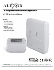
3.3.4 Wiring and Board Layout Diagram<br />
Earth Ground<br />
DC Power<br />
(See Section 3.4)<br />
Silence Button<br />
(See Section 7.2)<br />
5230 Connector<br />
(See Section 3.10.1)<br />
Channel Inputs<br />
(See Section 3.6)<br />
Low AC Channel<br />
(See Section 3.7)<br />
All Circuits Supervised<br />
Power Limited except<br />
Direct AC Monitoring,<br />
which is supervised only<br />
To Telco<br />
Lines (See<br />
Section 3.9)<br />
Relay Terminals<br />
Contact Rating<br />
1A @ 24VDC or 24VAC<br />
(See Section 3.8)<br />
Direct AC Monitoring<br />
(See Section 3.7.3)<br />
Figure 3-1 Model <strong>5128</strong>/<strong>29</strong> Wiring and Board Layout<br />
3.3.5 Electrical Ratings<br />
PRIMARY DC VDC: 18 - 40<br />
Current draw, standby at 24 VDC<br />
143 mA max. with annunciator attached<br />
84 mA max. without annunciator<br />
AC RATING<br />
CHANNEL (ZONE) INPUTS*<br />
Active High<br />
Dry Contacts<br />
MAX. WATCHDOG RESPONSE<br />
Current draw, alarm at 24 VDC<br />
227 mA max. with annunciator attached<br />
154 mA max. without annunciator<br />
120 VAC @ 60Hz, 45 mA max.<br />
18 - 30 VDC input<br />
15 mA max. current draw<br />
4.7 VDC, 6 mA max.<br />
50 seconds<br />
* Supervised for opens only. No ground fault detection is provided.<br />
8 150805
Panel Description and Installation<br />
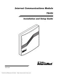
3.3.6 Wire Routing<br />
High voltage and low voltage inputs must be separated by at least one-quarter inch and must be wired through<br />
different knockout holes in the fire control cabinet to maintain the separation.<br />
Figure 3-2 below shows an example of how to route the wire if you are using the model 51<strong>29</strong>. If you are using<br />
the <strong>5128</strong>, refer to the fire control panel installation manual for wire routing instructions.<br />
Cable Clamp<br />
See instructions<br />
Below<br />
Board Ground<br />
To Telco<br />
Lines<br />
Cable Tie<br />
Must be enclosed<br />
in conduit.<br />
From AC<br />
Figure 3-2 Routing Wire for the 51<strong>29</strong><br />
150805 9
Model <strong>5128</strong>/<strong>29</strong> Fire Slave Communicator Installation Manual<br />
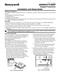
3.4 DC Power Connection<br />
Connect DC power to the <strong>5128</strong>/<strong>29</strong> as shown in Figure 3-3.<br />
Supervised<br />
Red<br />
Black<br />
Positive<br />
Power from<br />
Control Panel<br />
Negative<br />
Power from<br />
Control Panel<br />
18-40 VDC rectified power<br />
(See Figure 3-2 for cable<br />
clamp installation)<br />
Figure 3-3 DC Power Connections<br />
10 150805
Panel Description and Installation<br />
3.5 Mounting and Grounding<br />
The 51<strong>29</strong> cabinet should be installed in the same room as the control panel (wire in conduit). Mount the 51<strong>29</strong><br />
so it is firmly secured to the wall surface. When mounting on concrete, especially when moisture is expected,<br />
attach a piece of ¾” plywood to the concrete surface before attaching the 51<strong>29</strong>.<br />
3.5.1 Preventing Water Damage<br />
Water damage to the fire system can be caused by moisture entering the cabinet through the conduits. Conduits<br />
that are installed to enter the top of the cabinet are most likely to cause water problems. Installers should take<br />
reasonable precautions to prevent water from entering the cabinet. Water damage is not covered under<br />
warranty.<br />
If you are using the <strong>5128</strong>, refer to the fire control panel installation manual for mounting instructions.<br />
3.5.2 Grounding the 51<strong>29</strong> Board<br />
Ground the 51<strong>29</strong> board as shown in Figure 3-2.<br />
3.5.3 Grounding the 51<strong>29</strong> Cover<br />
Before connecting power to the 51<strong>29</strong>, connect the earth ground wire to the base and cover. Make sure that the<br />
ring lugs are oriented properly. Figure 3-4 shows the proper connection and orientation.<br />
After the 51<strong>29</strong>’s cover and base are attached, make a slight bend to the wire that is attached to the cover. This<br />
keeps the wire from getting caught between the cover and base when the cover is closed.<br />
Figure 3-4 Connecting the Ground Wire<br />
150805 11
Model <strong>5128</strong>/<strong>29</strong> Fire Slave Communicator Installation Manual<br />
3.6 Channel Operation and Wiring<br />
The <strong>5128</strong>/<strong>29</strong> features four fully supervised channel (zone) inputs. They can be programmed to accept two types<br />
of inputs. Contact closure, and active high voltage input.<br />
CHANNEL 1 (ZONE 1): FIRE ALARM<br />
CHANNEL 2 (ZONE 2): FIRE TROUBLE<br />
CHANNEL 3 (ZONE 3): SPRINKLER SUPERVISORY<br />
CHANNEL 4 (ZONE 4): FIRE ALARM<br />
3.6.1 Dry Contact<br />
A short across the end-of-line resistor (EOL) causes an active channel (zone). An open loop causes a trouble<br />
condition.See Figure 3-5.<br />
3.6.2 Voltage Input (Active High)<br />
Figure 3-5 illustrates how to wire the <strong>5128</strong>/<strong>29</strong> for an active high voltage input. The input must be from a<br />
compatible UL listed control panel. A short across the EOL or an open loop causes a trouble condition. Pulling<br />
the input high (18 to 30 VDC) causes the channel to activate.<br />
Dry Contact<br />
Example<br />
UL Listed 4.7 k EOL<br />
Model 7628<br />
Voltage Input<br />
Example<br />
Supervised<br />
Power Limited<br />
Figure 3-5 P2 Connections<br />
12 150805
Panel Description and Installation<br />
3.7 AC Monitoring<br />
The <strong>5128</strong>/<strong>29</strong> features an AC monitoring circuit. The communicator will report AC trouble when AC has been<br />
below 85 percent of nominal for a programmed amount of time. The <strong>5128</strong> AC monitoring can be performed<br />
with a dry contact active high voltage input (see Section 3.7.1). The Model 51<strong>29</strong> can monitor AC voltage<br />
directly (see Section 3.7.3).<br />
3.7.1 Voltage Input—Active High<br />
If the fire control panel has an active high AC trouble voltage output (18 to 30 VDC), attach this output directly<br />
to the low AC channel input on the <strong>5128</strong>/<strong>29</strong>. (See Figure 3-6.)<br />
3.7.2 Dry Contact<br />
If the fire control panel monitors its AC input and has a contact closure AC trouble output, connect the AC<br />
monitor input of the <strong>5128</strong>/<strong>29</strong> through the normally open contacts of the FACP (see Figure 3-6). Select “Active<br />
Low” in programming Step 23.<br />
Supervised<br />
Power Limited<br />
Supervised<br />
Power Limited<br />
Active High Input Configuration<br />
Dry Contact Input Configuration<br />
Figure 3-6 AC Monitoring Configurations Through P5<br />
150805 13
Model <strong>5128</strong>/<strong>29</strong> Fire Slave Communicator Installation Manual<br />
3.7.3 Monitor AC (Available with the Model 51<strong>29</strong> only)<br />
The <strong>5128</strong>/<strong>29</strong> can perform direct AC monitoring of the fire control panel’s 120 VAC power input. The wires<br />
attached to the 51<strong>29</strong> board can be connected directly to the AC as shown in Figure 3-7 below. Make sure you<br />
do not attach the low AC channel input here.<br />
Supervised<br />
Connections must be made<br />
in a separate electrical box<br />
Figure 3-7 Direct AC Input<br />
Note:<br />
Refer to installation instructions for the fire alarm control panel to determine this interface is compatible with the<br />
unit.<br />
14 150805
Panel Description and Installation<br />
3.8 Relay Connection<br />
The <strong>5128</strong>/<strong>29</strong> provides one relay output. You can connect the relay in normally open or normally closed<br />
configurations or both. The relay contacts are rated at 1 A, 24 VDC/24 VAC. See Figure 3-8 for relay contact<br />
connections.<br />
The relay can be used for either of the following:<br />
• To activate for any alarm.<br />
• To activate for system trouble conditions, loss of AC power, failure of the <strong>5128</strong>/<strong>29</strong> to communicate, and<br />
phone line troubles.<br />
• To activate for system trouble conditions and failure of the <strong>5128</strong>/<strong>29</strong> to communicate, and phone line<br />
troubles.<br />
Programmable<br />
Relay<br />
1A 24 VDC/24 VAC Resistive<br />
14 – 22 AWG Wire<br />
Figure 3-8 Relay Connection<br />
150805 15
Model <strong>5128</strong>/<strong>29</strong> Fire Slave Communicator Installation Manual<br />
3.9 Telephone Line Connection<br />
To meet requirements for NFPA 72 Fire Alarm Systems for Central Station Service or NFPA 72 Remote<br />
Supervising Station Fire Alarm Systems, both telephone lines must be installed. Connect the <strong>5128</strong>/<strong>29</strong> to the<br />
phone lines using RJ31X type phone jacks as shown in Figure 3-9. The telephone company will install RJ31X<br />
jacks upon request.<br />
Figure 3-9 Telephone Wiring<br />
16 150805
Panel Description and Installation<br />
3.10 Remote Annunciator Installation<br />
The optional Model 5230 Remote Annunciator can be connected to the <strong>5128</strong>/<strong>29</strong> for system operation,<br />
programming, and troubleshooting. Note that only one 5230 can be used. If the 5230 is used, a cable, part<br />
number 130<strong>29</strong>4 (ordered separately) is also needed.<br />
Model 5230 key functions are described in Section 4.1.3; programming instructions are in Section 5.<br />
3.10.1 Model 5230 Connection<br />
The table below shows how to make the connections. Figure 3-10 below shows the location of the 5230<br />
terminal block.<br />
5230 TERMINALS<br />
CABLE WIRE COLORS<br />
(P/N 130<strong>29</strong>4)<br />
1 GROUND BROWN<br />
2 POWER RED<br />
3 OUTPUT ORANGE<br />
4 INPUT YELLOW<br />
To <strong>5128</strong>/<strong>29</strong><br />
P4 Connector<br />
(See Section 3.3.2)<br />
Wire colors shown are<br />
for cable P/N 130<strong>29</strong>4<br />
Figure 3-10 Model 5230 Back View<br />
150805 17
Model <strong>5128</strong>/<strong>29</strong> Fire Slave Communicator Installation Manual<br />
SECTION 4<br />
NORMAL OPERATION<br />
This section describes normal system operations using the 5230 remote annunciator.<br />
4.1 5230 Operation<br />
The 5230 is equipped with an LCD (liquid crystal display) that displays English-language messages. If the<br />
<strong>5128</strong>/<strong>29</strong> is not being programmed, the LCD cycles through all messages that are applicable at the time,<br />
showing a different one every 1.5 seconds. The messages are listed in the troubleshooting section of this<br />
manual (Section 7.2).<br />
For programming and troublshooting only.<br />
Do not leave on the system.<br />
Figure 4-1 Model 5230 Remote Annunciator (Front)<br />
4.1.1 Power LED Indicator<br />
When DC power is being supplied, the POWER LED glows steadily. If DC power is not being supplied, the<br />
POWER LED is off.<br />
4.1.2 Buzzer<br />
An audio transducer buzzer is built into the 5230 annunciator. It produces short beeps to annunciate keystrokes.<br />
It also emits a long, high-pitched tone to indicate a trouble condition or when an annunciator function has been<br />
entered incorrectly.<br />
18 150805
Normal Operation<br />
4.1.3 5230 Key Functions<br />
The 5230 annunciator function keys are described below. Keys not described here are used only for entering<br />
digits.<br />
Note: The message “TRY AGAIN” appears if you do not press any keys for five seconds while accessing a function or<br />
if you attempt to access a function before exiting from another function.<br />
Table 4-1: Key Functions<br />
CLEAR<br />
FUNCTION NAME EXPLANATION KEYSTROKES<br />
SYSTEM TEST<br />
RESET DIALER<br />
4.2 Operating Modes<br />
Corrects mistakes. If you enter a function<br />
incorrectly, the 5230 will emit a long, highpitched<br />
tone.<br />
Tests the communicator by sending a test<br />
report to the central station.<br />
Aborts an in-progress call to the central<br />
station.<br />
0 ENTER [Installer’s or Operator’s Code]<br />
3 ENTER [Installer’s Code]<br />
BEGIN DOWNLOAD Begin downloading session. 4 ENTER [Installer’s Code]<br />
ENTER PROGRAMMING<br />
MODE<br />
SET TIME<br />
Enters programming mode where you<br />
change programmable options.<br />
CLEAR<br />
2 7 ENTER [Installer’s Code]<br />
To exit programming mode, press<br />
STEP STEP CLEAR CLEAR<br />
To set the time:<br />
1. Press 9 ENTER<br />
2. Enter Installer’s or Operator’s Code. The SET MODE LED will turn on.<br />
3. Enter the time in 24-hour military format (include leading zeros).<br />
EXAMPLE:<br />
To enter SET TIME mode and set the time for 3:30 PM, the keystrokes are:<br />
9 ENTER [Code] 1 5 3 0 ENTER .<br />
OPERATING MODE: ALLOWED DURING ALARM: CODE REQUIRED:<br />
0 System test NO Installer’s or Operator’s<br />
3 Dialer reset YES Installer’s<br />
4 Download NO Installer’s<br />
9 Set time NO Installer’s or Operator’s<br />
27 Program NO Installer’s<br />
150805 19
Model <strong>5128</strong>/<strong>29</strong> Fire Slave Communicator Installation Manual<br />
SECTION 5<br />
PROGRAMMING<br />
The Model <strong>5128</strong>/<strong>29</strong> provides a wide variety of features that can be selected for use depending on your needs.<br />
These features are stored in an EEPROM (Electrically Erasable Programmable Read-Only Memory) chip<br />
which has been factory-programmed. Section 5.1 describes how to change programming options using the<br />
5230 Remote Annunciator. The 5230 Remote Annunciator is required for all programming changes. Section<br />
5.2 explains using the Model 5541 Downloading Software for programming. All programmable options are<br />
described in Section 5.3.<br />
5.1 UL 864 Programming Requirements<br />
NOTICE TO USERS, INSTALLERS, AUTHORITIES HAVING<br />
JURISDICTION, AND OTHER INVOLVED PARTIES: This product<br />
incorporates field programmable software. In order for the product to comply<br />
with the requirements in the Standard for Control Units and Accessories for<br />
Fire Alarm Systems, UL 864, certain programming features or options must be<br />
limited to specific values or not used at all as indicated below.<br />
Programming Option<br />
Permitted in<br />
UL 864 (Y/N)<br />
Possible<br />
Settings<br />
Settings Permitted in<br />
UL 864<br />
AC Loss Hours Y 0 – 15 hours 1 – 3 hours<br />
Zone Supervised Y Y/N Y<br />
Formats Y 0–8 0, 5 or 8<br />
Zone Response Y 0–3 0 or 1<br />
Relay #1 Y 0–2 0 or 1<br />
20 150805
Programming<br />
5.2 Programming with the 5230 Remote Annunciator<br />
Note:<br />
The system will automatically time out of programming mode if no keys are pressed for four minutes. If you press<br />
function keys very quickly, you may get ahead of the LCD display. Wait for the appropriate message to be displayed<br />
before you press ENTER .<br />
TO:<br />
KEYSTROKES:<br />
ENTER PROGRAMMING MODE 2 7 ENTER [Installer’s Code]<br />
The first line of the LCD will show the programming option for<br />
Step 1, “ZONE ACTIVE.” The second line will show the most recently programmed<br />
value for that option.<br />
PROGRAM AN OPTION Type in your new data and then press ENTER .<br />
SKIP A STEP Press ENTER .<br />
The data in the skipped step will not change. The LCD will show the next option.<br />
GO TO A SPECIFIC STEP Press STEP . The first line of the LCD will show “ENTER THE STEP #” and the<br />
current step number. Type in the new step number, then press ENTER . Line 1 of<br />
the LCD will show the option name; line 2 will show the programmed data for the<br />
step. (If you try to go to a step that does not exist, the display will go back to the<br />
previous step.)<br />
SELECT YES OR NO<br />
Press any digit to toggle Yes and No.<br />
SELECT AN OPTION FROM A MENU Press the option number. (Option numbers appear next to the option name in Section<br />
5.3.)<br />
ENTER ALPHABETIC DATA OR<br />
NUMBERS LARGER THAN 9<br />
SHIFT 1<br />
SHIFT 2<br />
SHIFT 3<br />
SHIFT 4<br />
SHIFT 5<br />
for A or 10<br />
for B or 11<br />
for C or 12<br />
for D or 13<br />
for E or 14<br />
Note that only the alphabetic characters appear on the display.<br />
CORRECT AN ERROR<br />
Press CLEAR . Then type in the correct data and press ENTER .<br />
(If you have not pressed the ENTER key.)<br />
LEAVE PROGRAMMING MODE Press STEP STEP CLEAR CLEAR .<br />
AT ANY TIME<br />
150805 21
Model <strong>5128</strong>/<strong>29</strong> Fire Slave Communicator Installation Manual<br />
5.2.1 Special Characters for Dialing<br />
Use Table 5-1 to determine which special characters to use when setting the Line Prefix options during<br />
programming.<br />
Table 5-1: Special Characters<br />
To Enter: Press LCD Display<br />
Pause 1<br />
A<br />
* 2<br />
B<br />
# 3<br />
C<br />
2nd Dial Tone 4<br />
D<br />
5.3 Programming with the 5541 Downloading Software<br />
The Model 5541 Remote Downloading Software can be used to program the <strong>5128</strong>/<strong>29</strong> from a remote site. Note<br />
that Revision 3.7 or later of the software is required. The Model 5530 Modem must also be connected to the<br />
computer that runs the software.<br />
The downloading software is organized into menus. As you move through the software menus, the screens tell<br />
you how to select options. The programming form in Section 5.4 lists the options by step number, that is, in the<br />
order they appear if you use the 5230 to program. The form also tells you which 5541 software menu the<br />
option appears on. (See Figure 5-1 for an example.)<br />
Refer to the manuals that accompany the downloading software and modem for information about how to set<br />
up and run the software and modem.<br />
5.4 Programming Options<br />
This section of the manual describes the programming options. Figure 5-1 shows how you can use the programming<br />
form, which begins on the next page, to keep a record of how you have programmed an installation<br />
by checking off or writing in your choices in Column 4 of the chart. The factory-programmed defaults also<br />
appear in Column 4. This form is perforated for your convenience.<br />
Figure 5-1 Using the Programming Form<br />
22 150805
Programming<br />
Table 5-2: Programming Form<br />
Step # /<br />
From<br />
Menu<br />
Option<br />
Description<br />
Your Choice<br />
(D) = Default<br />
1<br />
System<br />
Menu<br />
ZONE ACTIVATION<br />
Select input type.<br />
0 = Dry contact input<br />
1 = Active high input<br />
2 = Currently not available. Do not select.<br />
Dry contact (D)<br />
Active high<br />
2<br />
System<br />
Menu<br />
ZONE SUPERVISED<br />
Yes = All zones supervised<br />
No = All zones unsupervised<br />
Yes (D)<br />
No<br />
3<br />
System<br />
Menu<br />
LATCH SPRINKLER<br />
Yes = When the sprinkler zone shorts for a duration longer than the Zone<br />
Response (set in steps 8 through 11), the annunciator remains active until<br />
reported or manually silenced.<br />
Yes (D)<br />
No<br />
No = When the sprinkler zone shorts for a duration longer than the Zone<br />
Response (set in steps 8 through 11), the zone will follow system status<br />
and indicate a supervisory on that zone for the duration of the faulted<br />
condition.<br />
4<br />
System<br />
Menu<br />
CHANNEL #1 TYPE<br />
Alarm input<br />
0 = Fire<br />
1 = Sprinkler<br />
Fire (D)<br />
Sprinkler<br />
5<br />
System<br />
Menu<br />
CHANNEL #2 TYPE<br />
Trouble input<br />
0 = Fire<br />
1 = Sprinkler<br />
Fire (D)<br />
Sprinkler<br />
6<br />
System<br />
Menu<br />
CHANNEL #3 TYPE<br />
Supervisory input<br />
0 = Fire<br />
1 = Sprinkler<br />
Fire<br />
Sprinkler (D)<br />
7<br />
System<br />
Menu<br />
CHANNEL #4 TYPE<br />
Alarm input<br />
0 = Fire<br />
1 = Sprinkler<br />
2 = Undefined: For other fire related signalling.<br />
Fire (D)<br />
Sprinkler<br />
Undefined<br />
150805 23
Model <strong>5128</strong>/<strong>29</strong> Fire Slave Communicator Installation Manual<br />
Table 5-2: Programming Form<br />
Step # /<br />
From<br />
Menu<br />
Option<br />
Description<br />
Your Choice<br />
(D) = Default<br />
NOTES FOR STEPS 8-11:<br />
Channel response time speeds are not intended to be used as a smoke verification feature. Possible choices for channel response times are<br />
0-3 (described below).<br />
8<br />
System<br />
Menu<br />
ZONE RESPONSE #1 0 = 0.3 to 0.4 seconds 1 = 3 to 4 seconds<br />
2 = 15 to 20 seconds 3 = 30 to 40 seconds<br />
NOTE: If you make a mistake and program a number other than 0-3, the<br />
resulting zone speed will be:<br />
4 = 0.3 to 0.4 seconds 5 = 3 to 4 seconds<br />
6 = 15 to 20 seconds 7 = 30 to 40 seconds<br />
8 = 0.3 to 0.4 seconds<br />
9 = 3 to 4 seconds<br />
0.3 to 0.4 sec (D)<br />
3 to 4 sec<br />
15 to 20 sec<br />
30 to 40 sec<br />
9<br />
System<br />
Menu<br />
10<br />
System<br />
Menu<br />
11<br />
System<br />
Menu<br />
12<br />
System<br />
Menu<br />
13<br />
System<br />
Menu<br />
14<br />
Dialer<br />
Menu<br />
15<br />
Dialer<br />
Menu<br />
ZONE RESPONSE #2 Factory programmed as “1” (3 to 4 seconds). Cannot be changed. No selection.<br />
ZONE RESPONSE #3 (See step 8.) 0.3 to 0.4 sec (D)<br />
3 to 4 sec<br />
15 to 20 sec<br />
30 to 40 sec<br />
ZONE RESPONSE #4 (See step 8.) 0.3 to 0.4 sec (D)<br />
3 to 4 sec<br />
15 to 20 sec<br />
30 to 40 sec<br />
RELAY #1<br />
INSTALLER’S CODE<br />
OPERATOR’S CODE<br />
DIALER TYPE<br />
0 = Relay activates on alarm<br />
1 = Relay activates on system trouble<br />
2 = Relay activates on system trouble excluding Low AC<br />
Installer’s code [4 digits]. For programming and other system control<br />
functions. Can also perform all the same operations as the operator’s code.<br />
(See Section 4.2 for specific information about which functions the code<br />
can perform.)<br />
Operator’s code [4 digits]. Used for basic operation. (See Section 4.2 for<br />
specific information about which functions the code can perform.) This<br />
code must be different from the installer’s code.<br />
0 = USA<br />
1 = 9000 Direct (Do not use this option.)<br />
2 = European (used for Europe and Asia)<br />
Alarm<br />
Trouble<br />
Trouble excluding<br />
low AC (D)<br />
________________<br />
Default = <strong>5128</strong><br />
________________<br />
Default = 1111<br />
USA (D)<br />
European<br />
24 150805
Programming<br />
Table 5-2: Programming Form<br />
Step # /<br />
From<br />
Menu<br />
Option<br />
Description<br />
Your Choice<br />
(D) = Default<br />
16<br />
Dialer<br />
Menu<br />
17<br />
Dialer<br />
Menu<br />
18<br />
Dialer<br />
Menu<br />
19<br />
Dialer<br />
Menu<br />
20<br />
Dialer<br />
Menu<br />
21<br />
Dialer<br />
Menu<br />
22<br />
Dialer<br />
Menu<br />
23<br />
Dialer<br />
Menu<br />
COMPUTER ENABLE<br />
TOUCHTONE # 1<br />
LINE 1 PREFIX<br />
TOUCHTONE # 2<br />
LINE 2 PREFIX<br />
Yes = Downloading computer used.<br />
No = Downloading computer NOT used.<br />
Yes = Phone #1 will try both TouchTone and rotary.<br />
No = Phone #1 will use rotary dialing only.<br />
Up to eight digits. See section 5.2.1 for information on using special<br />
characters for pauses, *, etc.<br />
Yes = Phone #2 will try both TouchTone and rotary.<br />
No = Phone #2 will use rotary dialing only.<br />
Up to eight digits. See section 5.2.1 for information on using special<br />
characters for pauses, *, etc.<br />
MUST REPORT #1 Yes = Reports must always be sent to central station phone #1.<br />
No = If another phone number is available first, no report to phone #1.<br />
Note: If must report is selected for #1 or #2 then the event will report to<br />
that account.<br />
MUST REPORT #2 Yes = Reports must always be sent to central station phone #2.<br />
No = If another phone number is available first, no report to phone #1.<br />
Note: If must report is selected for #1 or #2 then the event will report to<br />
that account.<br />
AC ACTIVATION<br />
0 = Active high<br />
1 = Active low<br />
2 = AC Monitored<br />
Yes (D)<br />
No<br />
Yes<br />
No (D)<br />
________________<br />
Default = None<br />
Yes<br />
No (D)<br />
________________<br />
Default = None<br />
Yes (D)<br />
No<br />
Yes (D)<br />
No<br />
Active high<br />
Active low<br />
Monitor AC (D)<br />
150805 25
Model <strong>5128</strong>/<strong>29</strong> Fire Slave Communicator Installation Manual<br />
Table 5-2: Programming Form<br />
Step # /<br />
From<br />
Menu<br />
Option<br />
Description<br />
Your Choice<br />
(D) = Default<br />
24<br />
Dialer<br />
Menu<br />
25<br />
Dialer<br />
Menu<br />
AC LOSS HOURS Enter the number of hours before AC power loss is reported. Set to 0-15<br />
hours for NFPA 72 Fire Alarm Systems for Central Station Service<br />
(Chapter 4-3). Set to 15 hours for NFPA 72 Remote Supervising Station<br />
Fire Alarm Systems. Set to 0 if you are using a fire control panel that has a<br />
built-in delay. (Refer to the panel manual for details.)<br />
To program a number larger than 9, use:<br />
SHIFT 1 for 10<br />
SHIFT 2 for 11<br />
SHIFT 3 for 12<br />
SHIFT 4 for 13<br />
SHIFT 5 for 14<br />
SHIFT 6 for 15<br />
Note: For all UL installations AC power loss report needs to be set from<br />
1–3 hours.<br />
# RINGS Enter the number of rings before<strong>5128</strong>/<strong>29</strong> answers a downloading call.<br />
Options are 2-14, minimum is 2. Enter “0” to disable ring detector.<br />
_______<br />
Default = 2<br />
____<br />
Default = 10<br />
NOTES FOR STEPS 26 THROUGH 30.<br />
Steps 26-30 apply only if the 3/1 format is selected. The 3/1 format is an old format that does not make full use of <strong>5128</strong>/<strong>29</strong> reporting<br />
capabilities. The 3/1 format sends only one digit or letter for an event. It does not send the zone number with the event. Use this format<br />
only if required by the receiver.<br />
If you are using the 3/1 reporting format, use Steps 26-30 to select the digit (0-9) that will be sent for each event.<br />
The letters A through E can be used if the receiver can accept them. Use SHIFT 1 for A, SHIFT 2 for B and so on.<br />
Do not duplicate any digits or letters. For example, do not use “0” for both alarm code (in Step 26) and trouble code (in Step 28). Note<br />
that the 3/1 format does not distinguish between “0” and “A”, so do not use “0” if you’re using “A” and vice versa.<br />
See Section 6 for more information about the 3/1 format.<br />
26<br />
Dialer<br />
3/1 ALARM CODE Select the digit that will be transmitted to the central station for an alarm.<br />
(See “NOTES” above if you need more information.)<br />
____<br />
Default = 1<br />
Menu<br />
27 3/1 SPKLR CODE 3/1 code for sprinkler supervisory conditions.<br />
____<br />
Dialer<br />
Menu<br />
28<br />
Dialer<br />
Menu<br />
(Feature available with<br />
Revision H or later<br />
boards.)<br />
(See “NOTES” above if you need more information.)<br />
3/1 TROUBLE CODE 3/1 code for trouble conditions.<br />
(See “NOTES” above if you need more information.)<br />
Default = 2<br />
____<br />
Default = 8<br />
26 150805
Programming<br />
Table 5-2: Programming Form<br />
Step # /<br />
From<br />
Menu<br />
Option<br />
Description<br />
Your Choice<br />
(D) = Default<br />
<strong>29</strong><br />
Dialer<br />
Menu<br />
30<br />
Dialer<br />
Menu<br />
31<br />
Dialer<br />
Menu<br />
32<br />
Dialer<br />
Menu<br />
33<br />
Dialer<br />
Menu<br />
3/1 RESTORE CODE 3/1 code for restorals of alarm or trouble conditions.<br />
(See “NOTES” above if you need more information.)<br />
3/1 TEST CODE 3/1 code for reporting tests.<br />
(See “NOTES” above if you need more information.)<br />
ALARM #1 1ST Yes = Report alarms to central station phone #1 first.<br />
No = Report alarms to central station phone #2 first.*<br />
TROUBLE #1 1ST Yes = Report troubles to central station phone #1 first.<br />
No = Report troubles to central station phone #2 first.*<br />
TEST #1 1ST Yes = Report tests to central station phone #1 first.<br />
No = Report tests to central station phone #2 first.*<br />
____<br />
Default = 7<br />
____<br />
Default = 9<br />
Yes (D)<br />
No<br />
Yes (D)<br />
No<br />
Yes (D)<br />
No<br />
* Only if Must Report #1 (Step 21) is selected as “No”. If Step 21 is selected as “Yes” and report is complete to account #1, the<br />
no attempt is to account #2<br />
34<br />
Dialer<br />
ACCOUNT #1 Account # for central station phone #1 (6 digits; leading zeros if shorter). ________________<br />
Default = 10<strong>5128</strong><br />
Menu<br />
35<br />
Dialer<br />
ATTEMPTS #1 Number of times phone line #1 will try to dial each central station acct. #<br />
before “DIALER FAILED” displays on the 5230 LCD. Range is 3 to 5.<br />
____<br />
Default = 3<br />
Menu<br />
36<br />
Dialer<br />
Menu<br />
FORMAT #1 Select reporting format for phone line #1.<br />
See Section 6 for descriptions of these formats.<br />
0 = SIA8<br />
1 = Reserved<br />
2 = SK4+2<br />
3 = BFSK14<br />
4 = BFSK23<br />
5 = SIA20<br />
6 = 3/1 14<br />
7 = 3/1 23<br />
8 = Contact ID<br />
SIA8<br />
Reserved<br />
SK4+2<br />
BFSK14<br />
BFSK23<br />
SIA20 (D)<br />
3/1 14<br />
3/1 23<br />
CID<br />
150805 27
Model <strong>5128</strong>/<strong>29</strong> Fire Slave Communicator Installation Manual<br />
Table 5-2: Programming Form<br />
Step # /<br />
From<br />
Menu<br />
Option<br />
Description<br />
Your Choice<br />
(D) = Default<br />
37<br />
Dialer<br />
Menu<br />
38<br />
Dialer<br />
Menu<br />
39<br />
Dialer<br />
Menu<br />
40<br />
Dialer<br />
Menu<br />
41<br />
Dialer<br />
Menu<br />
42<br />
Dialer<br />
Menu<br />
43<br />
Dialer<br />
Menu<br />
CIC #1<br />
PHONE #1<br />
ACCOUNT #2<br />
Carrier Identification Code is the prefix that needs to be dialed before a<br />
phone number to access a particular long distance carrier. Use special<br />
characters to add pauses, #, *, and "look for second dial tone" characters<br />
into the phone number. See STEP 38 for list of special characters.<br />
Enter the phone number for phone line #1 (up to 16 digits). The<br />
following special options and characters can be part of a phone<br />
number: pause; look for second dial tone; * (asterisk); and #<br />
(number or pound symbol). For “pause”, press SHIFT 1 . (“A”<br />
displays on LCD.) For “*”, press SHIFT 2 . (“B” displays on the<br />
LCD.) For “#”, press SHIFT 3 . (“C” displays on LCD.) For “look<br />
for second dial tone”, press SHIFT 4 . (“D” displays on LCD.)<br />
Account number for central station phone #2 (6 digits; leading zeros if<br />
shorter).<br />
ATTEMPTS #2 Number of times phone line #2 will try to dial each central station acct. #<br />
before “DIALER FAILED” displays on the 5230 LCD. Range is 3 to 5.<br />
FORMAT #2 Select reporting format for phone line #2.<br />
See Section 6 for descriptions of these formats.<br />
0 = SIA8<br />
1 = Reserved<br />
2 = SK4+2<br />
3 = BFSK14<br />
4 = BFSK23<br />
5 = SIA20<br />
6 = 3/1 14<br />
7 = 3/1 23<br />
8 = Contact ID<br />
CIC #2<br />
PHONE #2<br />
Carrier Identification Code is the prefix that needs to be dialed before a<br />
phone number to access a particular long distance carrier. Use special<br />
characters to add pauses, #, *, and "look for second dial tone" characters<br />
into the phone number. See Step 38 for list of special characters.<br />
Enter phone #2 (up to 16 digits).<br />
(See Step 38 for more information.)<br />
________________<br />
[blank - no default]<br />
________________<br />
[blank - no default]<br />
________________<br />
Default = 20<strong>5128</strong><br />
____<br />
Default = 3<br />
SIA8<br />
Reserved<br />
SK4+2<br />
BFSK14<br />
BFSK23<br />
SIA20 (D)<br />
3/1 14<br />
3/1 23<br />
CID<br />
________________<br />
[blank - no default]<br />
________________<br />
Default = 2<br />
28 150805
Programming<br />
Table 5-2: Programming Form<br />
Step # /<br />
From<br />
Menu<br />
Option<br />
Description<br />
Your Choice<br />
(D) = Default<br />
44<br />
Dialer<br />
Menu<br />
45<br />
Dialer<br />
Menu<br />
46<br />
Dialer<br />
Menu<br />
47<br />
Dialer<br />
Menu<br />
48<br />
Dialer<br />
Menu<br />
COMPUTER<br />
ACCOUNT<br />
Enter the account number for the downloading computer<br />
(6 digits; leading zeros if shorter).<br />
________________<br />
Default = 00<strong>5128</strong><br />
COMPUTER CIC See Step 37 for description. ________________<br />
[blank - no default]<br />
COMPUTER PHONE<br />
TEST TIME<br />
CURRENT TIME<br />
Enter the phone number for the downloading computer (up to 16 digits).<br />
(See Step 38 for more information about entering phone numbers.)<br />
Enter the test report time using the 24-hour military format (include<br />
leading zeros).<br />
Set the current time using the 24-hour military format (include leading<br />
zeros).<br />
(NOTE: It is recommended that you check the system time every few<br />
months and reset it if necessary.)<br />
________________<br />
Default = 2<br />
________________<br />
Default = 0130<br />
150805 <strong>29</strong>
Model <strong>5128</strong>/<strong>29</strong> Fire Slave Communicator Installation Manual<br />
SECTION 6<br />
REPORTING<br />
The Model <strong>5128</strong>/<strong>29</strong> can transmit information in several different formats (including two types of BFSK and<br />
SIA formats). The type of format you select is determined by the type of receiver used at the central station.<br />
Note that the SIA formats are recommended for use with the <strong>5128</strong>/<strong>29</strong>. (All formats listed below are compatible<br />
with the <strong>Silent</strong> <strong>Knight</strong> model 9000, 9500, and 9800 receivers, except the Model 9000 receiver which does not<br />
accept CID format.)<br />
Note: Some formats do not distinguish between certain types of reports, such as between waterflow and fire alarms or<br />
between supervisory and trouble reports. Central station personnel must keep records of how the various zones<br />
are programmed at each account, so they can determine what condition is being reported for a particular zone.<br />
FORMAT<br />
DESCRIPTION<br />
SIA8<br />
Security Industry Association standard communication format which send a maximum<br />
of 8 events per call. Used with the <strong>Silent</strong> <strong>Knight</strong> model 9000 Digital Alarm Receiver<br />
and model 9004 or model 9004I SIA line card.<br />
SIA20<br />
Security Industry Association standard communication format which send a maximum<br />
of 20 events per call. Up to a 6-digit account number. Used with the <strong>Silent</strong> <strong>Knight</strong><br />
model 9000 receiver, with a 9004I SIA line card and a 9200 CPU card, Revision E.<br />
SK4+2<br />
Tone burst format, transmits a 4-digit account code and 2-digit alarm code at 20 pps.<br />
Transmissions are acknowledged at 1400 Hz.<br />
BFSK14<br />
Radionics format which transmits a high-speed, single-round, 3-digit account number,<br />
followed by report information. Transmissions are acknowledged at 1400 Hz.<br />
BFSK23<br />
Radionics format which transmits a high-speed, single-round, 3-digit account number,<br />
followed by report information. Transmissions are acknowledged at 2300 Hz.<br />
SK3/1 14<br />
Used with older <strong>Silent</strong> <strong>Knight</strong>, Ademco, or Sescoa receivers that can receive at 20 pps<br />
and send a 1400-Hz acknowledgment tone.<br />
Sescoa 3/1 23 Used with older Sescoa or other receivers that can receive at 20 pps and send a 2300-<br />
Hz acknowledgment tone.<br />
Contact ID Ademco Contact ID format. DTMF (Dual Tone Multiple Frequency) format. Send a 4-<br />
digit account number. Transmission are acknowledged at both 1400 and 2300 Hz.<br />
The tables in the subsections that follow show the digits that are transmitted for each event reported by the<br />
<strong>5128</strong>/<strong>29</strong> dialer, and the message that is printed if the central station uses the <strong>Silent</strong> <strong>Knight</strong> model 9000, 9500, or<br />
9800 receiver. A separate table is shown for each format.<br />
30 150805
Reporting<br />
6.1 Reporting Codes<br />
Table 6-1 list the events sent by the <strong>5128</strong>/<strong>29</strong> and the code that is sent for that event by the type of reporting<br />
format used.<br />
Table 6-1: Event and Reporting Code by Format<br />
Event SIA8 & 20 SK4/2 3/1 1400 &2300 BFSK14 & 23 Contact ID<br />
Fire Alarm 1-4 FA1 - FA4 *01 - 04 Alarm Code 01 - 04 1 110 001 - 1 110 004<br />
Fire Alarm Restore 1-4 FH1 - FH4 *21 - 24 Restore Code E1 - E4 3 110 001 - 3 110 004<br />
Fire Trouble 1-4 FT1 - FT4 61 - 64 Trouble Code F1 - F4 1 373 001 - 1 373 004<br />
Fire Trouble Restore 1-4 FJ1 - FJ4 71 - 74 Restore Code E1 - E4 3 373 001 - 3 373 004<br />
Sprinkler Supervisory 1-4 SS1 - SS4 01 -04 Sprinkler Code 01 - 04 1 203 001 - 1 203 004<br />
Sprinkler Supervisory Restore 1-4 SR1 - SR4 21 - 24 Restore Code E1 - E4 3 203 001 - 3 203 004<br />
Sprinkler Trouble 1-4 ST1 - ST4 61 - 64 Trouble Code F1 - F4 1 203 001 - 1 203 004<br />
Sprinkler Trouble Restore 1-4 SJ1 - SJ4 71 - 74 Restore Code E1 - E4 3 203 001 - 3 203 004<br />
Untyped Alarm UA4 04 Alarm Code 04 1 140 004<br />
Untyped Alarm Restore UH4 24 Restore Code E4 3 140 004<br />
Untyped Trouble UT4 64 Trouble Code F4 1 370 004<br />
Untyped Trouble Restore UJ4 74 Restore Code E4 3 370 004<br />
AC Trouble AT0 60 Trouble Code FA 1 301 000<br />
AC Restore AR0 70 Restore Code EA 3 301 000<br />
Trouble Phone Line #1 LT1 31 Trouble Code FB 1 351 000<br />
Restore Phone Line #1 LR1 35 Restore Code EB 3 351 000<br />
Trouble Phone Line #2 LT2 32 Trouble Code FC 1 352 000<br />
Restore Phone Line #2 LR2 36 Restore Code EC 3 352 000<br />
Communications Failure Line #1 YC1 31 Trouble Code FB 1 351 000<br />
Communications Restore Line #1 YK1 35 Restore Code EB 3 351 000<br />
Communications Failure Line #2 YC2 32 Trouble Code FC 1 352 000<br />
Communications Restore Line #2 YK2 36 Restore Code EC 3 352 000<br />
Manual Test RX0 30 Test Code EE 1 601 000<br />
Automatic Test (Normal) RP0 30 Test Code EE 1 602 000<br />
Automatic Test (Abnormal) RYO 39 Test Code EE 1 608 000<br />
Downloading Passed RS0 30 Test Code EF 1 412 000<br />
Downloading Failed RU0 30 Test Code FF 1 413 000<br />
Data Lost RT0 39 Trouble Code FE 1 354 000<br />
* “02” and “22” will never be reported. Channel/Zone 2 is a trouble indication only that will transmit only “62” and “72.”<br />
150805 31
Model <strong>5128</strong>/<strong>29</strong> Fire Slave Communicator Installation Manual<br />
SECTION 7<br />
TROUBLESHOOTING<br />
7.1 System Messages<br />
Table 7-1 shows the messages that could appear on the LCD of the model 5230 annunciator. If you have a<br />
problem that is not covered here, contact Technical Support at 800-328-0103 for assistance.<br />
Note:<br />
When step programming mode is in use and the 5230 annunciator powers up, the LCD displays messages that<br />
describe conditions currently in effect.<br />
7.2 Silencing Troubles<br />
Table 7-1: Explanations of Display Messages<br />
5230 MESSAGE EXPLANATION/ACTION TO BE TAKEN<br />
AC LOW<br />
ALARM ZONE 1-4<br />
BAD EEPROM<br />
5230 buzzer goes on and off.<br />
Line 2: CALLING COMPUTER<br />
Line 2: REPORTING<br />
REPORTING<br />
SYSTEM NORMAL<br />
TIME?<br />
TROUBLE (line 1)<br />
TROUBLE ZONE # (line 2)<br />
AC power has been lost. Check connection to AC power source.<br />
An alarm condition exists in the indicated zone.<br />
Most likely cause is a bad EEPROM chip, which is not an installer-serviceable part.<br />
Contact Technical Support if you need to arrange for a warranty exchange.<br />
System is calling remote computer (for up- or downloading).<br />
The system is reporting to the central station.<br />
An event is being reported to the central station.<br />
No trouble, alarm, or other condition exists.<br />
The <strong>5128</strong>/<strong>29</strong> is in Time Set mode.<br />
Sprinkler supervisory trouble.<br />
TROUBLE (ZONE 1-4)<br />
A trouble condition exists in the indicated zone.<br />
TROUBLE DIALER<br />
After making the programmed number of attempts, the dialer has not been able to<br />
communicate with the central station. (This is a dialer failed condition.)<br />
TROUBLE LINE 1 A trouble condition exists on phone line 1.<br />
TROUBLE LINE 2 A trouble condition exists on phone line 2.<br />
TRY AGAIN A keystroke error has been made. Press and enter the correct keystrokes.<br />
CLEAR<br />
The built-in audible trouble buzzer can be silenced by pressing the silence button (see Figure 3-1).<br />
Note: Silencing a trouble condition does not correct the trouble condition. The trouble buzzer will re-activate every 24<br />
hours if the trouble condition remains uncorrected or if a new trouble condition occurs.<br />
32 150805
<strong>Silent</strong> <strong>Knight</strong> Fire Product Warranty and Return Policy<br />
General Terms and Conditions<br />
• All new fire products manufactured by <strong>Silent</strong> <strong>Knight</strong> have a limited warranty period of 18<br />
months from the date of manufacture against defects in materials and workmanship. See limited<br />
warranty statement for details.<br />
• This limited warranty does not apply to those products that are damaged due to misuse, abuse,<br />
negligence, exposer to adverse environmental conditions, or have been modified in any manner<br />
whatsoever.<br />
Repair and RA Procedure<br />
• All products that are returned to <strong>Silent</strong> <strong>Knight</strong> for credit or repair require a RA (Return Authorization)<br />
number. Call <strong>Silent</strong> <strong>Knight</strong> Customer Service at 800-446-6444 or 763-493-6435<br />
between 8:00 A.M. and 4:45 P.M. CST, Monday through Friday to obtain a return authorization<br />
number. <strong>Silent</strong> <strong>Knight</strong> Technical Support is available at 800-328-0103 between 8:00<br />
A.M. and 6:00 P.M. CST, Monday through Friday.<br />
• RA number must be prominently displayed on the outside of the shipping box. See return<br />
address example under Advanced Replacement Policy.<br />
• Include a packing slip that has the RA number, a content list, and a detailed description of the<br />
problem should be included with each return.<br />
• All products returned to <strong>Silent</strong> <strong>Knight</strong> must be sent freight pre-paid. After product is processed,<br />
<strong>Silent</strong> <strong>Knight</strong> will pay for shipping product back to customer via UPS ground.<br />
• Return the <strong>Silent</strong> <strong>Knight</strong> product circuit board only. Products that are returned in cabinets will<br />
be charged an additional $50 to cover the extra shipping and handling costs over board only<br />
returns. Do not return batteries. <strong>Silent</strong> <strong>Knight</strong> has the authority to determine if a product is<br />
repairable. Products that are deemed un-repairable will be returned to the customer.<br />
• Product that is returned that has a board date code more than 18 months from date of manufacture<br />
will be repaired and the customer will be assessed the standard <strong>Silent</strong> <strong>Knight</strong> repair<br />
charge for that model.<br />
150805 33
Model <strong>5128</strong>/<strong>29</strong> Fire Slave Communicator Installation Manual<br />
Advanced Replacement Policy<br />
• <strong>Silent</strong> <strong>Knight</strong> offers an option of advance replacement for fire product printed circuit boards<br />
that fail during the first 6 months of the warranty period.<br />
• For advance replacement of a defective board contact your local <strong>Silent</strong> <strong>Knight</strong> Distributor or<br />
call <strong>Silent</strong> <strong>Knight</strong> at 800-446-6444 or 763-493-6435 to obtain a RA (Return Authorization)<br />
number and request advanced replacement.<br />
• Customers without a <strong>Silent</strong> <strong>Knight</strong> account must use a MasterCard, Visa, or American<br />
Express credit card to get an advance replacement.<br />
• A new or refurbished board will be shipped to the customer. The customer will initially be<br />
billed for the replacement board but a credit will be issued after the repairable board is<br />
received at <strong>Silent</strong> <strong>Knight</strong>. All returned products must comply with the guidelines described<br />
under “General Terms and Conditions”.<br />
• The defective board must be returned within 30 days of shipment of replacement board for<br />
customer to receive credit. No credit will be issued if the returned board was damaged due to<br />
misuse or abuse.<br />
• Repairs and returns should be sent to:<br />
<strong>Silent</strong> <strong>Knight</strong><br />
Attn: Repair Department<br />
7550 Meridian Circle Suite 100<br />
Maple Grove, MN 55369-4927<br />
RA Number:___________________<br />
34 150805
Limited Warranty<br />
<strong>Silent</strong> <strong>Knight</strong> warrants products manufactured by it to be free from defects in materials and<br />
workmanship for eighteen (18) months from the date of manufacture, under normal use and<br />
service. Products are date stamped at time of manufacture. The sole and exclusive obligation of<br />
<strong>Silent</strong> <strong>Knight</strong> is to repair or replace, at its option, free of charge for parts and labor, any part that is<br />
defective in materials or workmanship under normal use and service. All returns for credit are<br />
subject to inspection and testing at the factory before actual determination is made to allow credit.<br />
<strong>Silent</strong> <strong>Knight</strong> does not warrant products not manufactured by it, but assigns to the purchaser any<br />
warranty extended by the manufacturer of such products. This warranty is void if the product is<br />
altered or repaired by anyone other than <strong>Silent</strong> <strong>Knight</strong> or as expressly authorized by <strong>Silent</strong> <strong>Knight</strong><br />
in writing, or is serviced by anyone other than <strong>Silent</strong> <strong>Knight</strong> or its authorized distributors. This<br />
warranty is also void if there is a failure to maintain the products and systems in which they<br />
operate in a proper and workable manner. In case of defect, secure a Return Material<br />
Authorization form from our Return Authorization Department.<br />
This writing constitutes the only warranty made by <strong>Silent</strong> <strong>Knight</strong> , with respect to its products.<br />
<strong>Silent</strong> <strong>Knight</strong> , does not represent that its products will prevent any loss by fire or otherwise, or<br />
that its products will in all cases provide the protection for which they are installed or intended.<br />
Buyer acknowledges that <strong>Silent</strong> <strong>Knight</strong> , is not an insurer and assumes no risk for loss or damages<br />
or the cost of any inconvenience, transportation damage, misuse, abuse, accident or similar<br />
incident.<br />
SILENT KNIGHT GIVES NO WARRANTY, EXPRESS OR IMPLIED, OF<br />
MERCHANTABILITY, FITNESS FOR ANY PARTICULAR PURPOSE, OR OTHERWISE<br />
WHICH EXTENDS BEYOND THE DESCRIPTION ON THE FACE HEREOF. UNDER NO<br />
CIRCUMSTANCES SHALL SILENT KNIGHT BE LIABLE FOR ANY LOSS OF OR<br />
DAMAGE TO PROPERTY, DIRECT, INCIDENTAL OR CONSEQUENTIAL, ARISING OUT<br />
OF THE USE OF, OR INABILITY TO USE NOTIFIER ALARM’S PRODUCTS.<br />
FURTHERMORE, SILENT KNIGHT SHALL NOT BE LIABLE FOR ANY PERSONAL<br />
INJURY OR DEATH WHICH MAY ARISE IN THE COURSE OF, OR AS A RESULT OF,<br />
PERSONAL, COMMERCIAL OR INDUSTRIAL USE OF ITS PRODUCTS.<br />
This warranty replaces all previous warranties and is the only warranty made by SILENT<br />
KNIGHT. No increase or alteration, written or verbal, of the obligation of this warranty is<br />
authorized.<br />
"SILENT KNIGHT" is a registered trademark.<br />
150805 35
Model <strong>5128</strong>/<strong>29</strong> Fire Slave Communicator Installation Manual<br />
36 150805
SILENT<br />
KNIGHT<br />
®<br />
by Honeywell<br />
7550 Meridian Circle<br />
Maple Grove, MN 55369-4927<br />
763-493-6455<br />
1-800-328-0103<br />
Fax: 763-493-6475<br />
© 2007 Honeywell International Inc.