MMF-300(A) Series/ MDF-300 - Patriot Alarm Systems, Inc.
MMF-300(A) Series/ MDF-300 - Patriot Alarm Systems, Inc.
MMF-300(A) Series/ MDF-300 - Patriot Alarm Systems, Inc.
- No tags were found...

Create successful ePaper yourself
Turn your PDF publications into a flip-book with our unique Google optimized e-Paper software.
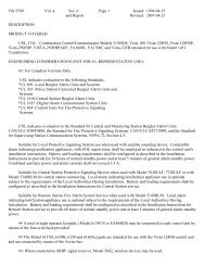
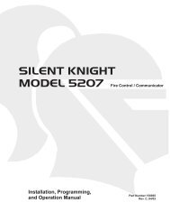
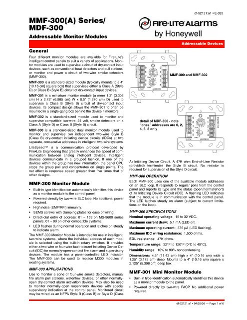
<strong>MMF</strong>-<strong>300</strong>(A) <strong>Series</strong>/<strong>MDF</strong>-<strong>300</strong>Addressable Monitor ModulesGeneralFour different monitor modules are available for Fire•Lite’sintelligent control panels to suit a variety of applications. Monitormodules are used to supervise a circuit of dry-contact inputdevices, such as conventional heat detectors and pull stations,or monitor and power a circuit of two-wire smoke detectors(<strong>MMF</strong>-302).<strong>MMF</strong>-<strong>300</strong> is a standard-sized module (typically mounts to a 4"[10.16 cm] square box) that supervises either a Class A (StyleD) or Class B (Style B) circuit of dry-contact input devices.<strong>MMF</strong>-301 is a miniature monitor module (a mere 1.3" (3.302cm) H x 2.75" (6.985 cm) W x 0.5" (1.270 cm) D) used tosupervise a Class B (Style B) circuit of dry-contact inputdevices. Its compact design allows the <strong>MMF</strong>-301 to often bemounted in a single-gang box behind the device it monitors.<strong>MMF</strong>-302 is a standard-sized module used to monitor andsupervise compatible two-wire, 24 volt, smoke detectors on aClass A (Style D) or Class B (Style B) circuit.<strong>MDF</strong>-<strong>300</strong> is a standard-sized dual monitor module used tomonitor and supervise two independent two-wire Style B(Class B) dry-contact initiating device circuits (IDCs) at twoseparate, consecutive addresses in intelligent, two-wire systems.LiteSpeed is a communication protocol developed byFire•Lite Engineering that greatly enhances the speed of communicationbetween analog intelligent devices. Intelligentdevices communicate in a grouped fashion. If one of thedevices within the group has new information, the panel CPUstops the group poll and concentrates on single points. Thenet effect is response speed greater than five times that ofother designs.<strong>MMF</strong>-<strong>300</strong> Monitor Module• Built-in type identification automatically identifies this deviceas a monitor module to the control panel.• Powered directly by two-wire SLC loop. No additional powerrequired.• High noise (EMF/RFI) immunity.• SEMS screws with clamping plates for ease of wiring.• Direct-dial entry of address: 01 – 159 on MS-9600 seriespanels, 01 – 99 on other compatible systems.• LED flashes during normal operation and latches on steadyto indicate alarm.The <strong>MMF</strong>-<strong>300</strong> Monitor Module is intended for use in intelligent,two-wire systems, where the individual address of each moduleis selected using the built-in rotary switches. It provideseither a two-wire or four-wire fault-tolerant Initiating Device Circuit(IDC) for normally-open-contact fire alarm and supervisorydevices. The module has a panel-controlled LED indicator.The <strong>MMF</strong>-<strong>300</strong> can be used to replace M<strong>300</strong> modules inexisting systems.<strong>MMF</strong>-<strong>300</strong> APPLICATIONSUse to monitor a zone of four-wire smoke detectors, manualfire alarm pull stations, waterflow devices, or other normallyopendry-contact alarm activation devices. May also be usedto monitor normally-open supervisory devices with specialsupervisory indication at the control panel. Monitored circuitmay be wired as an NFPA Style B (Class B) or Style D (Class6724mod2.tifdetail of <strong>MDF</strong>-<strong>300</strong> - note“ones” addresses are 0, 2,4, 6, 8 onlydf-52121:a1 • E-325Addressable Devices<strong>MMF</strong>-<strong>300</strong> and <strong>MMF</strong>-302A) Initiating Device Circuit. A 47K ohm End-of-Line Resistor(provided) terminates the Style B circuit. No resistor isrequired for supervision of the Style D circuit.<strong>MMF</strong>-<strong>300</strong> OPERATIONEach <strong>MMF</strong>-<strong>300</strong> uses one of the available module addresseson an SLC loop. It responds to regular polls from the controlpanel and reports its type and the status (open/normal/short)of its Initiating Device Circuit (IDC). A flashing LED indicatesthat the module is in communication with the control panel.The LED latches steady on alarm (subject to current limitationson the loop).<strong>MMF</strong>-<strong>300</strong> SPECIFICATIONSNominal operating voltage: 15 to 32 VDC.Maximum current draw: 5.1 mA (LED on).Maximum operating current: 375 µA (LED flashing).Maximum IDC wiring resistance: 1,500 ohms.EOL resistance: 47K ohms.Temperature range: 32°F to 120°F (0°C to 49°C).Humidity range: 10% to 93% noncondensing.Dimensions: 4.5" (11.43 cm) high x 4" (10.16 cm) wide x1.25" (3.175 cm) deep. Mounts to a 4" (10.16 cm) square x2.125" (5.398 cm) deep box.<strong>MMF</strong>-301 Mini Monitor Module• Built-in type identification automatically identifies this deviceas a monitor module to the panel.• Powered directly by two-wire FACP. No additional powerrequired.6720fdm1.tifdf-52121:a1 • 04/28/08 — Page 1 of 6
• High noise (EMF/RFI) immunity.• Tinned, stripped leads for ease of wiring.• Direct-dial entry of address: 01 – 159 on MS-9600 seriespanels, 01 – 99 on other compatible systems.6720m101.wmfThe <strong>MMF</strong>-301 Mini Monitor Module can be installed in a single-gangjunction directly behind the monitored unit. Its smallsize and light weight allow it to be installed without rigid mounting.The <strong>MMF</strong>-301 is intended for use in intelligent, two-wiresystems where the individual address of each module isselected using rotary switches. It provides a two-wire initiatingdevice circuit for normally-open-contact fire alarm devices.The <strong>MMF</strong>-301 can be used to replace M301 modules in existingsystems.<strong>MMF</strong>-301 APPLICATIONSUse to monitor a single device or a zone of four-wire smokedetectors, manual fire alarm pull stations, waterflow devices, orother normally-open dry-contact devices. May also be used tomonitor normally-open supervisory devices with special supervisoryindication at the control panel. Monitored circuit/deviceis wired as an NFPA Style B (Class B) Initiating Device Circuit.A 47K ohm End-of-Line Resistor (provided) terminates the circuit.<strong>MMF</strong>-301 OPERATIONEach <strong>MMF</strong>-301 uses one of the available module addresseson an SLC loop. It responds to regular polls from the controlpanel and reports its type and the status (open/normal/short)of its Initiating Device Circuit (IDC).<strong>MMF</strong>-301 SPECIFICATIONSNominal operating voltage: 15 to 32 VDC.Maximum operating current: 375 µA.Maximum IDC wiring resistance: 1,500 ohms.EOL resistance: 47K ohms.Temperature range: 32°F to 120°F (0°C to 49°C).Humidity range: 10% to 93% noncondensing.Dimensions: 1.3" (3.302 cm) high x 2.75" (6.985 cm) wide x0.65" (1.651 cm) deep.Wire length: 6" (15.24 cm) minimum.<strong>MMF</strong>-302 Interface Module• Supports compatible two-wire smoke detectors.• Supervises IDC wiring and connection of external powersource.• High noise (EMF/RFI) immunity.• SEMS screws with clamping plates for ease of wiring.• Direct-dial entry of address: 01 – 159 on MS-9600 seriespanels, 01 – 99 on other compatible systems.• LED flashes during normal operation.• LED latches steady to indicate alarm on command fromcontrol panel.The <strong>MMF</strong>-302 Interface Module is intended for use in intelligent,addressable systems, where the individual address ofeach module is selected using built-in rotary switches. Thismodule allows intelligent panels to interface and monitor twowireconventional smoke detectors. It transmits the status (normal,open, or alarm) of one full zone of conventional detectorsback to the control panel. All two-wire detectors being monitoredmust be UL compatible with the module. The <strong>MMF</strong>-302can be used to replace M302 modules in existing systems.<strong>MMF</strong>-302 APPLICATIONSUse the <strong>MMF</strong>-302 to monitor a zone of two-wire smoke detectors.The monitored circuit may be wired as an NFPA Style B(Class B) or Style D (Class A) Initiating Device Circuit. A 3.9 Kohm End-of-Line Resistor (provided) terminates the end of theStyle B or D (class B or A) circuit (maximum IDC loop resistanceis 25 ohms). Install ELR across terminals 8 and 9 forStyle D application.<strong>MMF</strong>-302 OPERATIONEach <strong>MMF</strong>-302 uses one of the available module addresseson an SLC loop. It responds to regular polls from the controlpanel and reports its type and the status (open/normal/short)of its Initiating Device Circuit (IDC). A flashing LED indicatesthat the module is in communication with the control panel.The LED latches steady on alarm (subject to current limitationson the loop).<strong>MMF</strong>-302 SPECIFICATIONSNominal operating voltage: 15 to 32 VDC.Maximum current draw: 5.1 mA (LED on).Maximum IDC wiring resistance: 25 ohms.Maximum operating current: 270 µA (LED flashing).EOL resistance: 3.9K ohms.External supply voltage (between Terminals T3 and T4):DC voltage: 24 volts power limited. Ripple voltage: 0.1 Vrmsmaximum. Current: 90 mA per module maximum.Temperature range: 32°F to 120°F (0°C to 49°C).Humidity range: 10% to 93% noncondensing.Dimensions: 4.5" (11.43 cm) high x 4" (10.16 cm) wide x1.25" (3.175 cm) deep. Mounts to a 4" (10.16 cm) square x2.125" (5.398 cm) deep box.<strong>MDF</strong>-<strong>300</strong> Dual Monitor ModuleThe <strong>MDF</strong>-<strong>300</strong> Dual Monitor Module is intended for use in intelligent,two-wire systems. It provides two independent two-wireinitiating device circuits (IDCs) at two separate, consecutiveaddresses. It is capable of monitoring normally open contactfire alarm and supervisory devices. The module has a singlepanel-controlled LED.NOTE: The <strong>MDF</strong>-<strong>300</strong> provides two Class B (Style B) IDC circuitsONLY. Class A (Style D) IDC circuits are NOT supported in anyapplication.<strong>MDF</strong>-<strong>300</strong> SPECIFICATIONSNormal operating voltage range: 15 to 32 VDC.Maximum current draw: 6.4 mA (LED on).Maximum operating current: 750 µA (LED flashing).Page 2 of 6 — df-52121:a1 • 04/28/08
Maximum IDC wiring resistance: 1,500 ohms.EOL resistance: 47K ohms.Temperature range: 32° to 120°F (0° to 49°C).Humidity range: 10% to 93% (non-condensing).Dimensions: 4.5" (11.43 cm) high x 4" (10.16 cm) wide x2.125" (5.398 cm) deep.<strong>MDF</strong>-<strong>300</strong> AUTOMATIC ADDRESSINGThe <strong>MDF</strong>-<strong>300</strong> automatically assigns itself to two addressablepoints, starting with the original address. For example, if the<strong>MDF</strong>-<strong>300</strong> is set to address “26”, then it will automaticallyassign itself to addresses “26” and “27”.NOTE: “Ones” addresses on the <strong>MDF</strong>-<strong>300</strong> are 0, 2, 4, 6, or 8 only.Terminals 6 and 7 use the first address, and terminals 8 and 9 usethe second address.!CAUTION:Avoid duplicating addresses on the system.Installation<strong>MMF</strong>-<strong>300</strong>, <strong>MMF</strong>-302, and <strong>MDF</strong>-<strong>300</strong> modules mount directly toa standard 4" (10.16 cm) square, 2.125" (5.398 cm) deep,electrical box. They may also be mounted to the SMB500 surface-mountbox. Mounting hardware and installation instructionsare provided with each module. All wiring must conformto applicable local codes, ordinances, and regulations. Thesemodules are intended for power-limited wiring only.The <strong>MMF</strong>-301 module is intended to be wired and mountedwithout rigid connections inside a standard electrical box. Allwiring must conform to applicable local codes, ordinances, andregulations.Agency Listings and ApprovalsIn some cases, certain modules may not be listed by certainapproval agencies, or listing may be in process. Consult factoryfor latest listing status.• UL: S2424• ULC: S3705• FM Approved• CSFM: 7<strong>300</strong>-0075-185• MEA: 72-01-EProduct Line Information<strong>MMF</strong>-<strong>300</strong>: Monitor module.<strong>MMF</strong>-301: Monitor module, miniature.<strong>MMF</strong>-302: Monitor module, two-wire detectors<strong>MDF</strong>-<strong>300</strong>: Monitor module, dual, two independent Class B circuits.SMB500: Optional surface-mount backbox.Architects’/Engineers’ SpecificationsSpecifications of these and all FireLite products are availablefrom FireLite.g6724face.wmf6720mt2.wmfFace plate for <strong>MMF</strong>-<strong>300</strong>, <strong>MMF</strong>-302,and <strong>MDF</strong>-<strong>300</strong>Mounting Diagrams forStandard-sized Modules6720mt1.wmfdf-52121:a1 • 04/28/08 — Page 3 of 6
Wiring DiagramsThe following wiring diagrams are included:1. <strong>MDF</strong>-<strong>300</strong>: Typical dual two-wire Style B initiating device circuit configuration.2. <strong>MMF</strong>-301: Typical two-wire Style B initiating device circuit configuration.3. <strong>MMF</strong>-<strong>300</strong>: Typical two-wire initiating circuit configuration, NFPA Style B.4. <strong>MMF</strong>-<strong>300</strong>: Typical four-wire fault-tolerant initiating circuit configuration, NFPA Style D.5. <strong>MMF</strong>-302: Interface two-wire conventional detectors, NFPA Style B.6. <strong>MMF</strong>-302: Interface two-wire conventional detectors, NFPA Style D.7. Applications with Conventional Detectors: Resetting Conventional DetectorsFigure 1 <strong>MDF</strong>-<strong>300</strong>: Typical dual two-wire Style B initiating device circuit configuration.• All shown wiring is supervised and powerlimited.• Connect modules to listed compatible Fire-Lite control panels only.6822wir1.wmfFigure 2 <strong>MMF</strong>-301: Typical two-wire Style B initiating device circuit configuration.Miniature Monitor Moduleg6720wir1.wmfPage 4 of 6 — df-52121:a1 • 04/28/08
NOTE: Wiring Diagrams this Page: <strong>MMF</strong>-302 and CRF-<strong>300</strong>• Connect modules to listed compatible control panels only.• Terminal wiring must be power limited.• DO NOT MIX fire alarm initiating and supervisory deviceson the same circuit.• DO NOT LOOP wire under terminals. Break wire run toprovide supervision of connections.Figure 5 <strong>MMF</strong>-302: Interface two-wire conventional detectors, NFPA Style B.• Detectors must be UL listed compatible with module.• Install detectors per manufacturers’ installation instructions.• Power to the interface module must be externallyswitched to reset the detectors. An relay control modulecan be used to switch power from a standard power supply;see Figure 8 below.Figure 6 <strong>MMF</strong>-302: Interface two-wire conventional detectors, NFPA Style D.6720wir5.wmf6720wir6.wmfFigure 7 Applications with Conventional Detectors: Resetting detectorsNOTE: To reset conventional detectors, externally switch off power to the interface module they are connected to. This example shows CRF-<strong>300</strong>(see DF-52130).6720wir7.wmfFire·Lite® and LiteSpeed® are registered trademarks of HoneywellInternational <strong>Inc</strong>.©2008 by Honeywell International <strong>Inc</strong>. All rights reserved. Unauthorized useof this document is strictly prohibited.This document is not intended to be used for installation purposes.We try to keep our product information up-to-date and accurate.We cannot cover all specific applications or anticipate all requirements.All specifications are subject to change without notice.For more information, contact Fire•Lite <strong>Alarm</strong>s. Phone: (800) 627-3473, FAX: (877) 699-4105.www.firelite.comMade in the U.S. A.Page 6 of 6 — df-52121:a1 • 04/28/08