ADEMCO LYNXR Series Security Systems - Patriot Alarm Systems ...
ADEMCO LYNXR Series Security Systems - Patriot Alarm Systems ...
ADEMCO LYNXR Series Security Systems - Patriot Alarm Systems ...

You also want an ePaper? Increase the reach of your titles
YUMPU automatically turns print PDFs into web optimized ePapers that Google loves.
<strong>ADEMCO</strong> <strong>LYNXR</strong> <strong>Series</strong><br />
<strong>Security</strong> <strong>Systems</strong><br />
<strong>LYNXR</strong>/<strong>LYNXR</strong>24 and <strong>LYNXR</strong>-EN<br />
Installation and Setup Guide<br />
ARMED<br />
READY<br />
OFF<br />
ESCAPE<br />
AWAY<br />
ADD<br />
STAY<br />
RECORD<br />
LIGHTS ON<br />
1 2 3<br />
VOLUME<br />
4 5 6<br />
TEST<br />
7 8 9<br />
PLAY<br />
BYPASS<br />
DELETE<br />
AUX<br />
LIGHTS OFF<br />
CODE<br />
CHIME<br />
0 #<br />
SELECT<br />
STATUS<br />
NO DELAY<br />
FUNCTION<br />
K5963V3 5/04 Rev. A
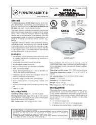
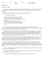
RECOMMENDATIONS FOR PROPER PROTECTION<br />
The Following Recommendations for the Location of Fire and Burglary Detection Devices Help Provide<br />
Proper Coverage for the Protected Premises.<br />
Recommendations for Smoke and Heat Detectors<br />
With regard to the number and placement of smoke/heat detectors, we subscribe to the recommendations<br />
contained in the National Fire Protection Association's (NFPA) Standard #72 noted below.<br />
• Early warning fire detection is best achieved by the installation of fire detection equipment in all rooms and areas of<br />
the household as follows: For minimum protection a smoke detector should be installed outside of each separate sleeping<br />
area, and on each additional floor of a multi-floor family living unit, including basements. The installation of smoke<br />
detectors in kitchens, attics (finished or unfinished), or in garages is not normally recommended.<br />
• For additional protection the NFPA recommends that you install heat or smoke detectors in the living room, dining<br />
room, bedroom(s), kitchen, hallway(s), attic, furnace room, utility and storage rooms, basements and attached garages.<br />
In addition, we recommend the following:<br />
• Install a smoke detector inside every bedroom where a smoker sleeps.<br />
• Install a smoke detector inside every bedroom where someone sleeps with the door partly or completely closed. Smoke<br />
could be blocked by the closed door. Also, an alarm in the hallway outside may not wake up the sleeper if the door is<br />
closed.<br />
• Install a smoke detector inside bedrooms where electrical appliances (such as portable heaters, air conditioners or<br />
humidifiers) are used.<br />
• Install a smoke detector at both ends of a hallway if the hallway is more than 40 feet (12 meters) long.<br />
• Install smoke detectors in any room where an alarm control is located, or in any room where alarm control connections<br />
to an AC source or phone lines are made. If detectors are not so located, a fire within the room could prevent the control<br />
from reporting a fire or an intrusion.<br />
THIS CONTROL COMPLIES WITH NFPA REQUIREMENTS FOR TEMPORAL PULSE<br />
SOUNDING OF FIRE NOTIFICATION APPLIANCES.<br />
DINING<br />
KITCHEN<br />
BEDROOM<br />
BEDROOM<br />
TV ROOM<br />
KITCHEN<br />
DINING<br />
LIVING ROOM<br />
BEDROOM<br />
BEDROOM<br />
LIVING ROOM<br />
BEDROOM<br />
BEDROOM<br />
Smoke Detectors for Minimum Protection<br />
Smoke Detectors for Additional Protection<br />
BEDROOM<br />
Heat-Activated Detectors<br />
BEDROOM<br />
BEDROOM<br />
LIVING<br />
ROOM<br />
KTCHN<br />
.<br />
CLOSED<br />
DOOR<br />
GARAGE<br />
TO<br />
BEDROOM<br />
BASEMENT<br />
01000-002-V0<br />
Recommendations For Proper Intrusion Protection<br />
• For proper intrusion coverage, sensors should be located at every possible point of entry to a home or premises. This<br />
would include any skylights that may be present, and the upper windows in a multi-level building.<br />
• In addition, we recommend that radio backup be used in a security system. This will ensure that alarm signals can be<br />
sent to the alarm monitoring station in the event that the telephone lines are out of order (alarm signals are normally<br />
sent over the phone lines, if connected to an alarm monitoring station).<br />
–2–
Table of Contents<br />
SYSTEM FEATURES ...............................................................................................................................................4<br />
MOUNTING THE CONTROL..................................................................................................................................5<br />
WIRING CONNECTIONS........................................................................................................................................6<br />
AC POWER AND BACKUP BATTERY...................................................................................................................9<br />
INSTALLING WIRELESS ZONES........................................................................................................................11<br />
MECHANICS OF PROGRAMMING .....................................................................................................................14<br />
ZONE RESPONSE TYPE DEFINITIONS ............................................................................................................15<br />
DATA FIELD DESCRIPTIONS .............................................................................................................................17<br />
✻56 ENHANCED ZONE PROGRAMMING MODE .............................................................................................25<br />
✻80 DEVICE PROGRAMMING MENU MODE ...................................................................................................29<br />
✻81 ZONE LIST MENU MODE.............................................................................................................................32<br />
✻83 ENHANCED SEQUENTIAL MODE .............................................................................................................33<br />
✻84 ASSIGN ZONE VOICE DESCRIPTORS .......................................................................................................36<br />
✻85 RECORD CUSTOM VOICE DESCRIPTORS................................................................................................38<br />
VOICE PROMPT PROGRAMMING......................................................................................................................39<br />
REMOTE PROGRAMMING/CONTROL (DOWNLOADING) .............................................................................43<br />
SYSTEM OPERATION...........................................................................................................................................45<br />
TESTING THE SYSTEM........................................................................................................................................51<br />
SYSTEM COMMUNICATION ...............................................................................................................................52<br />
TROUBLESHOOTING GUIDE .............................................................................................................................54<br />
CONTACTING TECHNICAL SUPPORT..............................................................................................................56<br />
REGULATORY AGENCY STATEMENTS ...........................................................................................................57<br />
SPECIFICATIONS..................................................................................................................................................58<br />
<strong>LYNXR</strong>/<strong>LYNXR</strong>24 PROGRAMMING DEFAULT TABLES.................................................................................59<br />
<strong>LYNXR</strong>-EN PROGRAMMING DEFAULT TABLES ............................................................................................60<br />
INDEX......................................................................................................................................................................63<br />
LIMITATIONS OF THIS SYSTEM STATEMENT...............................................................................................69<br />
WARRANTY ............................................................................................................................................................70<br />
SUMMARY OF CONNECTIONS DIAGRAM .......................................................................................................71<br />
–3–
System Features<br />
UL<br />
<strong>LYNXR</strong> and <strong>LYNXR</strong>-EN are not intended for UL985 Household Fire applications unless a 24-hour backup<br />
battery (P/N <strong>LYNXR</strong>CHKIT-HC) is installed.<br />
Powerline Carrier Devices are not UL Listed for fire or burglary functions and are intended for home<br />
automation.<br />
The <strong>LYNXR</strong>-<strong>Series</strong> controls are self-contained, rechargeable wireless control/communicators that feature easy<br />
installation and usage. A built-in speaker provides voice annunciation of system status along with voice descriptors of<br />
each zone (<strong>LYNXR</strong>-EN if programmed). The following illustration highlights the main features of this system.<br />
ZONES and DEVICES<br />
• 1 hardwire zone<br />
• Up to 24 wireless zones<br />
(5800 <strong>Series</strong> Transmitters)<br />
• Up to 16 wireless button zones<br />
• Up to 8 Powerline Carrier Devices<br />
• Supports wireless keypads<br />
FEATURES<br />
• Real-time Clock display and Fixed-Word display<br />
• Message Center (for user recorded messages)<br />
• Voice announcement of system and zone status<br />
• Voice chime<br />
• <strong>Alarm</strong> Clock<br />
• Reminder<br />
• X-10 Scheduling<br />
• Latch Key Reports<br />
• Automatic Stay Arming<br />
• Remote Phone Control<br />
• “Follow Me” Reminder and System Announcements<br />
SYSTEM POWER<br />
• Primary Power: Ademco<br />
1332/1332X10 Plug-in Transformer,<br />
110VAC to 9VAC, 15VA output<br />
(1332CN in Canada)<br />
• Backup battery: Six 1.2V<br />
rechargeable nickel-metal hydride<br />
batteries.<br />
8 USER CODES<br />
• Installer code<br />
• Master code<br />
• 5 Secondary codes<br />
• Duress code<br />
• 3 Panic functions<br />
ARMED<br />
READY<br />
OFF<br />
1 2 3<br />
COMMUNICATION<br />
• Ademco Low Speed<br />
• Sescoa/Radionics<br />
• Ademco Express<br />
• Ademco Contact ID<br />
• Paging feature<br />
ESCAPE<br />
AWAY<br />
ADD<br />
STAY<br />
DELETE<br />
AUX<br />
RECORD VOLUME<br />
LIGHTS ON<br />
LIGHTS OFF<br />
4 5 6<br />
CODE<br />
TEST<br />
7 8 9<br />
SELECT<br />
STATUS NO DELAY FUNCTION<br />
PLAY<br />
BYPASS<br />
CHIME<br />
0 #<br />
ALARM OUTPUT<br />
• Built-in sounder<br />
• Piezo output<br />
(30mA max.)<br />
• Bell output<br />
(120mA max.)<br />
• Steady output for<br />
burglary/panic<br />
• Temporal pulse<br />
output for fire alarms<br />
• Long Range<br />
Radio/<strong>Alarm</strong> audio<br />
verification<br />
PROGRAMMING<br />
• Options stored in EEROM<br />
• Can be uploaded, downloaded or<br />
controlled via IBM-compatible<br />
computer using Compass<br />
downloader software and specified<br />
HAYES modem<br />
• Voice Prompt programming mode<br />
OTHER FEATURES<br />
• Exit error feature (detects difference between an<br />
actual alarm and exit alarm caused by leaving a door<br />
open after the exit delay expires)<br />
• Event log stores up to 84 events<br />
• Macro/ 1-button paging<br />
• RF Jam Detection<br />
• Remote Phone Control<br />
• Compatible with Encrypted (High-<strong>Security</strong>) Devices<br />
SPECIAL FEATURES<br />
<strong>LYNXR</strong>24<br />
• 24-hour backup<br />
<strong>LYNXR</strong>-EN<br />
• Two-way voice communication<br />
• Speaker phone operation<br />
–4–
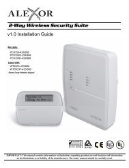
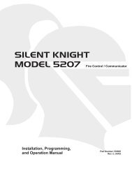
Wall Mounting<br />
The illustration below shows the front assembly separated from the back plate.<br />
Mounting the Control<br />
!<br />
DO NOT disconnect the ribbon cable from the terminal strip board. Disconnect the cable only from the<br />
front assembly board.<br />
Certain features differ between the <strong>LYNXR</strong>/<strong>LYNXR</strong>24 and the <strong>LYNXR</strong>-EN models. Verify the specific model<br />
being installed prior to programming the system.<br />
1. Separate the front assembly from the<br />
back plate by pressing on the two<br />
locking tabs at the top of the unit.<br />
LOCKING TABS<br />
2. Carefully disconnect the ribbon cable<br />
from the front assembly, leaving the<br />
ribbon cable connected to the<br />
terminal block PC board. The back<br />
plate contains the terminal block for<br />
making wiring connections.<br />
PC BOARD<br />
PART NUMBER<br />
LOCATION<br />
1<br />
16<br />
MXXXX<br />
K5108<br />
3. Mount the back plate to a sturdy wall,<br />
feeding the field wiring through the<br />
appropriate openings in the back<br />
plate.<br />
4. After wiring connections are made,<br />
carefully reconnect the ribbon cable to<br />
the front assembly PC board<br />
connector (properly aligning the red<br />
wire).<br />
RED WIRE<br />
MARKING<br />
5. Before closing the assembly, verify<br />
which <strong>LYNXR</strong> model is being installed<br />
by checking the model number printed<br />
on the PC Boards. (Example:<br />
SA<strong>LYNXR</strong>EN indicates the unit being<br />
installed is a <strong>LYNXR</strong>-EN.)<br />
6. Snap the front assembly to the back<br />
plate so it is secured by the locking<br />
tabs.<br />
DISCONNECT<br />
THIS END ONLY!<br />
PC BOARD<br />
PART NUMBER<br />
LOCATION<br />
01009-003-V0<br />
Desktop Mounting<br />
If desired, an optional mounting base (model LYNX-DM, purchased separately) allows the <strong>LYNXR</strong>-<strong>Series</strong> controls to be<br />
used on a desktop.<br />
1. Slide the control panel onto the<br />
mounting base locking tabs.<br />
2. Bring all wiring through the bottom of<br />
the mounting base, using one of the<br />
three wire entry locations, before<br />
making connections to the control<br />
panel.<br />
OFF<br />
ESCAPE<br />
AWAY<br />
ADD<br />
STAY<br />
DELETE<br />
AUX<br />
SELECT<br />
3. Use tie-wraps to secure the wiring to<br />
the built-in wire loops as needed. Use<br />
the two supplied screws to secure the<br />
control panel to the mounting base.<br />
WIRE ENTRY<br />
KNOCKOUT<br />
(1 of 3)<br />
01009-004-V1<br />
–5–
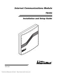
Wiring Connections<br />
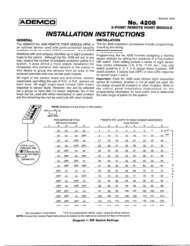
Wiring Overview<br />
The following summarizes the connections required. Refer to the Wiring Connections paragraph and the Summary of<br />
Connections diagram on the inside back cover when making connections.<br />
HARDWIRE ZONE<br />
Supports 1 EOLR supervised zone using either closed<br />
circuit or open circuit sensors.<br />
LONG RANGE RADIO<br />
Compatible with the ALARMNET 7845C and 7720<br />
Devices.<br />
TWO-WAY VOICE<br />
The <strong>LYNXR</strong>-EN supports the two-way<br />
voice feature/<strong>Alarm</strong> Audio Verification.<br />
The <strong>LYNXR</strong> and <strong>LYNXR</strong>24 require the<br />
installation of the LYNXAVM.<br />
POWERLINE CARRIER DEVICES<br />
Supports up to 8 Powerline Carrier<br />
Devices for turning on/off lights and<br />
appliances. Requires the use of an<br />
<strong>ADEMCO</strong> 1332X10 transformer.<br />
PHONE LINES<br />
Use either the plug-in jacks or<br />
the screw terminals.<br />
MXXXX<br />
K5108<br />
AC TRANSFORMER<br />
Use the supplied<br />
<strong>ADEMCO</strong> 1332X10<br />
9VAC, 15VA Plug-in<br />
Transformer (1332CN in<br />
Canada).<br />
01009-005-V0<br />
EARTH GROUND<br />
See Earth Ground paragraph.<br />
LOCAL SOUNDER DISABLE JUMPER<br />
Remove the shorting jumper (shunt) to disable local<br />
sounder, leaving only the external sounder active.<br />
UL NOTE: Do not remove the shorting jumper (the shunt)<br />
for UL installations.<br />
SOUNDERS<br />
The system includes a built-in sounder in the master keypad. If<br />
desired, an external bell or piezo sounder can be connected.<br />
Bell: Use a 6-14V bell with maximum current drain of 120mA.<br />
Piezo: Use a 6-14V piezo sounder with maximum current drain of<br />
30mA.<br />
This control complies with NFPA requirements for temporal pulse<br />
sounding of fire notification appliances.<br />
Temporal pulse sounding for a fire alarm consists of the following:<br />
3 pulses – pause – 3 pulses – pause – 3 pulses. . .<br />
Wiring Connections<br />
1. Make Earth Ground Connection - The designated earth ground terminal (1) must be terminated in a good earth ground<br />
for the lightning transient protective devices in this product to be effective. The following are examples of good earth<br />
grounds available at most installations:<br />
Metal Cold Water Pipe - Secure a non-corrosive metal strap (copper is recommended) to the pipe that is electrically<br />
connected and secured to which the ground lead.<br />
AC Power Outlet Ground - Available from 3-prong, 120VAC power outlets only. To test the integrity of the ground<br />
terminal, use a three-wire circuit tester with neon lamp indicators, such as the UL Listed Ideal Model 61–035, or<br />
equivalent, available at most electrical supply stores.<br />
a. Connect terminal 1 to a good earth ground.<br />
–6–
Wiring Connections<br />
Wiring Connections<br />
2. Make Phone Line Connections - For local or full line<br />
seizure proceed to the appropriate steps below.<br />
Local Seizure<br />
a. Connect the incoming phone line to either the<br />
8-position jack or terminals 2 (TIP) and 3 (RING) on<br />
the Lynx.<br />
b. Connect the handset phone lines to either the RJ11<br />
jack or terminals 4 (TIP) and 5 (RING).<br />
Full Line Seizure: The control must be placed in<br />
series with the incoming phone line. Plugging the<br />
Direct Connect Cord directly into the RJ31X jack, allows<br />
the control to seize the phone line when an alarm<br />
occurs and normal phone line usage by the premises<br />
phones if the plug needs to be removed.<br />
a. Cut the incoming RING and TIP phone lines<br />
(typically red and green, respectively) and connect<br />
them to RJ31X terminals 4 (red) and 5 (green).<br />
b. Connect the premises end of the cut RING and TIP<br />
wires to RJ31X terminals 1 (grey) and 8 (brown)<br />
respectively.<br />
c. Wire the flying leads of a Direct Connect Cord to the<br />
control’s phone terminals as shown in the diagram<br />
or plug into the 8-position jack.<br />
d. Plug the Direct Connect Cord into the RJ31X jack.<br />
GREEN<br />
RED<br />
RED<br />
GREY<br />
BROWN<br />
4 5<br />
3 6<br />
RJ31X<br />
2<br />
1<br />
GREY<br />
TIP RING TIP RING<br />
INCOMING<br />
PHONE LINE<br />
OR<br />
}<br />
}<br />
TO<br />
PREMISES<br />
PHONES<br />
7<br />
8<br />
INCOMING<br />
PHONE LINE<br />
RING<br />
TIP<br />
GREEN<br />
DIRECT<br />
CONNECT<br />
CORD<br />
TO<br />
PREMISES PHONES<br />
RING<br />
TIP<br />
BROWN<br />
8-POSITION<br />
JACK<br />
Full Line Seizure Connections<br />
01000-008-V0<br />
HARDWIRED ZONE: If the EOLR is not at the end of the loop, the zone will not be properly<br />
supervised, and the system may not respond to an open circuit on the zone.<br />
3. Make Hardwired Zone Connections - Zone 1 is an EOLR supervised zone that supports both open circuit and closed<br />
circuit devices and has a response time of 350msec. Maximum zone resistance: 300 ohms, plus EOLR<br />
Note: The hardwire zone cannot be used as a fire zone.<br />
a. Connect sensors/contacts to the hardwired zone terminals 6 (+) and 7 (–). Refer to the Summary of Connections<br />
diagram.<br />
b. Connect closed circuit devices in series in the high (+) side of the loop. The EOL resistor must be connected in<br />
series with the devices, following the last device.<br />
c. Connect open circuit devices in parallel across the loop. The 2000-ohm EOLR must be connected across the loop<br />
at the last device.<br />
4. Make External Sounder Connections - The control panel supports either a 6-14VDC piezo sounder (30mA max.) or<br />
6-14VDC bell (120mA max.; e.g. <strong>ADEMCO</strong> WAVE2EX).<br />
a. Connect a piezo sounder to terminals 10 (+) and 11 (–); OR a bell to terminals 11 (–) and 12 (+).<br />
LOCAL SOUNDER DISABLE: The Master Keypad’s built-in piezo sounder can be disabled by<br />
removing the shorting jumper (shunt) on the terminal board. If disabled, however, no sounding<br />
will occur upon AC loss, since the external sounder does not operate when AC power is lost.<br />
U L Do not remove shorting jumper (the shunt) for UL installations.<br />
5. Disable Local Sounder Option - If required the Master Keypad’s built-in piezo sounder can be disabled.<br />
a. Remove the shorting jumper (shunt) on the terminal board.<br />
6. Make Powerline Carrier Device Connections - The control panel supports up to 8 Powerline Carrier Devices. If using<br />
these devices, they must be connected to the <strong>ADEMCO</strong> 1332X10 transformer, as shown in the SUMMARY OF<br />
CONNECTIONS diagram.<br />
a. Connect the com/data/sync/ lines from the <strong>ADEMCO</strong> 1332X10 transformer to terminals 9, 13, and 14, respectively.<br />
Note: If not using the supplied Ademco connection cable, you may need to reverse the black and yellow wire connections. Refer to the<br />
✻80 Device Programming Menu Mode section for details on programming Powerline Carrier Devices.<br />
–7–
Wiring Connections<br />
WARNING:<br />
TO PREVENT RISK OF SHOCK<br />
DISCONNECT TELEPHONE LINE<br />
AT TELECOM JACK BEFORE<br />
SERVICING THIS UNIT.<br />
EARTH<br />
GROUND<br />
PHONE<br />
ALL OUTPUT CIRCUITS ARE POWER LIMITED.<br />
ZONE<br />
AAV / LRR<br />
TRIGGER<br />
(<strong>LYNXR</strong>/LYNR24)<br />
LRR<br />
TRIGGER<br />
(<strong>LYNXR</strong>-EN) SOUNDERS PLCD AC<br />
RJ11<br />
8<br />
POS<br />
JACK<br />
TO INCOMING<br />
HANDSET PHONE<br />
PHONE LINE<br />
LINE<br />
1 2 3 4 5 6 7 8 9 10 11 12 13 14 15 16<br />
TIP RING TIP RING (+) ( ) ( ) (+) ( ) (+)<br />
HARD<br />
WIRED<br />
ZONE<br />
DATA SYNC<br />
OUT IN<br />
POWERLINE<br />
CARRIER DEVICES<br />
LOCAL SOUNDER<br />
DISABLE SHUNT<br />
REMOVE TO<br />
DISABLE<br />
EARTH<br />
GROUND<br />
INCOMING<br />
TELEPHONE<br />
LINE<br />
THE LYNX SERIES CONTROLS ARE<br />
EQUIPPED WITH AN INTEGRAL<br />
RECHARGEABLE BATTERY PACK.<br />
<strong>LYNXR</strong>: P/N <strong>LYNXR</strong>CHKIT-SC<br />
<strong>LYNXR</strong>24: P/N <strong>LYNXR</strong>CHKIT-HC<br />
<strong>LYNXR</strong>-EN: P/N <strong>LYNXR</strong>CHKIT-SC<br />
OR<br />
P/N <strong>LYNXR</strong>CHKIT-HC<br />
REPLACE EVERY FOUR YEARS<br />
PREMISES<br />
TELEPHONE<br />
2k OHMS<br />
EOLR<br />
WEEKLY TESTING IS<br />
REQUIRED TO ENSURE<br />
PROPER OPERATION<br />
OF THIS SYSTEM<br />
TRIGGER<br />
SIGNAL<br />
(NEG)<br />
PIEZO<br />
BELL<br />
6-14VDC<br />
30mA max.<br />
6-14VDC<br />
120mA max.<br />
(e.g. WAVE2EX)<br />
NOTE<br />
USE ONLY 1332/1332X10 OR 1332CN<br />
TRANSFORMERS PROVIDED<br />
1332/<br />
1332X10/<br />
1332CN<br />
PLUG-IN<br />
TRANSFORMER<br />
9VAC, 15VA<br />
AC<br />
AC<br />
SYNC<br />
COM<br />
DATA<br />
1332X10<br />
ONLY<br />
CONNECTIONS<br />
01009-009-V0<br />
–8–
AC Power and Backup Battery<br />
The system is powered by a 9VAC, 15VA Plug-in Transformer, <strong>ADEMCO</strong> 1332/1332X10 (1332CN in<br />
Canada). Refer to the wiring table below for wire gauge and length.<br />
Use only the provided <strong>ADEMCO</strong><br />
1332/1332X10 or 1332CN Transformer<br />
Distance from Transformer Wire Gauge<br />
to Control<br />
Up to 75 feet #20<br />
75 to 150 feet #18<br />
150 to 300 feet #16<br />
Wiring to the AC Transformer must not exceed 300 feet using 16-gauge wire. The voltage reading between<br />
terminals 15 and 16 of the control must not fall below 9.00VAC.<br />
Do not plug the transformer into the AC outlet until after all wiring connections have been made.<br />
Backup battery. In the event of an AC power loss, the system is supported by a long life backup battery that<br />
is supervised for connection and for low voltage conditions. If the battery is missing, or a low battery condition<br />
is detected, a “low battery” message is displayed and a report is sent to the central station. In addition, the<br />
system will beep once every 45 seconds to audibly indicate a low battery condition (press any key to stop the<br />
beeping).<br />
AC Power and Rechargeable Backup Battery<br />
Connecting AC Power and backup battery<br />
1. Connect wires from the 1332/1332X10 (1332CN in<br />
Canada) AC Transformer to terminals 15 and 16 as<br />
shown in the wiring diagram.<br />
RETAINER<br />
NOTE<br />
<strong>LYNXR</strong>CHKIT-HC<br />
BATTERY PACK SHOWN<br />
2. Remove battery retainer.<br />
BATTERY<br />
PACK<br />
3. Peel the backing from tape on the back plate.<br />
4. Insert battery pack into back plate.<br />
5. Install battery retainer.<br />
TAPE<br />
6. Connect battery connector to receptacle on<br />
terminal block PC board.<br />
7. After all wiring connections have been made, snap<br />
the front assembly to the back plate and plug the<br />
transformer into a 24-hour, 110VAC unswitched<br />
outlet.<br />
1<br />
16<br />
MXXXX<br />
K5108<br />
Note:<br />
Rechargeable batteries may take up to 48-hours to<br />
fully charge. The “LOW BAT” message should clear<br />
within four hours or by entering Test Mode.<br />
BATTERY<br />
RECEPTACLE<br />
WIRING<br />
TERMINALS<br />
01009-007-V0<br />
Ensure the cover is snapped closed prior to applying AC power.<br />
–9–
AC Power and Backup Battery<br />
AC Power and Rechargeable Backup Battery<br />
The <strong>LYNXR</strong> <strong>Series</strong> is equipped with an integral, replaceable, rechargeable battery pack composed of six (6)<br />
rechargeable 1.2-volt nickel-metal hydride batteries. Select the appropriate battery pack, based on the<br />
installation’s requirement, and install the battery pack.<br />
Model/Part Number Battery StandbyTime Low Battery Notification<br />
<strong>LYNXR</strong>CHKIT-SC 4-hours (minimum) Approximately 1-hour before battery depletion<br />
<strong>LYNXR</strong>CHKIT-HC 24-hours (minimum) At least 1-hour before battery depletion<br />
Replacing the Rechargeable Battery<br />
1. When battery replacement is required, unplug<br />
the transformer from the wall outlet, and open<br />
the control panel cover.<br />
2. Remove the battery retainer and disconnect the<br />
battery pack connector from the receptacle on<br />
the terminal block PC board.<br />
3. Remove the battery pack from the back plate.<br />
4. If required, replace the tape that secures the<br />
battery pack.<br />
5. Install a replacement battery pack (P/N<br />
<strong>LYNXR</strong>CHKIT-SC or <strong>LYNXR</strong>CHKIT-HC) into the<br />
back plate.<br />
6. Install the battery retainer.<br />
7. Connect the battery connector to the<br />
receptacle on the terminal block PC board.<br />
8. After the wiring connection has been made,<br />
snap the front assembly to the back plate.<br />
9. Plug the transformer into a 24-hour, 110VAC<br />
unswitched outlet.<br />
10. Rechargeable batteries may take up to 48-<br />
hours to fully charge. The “LOW BAT” message<br />
should clear within four hours or by entering<br />
Test Mode.<br />
RETAINER<br />
BATTERY<br />
PACK<br />
BATTERY<br />
RECEPTACLE<br />
BATTERY<br />
CONNECTOR<br />
<strong>LYNXR</strong>CHKIT-HC OR <strong>LYNXR</strong>CHKIT-SC<br />
TAPE<br />
MXXXX<br />
K5108<br />
01009-006-V0<br />
Ensure the control panel assembly is snapped closed prior to applying AC power.<br />
–10–
Installing Wireless Zones<br />
General Information<br />
Zones: The control supports up to 24 wireless zones using 5800 <strong>Series</strong> transmitters, and up to 16<br />
wireless buttons.<br />
Range: The built-in RF receiver can detect signals from wireless transmitters within a nominal<br />
range of 200 feet.<br />
Transmitters: 5800 <strong>Series</strong> transmitters have built-in serial numbers that must be entered into the<br />
system using the ✻56 or ✻83 interactive mode, or input to the control via the downloader. 5800<br />
<strong>Series</strong> transmitters (except the 5800RL, which is described separately) do not have DIP switches.<br />
Each transmitter's zone number is programmed into the system in ✻56 mode. Some transmitters,<br />
such as the 5816 and 5817, can support more than one "zone" (referred to as loops or inputs). On the<br />
5816, for example, the wire connection terminal block is loop 1,the reed contact is loop 2. Each loop<br />
must be assigned a different zone number.<br />
UL<br />
The 5816 and 5817 Transmitters do not have EOL supervision of their loop wiring. Therefore, for<br />
UL Household Burglary installations, the loop wiring may not exceed 3 feet.<br />
The 5800RL, 5802MN, 5802MN2, 5804, 5804BD, 5804BDV, 5804E, 5804WATCH, 5814, 5816TEMP,<br />
5819, 5819S(WHS & BRS), 5828/5828V and 5850(GBD) transmitters are not intended for any UL<br />
installations.<br />
For button transmitters (RF "keys") such as the 5804 and 5801, you must assign a unique zone<br />
number to each individual button used on the transmitter. Each button on the transmitter also has<br />
a pre-designated loop or input number, which is automatically displayed.<br />
House Identification<br />
If you are using a 5804BD/5804BDV Wireless Keypad with the system, you must program a House<br />
ID Code (01–31) in field ✻24 to establish proper communication, and the keypad must be set to the<br />
same ID. House ID 00 disables all wireless keypads. An RF House ID is not necessary for other 5800<br />
<strong>Series</strong> transmitters; the entry should be left at “00” (default) in those cases.<br />
Transmitter Supervision<br />
Except for some transmitters/keypads that may be carried off-premises (5804, 5804BD, 5804BDV,<br />
5804E, and 5804WATCH), each transmitter is supervised by a check-in signal that is sent to the<br />
receiver at 70–90 minute intervals. If at least one check-in is not received from each supervised<br />
transmitter within a 12-hour period, the "missing" transmitter number(s) and "FAULT" will be<br />
displayed. The supervision for a particular transmitter in the system that may also be carried off<br />
the premises (5801, 5802MN) may be turned off by entering it as a "UR" (unsupervised RF) type, as<br />
described in the ✻56 Enhanced Zone Programming Mode section.<br />
5800 <strong>Series</strong> transmitters have built-in tamper protection and will annunciate as a fault condition if<br />
covers are removed.<br />
Transmitter Input Types<br />
Each of the following transmitters has one or more unique factory-assigned input (loop) ID codes.<br />
Each of the inputs requires a programming zone (e.g., a 5804's four inputs require four button zones).<br />
Transmitters can be entered as one of the following types (see transmitter’s instructions for appropriate<br />
input type):<br />
Type<br />
Description<br />
"RF" (Supervised RF)<br />
Sends periodic check-in signals, as well as fault, restore, and low battery<br />
signals. The transmitter must remain within the receiver's range.<br />
"UR" (Unsupervised RF) Sends all the signals that the "RF" type does, but the control does not<br />
supervise the check-in signals. The transmitter may therefore be carried<br />
off-premises.<br />
"BR" (Unsupervised Button RF) These only send fault signals. They do not send low battery signals until<br />
they are activated. The transmitter may be carried off-premises.<br />
–11–
Installing Wireless Zones<br />
Transmitter Battery Life<br />
• Batteries in the wireless transmitters may last from 4–7 years, depending on the environment,<br />
usage, and the specific wireless device being used. Factors such as humidity, high or low<br />
temperatures, as well as large swings in temperature may all reduce the actual battery life in a<br />
given installation. The wireless system can identify a true low battery situation, thus allowing the<br />
dealer or user of the system time to arrange a change of battery and maintain protection for that<br />
point within the system.<br />
• Button-type transmitters should be periodically tested for battery life. The 5801, 5802MN,<br />
5802MN2, 5804, 5804BD, 5804BDV, 5804E, and 5804WATCH button transmitters have<br />
replaceable batteries.<br />
Using the Transmitter Sniffer Mode<br />
Use this mode after all transmitters have been entered to check that all transmitters have been<br />
properly programmed.<br />
1. Enter Installer code (4112) + [#] + 3.<br />
Note: If the communicator is in the process of sending a report to the central station, the system will not go into the Sniffer mode.<br />
If so, wait a few minutes and try again.<br />
2. The keypad will display all zone numbers, which have a non-zero Zone Type (even if serial<br />
numbers were not learned yet). Fault each transmitter in turn, causing each one to send a<br />
signal. As the system receives a signal from each of the transmitters, the zone number of that<br />
transmitter will disappear from the display. The transmitters may be checked upon<br />
installation, or in an installed system.<br />
3. When all transmitters have been checked, exit Sniffer mode. Enter Installer Code (4112) +<br />
OFF.<br />
Notes: (1) Sniffer mode does not automatically expire. You must manually exit (Installer Code + OFF) Sniffer mode to return to<br />
normal operation.<br />
(2) All BR-type units must physically be activated to clear the display, since they do not automatically send check-in<br />
signals.<br />
(3) When one button of a transmitter (RF, UR, or BR) is activated, all zones assigned to other buttons on that transmitter<br />
are cleared. This also applies to 5816 and 5817 transmitters that have multiple loops (zones).<br />
(4) Any transmitter that is not “entered” will not turn off its zone number.<br />
Go/No Go Test Mode<br />
Note: 5804E and 5804WATCH encrypted (High-<strong>Security</strong>) devices must be activated while the system is in Go/No Go Test Mode.<br />
Refer to the transmitter’s installation instructions for complete details. The system will confirm enrollment of the encrypted<br />
device by beeping two times.<br />
The Go/No Go tests will verify adequate RF signal strength from the proposed transmitter location,<br />
and allow you to reorient or relocate transmitters if necessary, before mounting the transmitters<br />
permanently. This mode is similar to the transmitter Test mode, except that the wireless receiver<br />
gain is reduced. This will enable you to make sure that the RF signal from each transmitter is<br />
received with sufficient signal amplitude when the system is in the normal operating mode.<br />
1. Enter Installer Code (4112) + [#] + 8.<br />
2. Once you have placed transmitters in their desired locations and the approximate length of wire<br />
to be run to sensors is connected to the transmitter's screw terminals (if used), fault each<br />
transmitter.<br />
Conducting this test with your hand wrapped around the transmitter will cause inaccurate results.<br />
Note: On button type transmitters that have been programmed to set ARM AWAY, ARM STAY, or DISARM, pressing a button will<br />
take the system out of the Go/No Go Test mode and cause the programmed action.<br />
a. The keypad will beep three times indicating signal reception and will display the appropriate<br />
zone number.<br />
b. If the keypad does not beep, reorient or move the transmitter to another location. Usually a<br />
few inches in either direction is all that is required.<br />
4. If each transmitter produces the proper keypad response when it is faulted, you can then<br />
permanently mount each of the transmitters according to the instructions provided with them.<br />
5. Exit the Go/No Go Test mode by entering: Installer Code (4112) + OFF.<br />
–12–
Installing Wireless Zones<br />
5800 <strong>Series</strong> Transmitter Loop Numbers (Refer to this information when programming transmitters)<br />
The following illustration shows the compatible transmitters, their associated input types and loop<br />
designations.<br />
Notes: (1) Loop 4 must be enrolled on the 5801, 5804, 5804BD, 5804BDV, 5804E and 5804WATCH transmitters, whether or not the loop is<br />
used.<br />
(2) 5804E and 5804WATCH encrypted (High-<strong>Security</strong>) devices must be activated while the system is in Go/No Go Test Mode. Refer<br />
to the transmitter’s installation instructions for complete details. The system will confirm enrollment of the encrypted device by<br />
beeping two times.<br />
UL<br />
The 5800RL, 5802MN, 5802MN2, 5804, 5804BD, 5804BDV, 5804E, 5804WATCH, 5814, 5816TEMP, 5819, 5819S(WHS<br />
& BRS), 5828/5828V and 5850(GBD) wireless transmitters are not intended for any UL installations.<br />
Setting DIP Switches on the 5800RL Transmitter<br />
Set the 5800RL Transmitters to the programmed House ID, by using the DIP switches.<br />
(OFF position is indicated by ---)<br />
Note: The 5800RL cannot be used in conjunction with the Auto Arm (scheduled arming) feature.<br />
1<br />
SW-1 ACTIVATES<br />
MODE SETTING<br />
2 3 4 5 6<br />
SHOWN SET FOR HOUSE ID# 12<br />
SWITCH UP FOR "ON"<br />
SW-6 SETS<br />
MODE<br />
2-6 SETS HOUSE ID<br />
SWITCH DOWN<br />
FOR "OFF"<br />
01000-014-V1<br />
5800RL DIP SWITCH TABLE<br />
House DIP SWITCH POSITIONS House<br />
DIP SWITCH POSITIONS<br />
ID 2 3 4 5 6 ID 2 3 4 5 6<br />
0 --- --- --- --- --- 16 ON --- --- --- ---<br />
1 --- --- --- --- ON 17 ON --- --- --- ON<br />
2 --- --- --- ON --- 18 ON --- --- ON ---<br />
3 --- --- --- ON ON 19 ON --- --- ON ON<br />
4 --- --- ON --- --- 20 ON --- ON --- ---<br />
5 --- --- ON --- ON 21 ON --- ON --- ON<br />
6 --- --- ON ON --- 22 ON --- ON ON ---<br />
7 --- --- ON ON ON 23 ON --- ON ON ON<br />
8 --- ON --- --- --- 24 ON ON --- --- ---<br />
9 --- ON --- --- ON 25 ON ON --- --- ON<br />
10 --- ON --- ON --- 26 ON ON --- ON ---<br />
11 --- ON --- ON ON 27 ON ON --- ON ON<br />
12 --- ON ON --- --- 28 ON ON ON --- ---<br />
13 --- ON ON --- ON 29 ON ON ON --- ON<br />
14 --- ON ON ON --- 30 ON ON ON ON ---<br />
15 --- ON ON ON ON 31 ON ON ON ON ON<br />
Setting 5800RL DIP Switches<br />
–13–
Mechanics of Programming<br />
General Programming Information<br />
Programming options are stored in non-removable, electrically erasable, nonvolatile EEROM memory.<br />
The system can be programmed at any time, even at the installer's premises prior to the actual<br />
installation. Simply apply power temporarily to the Control and then program the unit as desired.<br />
There are two programming modes:<br />
• Data field programming (used for setting various system options)<br />
• Interactive menu mode programming (used for programming zone information, programming Powerline<br />
Carrier Devices, and for entering transmitter serial numbers)<br />
The system can also be programmed remotely, using an IBM Personal Computer, a modem, and Compass<br />
Downloader for Windows. See the Remote Programming/Control (Downloading) section.<br />
Note: You may find it convenient to adjust the volume setting before entering the Program Mode. This will allow you to clearly hear<br />
the feedback announcements or system beeps in the Programming Mode, of the system’s built-in speaker. To adjust the<br />
volume, press FUNCTION + VOLUME+ [3] or [6]. Upon exiting the Program Mode, the system will reset the volume to the<br />
default value (mid level).<br />
!<br />
Certain features differ between the <strong>LYNXR</strong>/<strong>LYNXR</strong>24 and the <strong>LYNXR</strong>-EN models. Verify the specific model being<br />
installed prior to the system programming.<br />
Entering Program Mode - Use one of the following methods to enter Programming Mode:<br />
1. Press both the [✻] and [#] keys at the same time, within 50 seconds after power is applied to the Control or<br />
from exiting Programming mode, OR<br />
2. After power-up, enter the Installer Code (4112) + 800 (This method disabled if Program mode is exited using<br />
✻98.) to enter Expert Programming mode or Installer Code (4112) + 888 to enter Voice Prompt<br />
Programming mode.<br />
Note: If a different Installer Code has been programmed, use that code to enter the Programming mode. Once you have entered the<br />
Program mode, data field ✻20 (the first data field in the system) will be displayed and both keypad LEDs will flash.<br />
Programming a Data Field<br />
1. Press [✻] + Field No. (for example, ✻21), followed by the required entry.<br />
2. When you have completely programmed a data field, the keypad will “beep” three times and then<br />
automatically display the next data field in sequence. To go to a different field, press [✻] plus the desired field<br />
number.<br />
3. If the number of digits that will be entered in a data field is less than the maximum number of digits available<br />
(e.g. phone number field), enter the desired data, then press [✻] to advance to the next data field.<br />
4. If a nonexistent field has been entered, the keypad will display “EE”. Simply re-enter [✻] plus a valid field<br />
number.<br />
To view a data field without making changes: Enter [#] + Field No. Data will be displayed for that field.<br />
To delete an entry in a field: Enter [✻] + Field No. + [✻]. (Applies only to fields ✻40–✻44, ✻88 and ✻94).<br />
Interactive Mode Programming (✻56, ✻80, ✻81, ✻83, ✻84, ✻85)<br />
Press [✻] + interactive mode No. (for example, ✻56). The keypad will display the first of a series of prompts.<br />
A detailed procedure (with displays of prompts) is provided in later sections of this manual.<br />
Interactive Mode<br />
Used to Program<br />
✻56 Enhanced Zone Programming Mode<br />
Zone characteristics, report codes, and serial numbers<br />
✻80 Device Programming Menu Mode<br />
Powerline Carrier Devices<br />
✻81 Zone List Menu Mode<br />
Zone Lists for powerline carrier activation<br />
✻83 Enhanced Sequential Mode<br />
5800 <strong>Series</strong> transmitter serial numbers<br />
✻84 Assign Zone Voice Descriptors<br />
Voice descriptors for each zone<br />
✻85 Record Custom Voice Descriptors<br />
Up to 5 custom voice descriptors for zones<br />
Loading Factory Defaults<br />
To load the factory defaults, enter the Programming mode, press ✻97, then press number 1, 2, 3, or 4 to select<br />
from default tables 1-4 at the back of this manual, or press “0” if you are not selecting a default table.<br />
!<br />
If a default table is loaded, any data that has already been programmed into the system will be changed according to<br />
the default table selected!<br />
✻96 resets all subscriber account numbers and CSID in preparation for an initial download.<br />
Exiting Program Mode<br />
✻98 inhibits re-entry into the Expert or Voice Prompt Programming modes using the Installer Code.<br />
✻99 allows re-entry into the Expert Program mode using Installer Code (4112) + 800 or into the Voice Prompt<br />
Programming mode using Installer Code (4112) + 888.<br />
Note: After exiting program mode (or upon power-up), the system takes up to a minute to reset. To bypass the reset delay, press<br />
[#] + [0].<br />
–14–
01000-018-V0<br />
Zone Response Type Definitions<br />
General Information<br />
During programming, you must assign a zone type to each zone, which defines the way in which the system<br />
responds to faults in that zone. Zone types are defined below.<br />
Type 00<br />
Zone Not Used<br />
Type 01<br />
Entry/Exit Burglary #1<br />
01000-017-V0<br />
Type 02<br />
Entry/Exit Burglary #2<br />
01000-017-V0<br />
Zone type 00 is used to program a zone that is not used.<br />
Zone type 01 is usually assigned to sensors or contacts on primary entry and exit<br />
doors.<br />
Zone Characteristics:<br />
• Entry delay #1 is programmable from 0-99 seconds (field ✻35).<br />
• Exit delay is independently programmable from 0-99 seconds (field ✻34).<br />
• Exit and entry delays when armed in AWAY or STAY mode.<br />
• No entry delay when armed in STAY NO DELAY or AWAY NO DELAY mode.<br />
• Exit delay regardless of the arming mode selected.<br />
Zone type 02 is usually assigned to sensors or contacts on which secondary entry and<br />
exit doors that might be further from the keypad (typically used for a garage, loading<br />
dock, or basement door).<br />
Zone Characteristics:<br />
• Entry delay #2 is programmable from 0-99 seconds (field ✻36).<br />
• Exit delay is independently programmable from 0-99 seconds (field ✻34).<br />
• Secondary entry delay, if armed in the AWAY or STAY mode.<br />
• No entry delay when armed in the STAY NO DELAY or AWAY NO DELAY mode.<br />
• Exit delay begins regardless of the arming mode selected.<br />
Type 03<br />
Perimeter<br />
Burglary<br />
Type 04<br />
Interior, Follower<br />
5890 / 5890PI<br />
01000-019-V1<br />
Type 05<br />
Trouble by Day/<br />
<strong>Alarm</strong> by Night<br />
Type 06<br />
24-hour<br />
Silent <strong>Alarm</strong><br />
Zone type 03 is usually assigned to all sensors or contacts on exterior doors and<br />
windows. Zone Characteristics:<br />
• Instant alarm, when armed in AWAY, STAY, STAY NO DELAY, or AWAY NO<br />
DELAY mode.<br />
Zone type 04 is usually assigned to a zone covering an entry area (i.e.: foyer, lobby, or<br />
hallway) that one must pass upon entry (after faulting the entry/exit zone) to reach<br />
the keypad. It provides an instant alarm if the entry/exit zone is not violated first,<br />
and protects an area in the event an intruder has hidden on the premises before the<br />
system is armed, or gains access to the premises through an unprotected area.<br />
Zone Characteristics:<br />
• Delayed alarm (using the programmed entry/exit time) if entry/exit (types 01 or<br />
02) or interior-with-delay (type 10) zone is faulted first.<br />
• Instant alarm in all other situations.<br />
• Active when armed in AWAY or AWAY NO DELAY mode.<br />
• Bypassed automatically when armed in STAY or STAY NO DELAY mode.<br />
Zone type 05 is usually assigned to a zone that contains foil-protected doors or<br />
windows or covers a sensitive area (i.e.: stock room, drug supply room, etc.) It can also<br />
be used on a sensor or contact in an area where immediate notification of an entry is<br />
desired.<br />
Zone Characteristics:<br />
• Instant alarm, when armed in AWAY, STAY, STAY NO DELAY, or AWAY NO<br />
DELAY (night) mode.<br />
• Provides a latched trouble sounding from the keypad and, if desired, a central<br />
station report during the disarmed state (day).<br />
Zone type 06 is usually assigned to a zone containing an Emergency<br />
button (silent emergency).<br />
Zone Characteristics:<br />
• Sends a report to the central station but provides no keypad display or<br />
sounding.<br />
–15–
Zone Response Type Definitions<br />
5806/5807/5808<br />
01000-020-V0<br />
Type 07<br />
24-hour<br />
Audible<br />
<strong>Alarm</strong><br />
Type 08<br />
24-hour<br />
Auxiliary <strong>Alarm</strong><br />
Type 09<br />
Supervised<br />
Fire<br />
Type 10<br />
Interior w/Delay<br />
Type 20<br />
Arm–Stay<br />
Type 21<br />
Arm–Away<br />
Type 22<br />
Disarm<br />
Type 23<br />
No <strong>Alarm</strong> Response<br />
Type 24<br />
Silent Burglary<br />
Zone type 07 is usually assigned to a zone containing an Emergency<br />
button (audible emergency).<br />
Zone Characteristics:<br />
• Sends a report to the central station, and provides alarm sounds<br />
externally and at the keypad.<br />
Zone type 08 is usually assigned to a zone containing a button for use<br />
in personal emergencies or to a zone containing monitoring devices<br />
(i.e.: water or temperature sensors, etc.).<br />
Zone Characteristics:<br />
• Sends a report to the central station and provides an alarm sound at<br />
the keypad. (No bell output is provided and there is no keypad<br />
timeout.)<br />
Zone type 09 can be assigned to any wireless zone used as a<br />
fire zone. This zone type is always active and cannot be<br />
bypassed.<br />
Zone Characteristics:<br />
• Bell output will pulse when this zone type is alarmed.<br />
Zone type 10 is bypassed when the panel is armed in the STAY or STAY<br />
NO DELAY mode.<br />
Zone Characteristics:<br />
• Entry delay #1 (with programmed entry time) when armed in the<br />
AWAY mode.<br />
• Entry delay begins whenever sensors in this zone are violated,<br />
regardless of whether an entry/exit delay zone was tripped first.<br />
• No entry delay when armed in the AWAY NO DELAY mode.<br />
• Exit delay regardless of the arming mode selected.<br />
Zone type 20 is a special-purpose zone type used with 5800 <strong>Series</strong><br />
wireless pushbutton units.<br />
Zone Characteristics:<br />
• Exit delay regardless of the arming mode selected.<br />
• System is armed in the STAY mode when the zone is activated.<br />
• Zone number is sent to the central station as a user number when<br />
arming or disarming.<br />
Zone type 21 is a special-purpose zone type used with 5800 <strong>Series</strong><br />
wireless pushbutton units.<br />
Zone Characteristics:<br />
• System is armed in the AWAY mode when the zone is activated.<br />
• Zone number is sent to the central station as a user number when<br />
arming or disarming.<br />
Zone type 22 is a special-purpose zone type used with 5800 series<br />
wireless pushbutton.<br />
Zone Characteristics:<br />
• Disarms the system when the zone is activated.<br />
Zone type 23 can be used on a zone when a Powerline Carrier Device<br />
(e.g., X-10) action is desired, but with no accompanying alarm (e.g.,<br />
front door light).<br />
Zone type 24 is usually assigned sensors or contacts on exterior doors<br />
and windows where bells and/or sirens are NOT desired.<br />
Zone Characteristics:<br />
• Instant alarm, with NO audible indication when is armed in the<br />
AWAY, STAY, STAY NO DELAY, or AWAY NO DELAY mode.<br />
• Report sent to the central station.<br />
Note: Keypad beeps if the zone is faulted when system is disarmed and Chime<br />
mode is on.<br />
–16–
Data Field Descriptions<br />
Defaults (where applicable) are Indicated in Text.<br />
The following pages list all data fields in this Control (in numerical order). Use the blank programming form<br />
to record the data for this installation. Note that both keypad LEDs flash while in Programming mode.<br />
Note: Entering a number other than the one specified will give unpredictable results.<br />
✻20<br />
✻21<br />
✻22<br />
✻23<br />
✻24<br />
✻25<br />
✻26<br />
✻27<br />
✻29<br />
✻30<br />
✻31<br />
✻32<br />
✻33<br />
✻34<br />
Installer Code<br />
Enter 4 digits, 0-9<br />
Quick Arm Enable<br />
0 = do not allow quick arm<br />
1 = allow quick arm<br />
Keypad Backlight Timeout<br />
0 = no timeout; always backlight keys<br />
1 = turn backlighting off after inactivity<br />
Forced Bypass<br />
0 = no forced bypass<br />
1 = provide automatic bypass of all open (faulted)<br />
zones<br />
RF House ID Code<br />
00 = disable all wireless keypad usage<br />
01-31 = House ID<br />
Powerline Carrier Device (X-10) House ID<br />
0 = A 4 = E 8 = I # + 12 = M<br />
1 = B 5 = F 9 = J # + 13 = N<br />
2 = C 6 = G # + 10 = K # + 14 = O<br />
3 = D 7 = H # + 11 = L # + 15 = P<br />
Chime by Zone<br />
0 = no (chimes on fault of any entry/exit or perimeter<br />
zone when Chime mode is activated<br />
1 = yes (chimes on fault of those zones assigned to<br />
Zone List 3 when Chime mode on)<br />
Real Time Clock Display<br />
0 = do not display the time<br />
1 = display the time<br />
Daylight Savings Time Start/End Month<br />
0, 0 = no daylight saving time used<br />
1-12 = start month and end month<br />
Daylight Savings Time Start/End Week<br />
0 = disable 4 = fourth weekend<br />
1 = first weekend of month 5 = last weekend<br />
2 = second weekend 6 = next to last<br />
3 = third weekend 7 = 3 rd from last<br />
Single <strong>Alarm</strong> Sounding Per Zone<br />
(per armed period)<br />
0 = no limit on alarm sounding per zone<br />
1 = limit alarm sounding to once per arming period for<br />
a given zone<br />
<strong>LYNXR</strong>/<strong>LYNXR</strong>24 - Applies to Long Range Radio Output if “0”<br />
is selected in field ✻91<br />
<strong>LYNXR</strong>-EN - Applies to Long Range Radio Output if Long Range<br />
Radio is connected to the Trigger Single (Neg.) terminal #8.<br />
Fire Sounder Timeout<br />
0 = yes, fire sounder timeout after time programmed in<br />
field ✻33<br />
1 = no fire sounder timeout; continue sounding until<br />
manually turned off<br />
<strong>Alarm</strong> Bell Timeout<br />
0 = No timeout 2 = 8 min 4 = 16 min<br />
1 = 4 min 3 = 12 min<br />
Exit Delay<br />
00-99 = exit delay time in seconds<br />
The Installer Code is used to enter the 4-digit Master <strong>Security</strong> Code. See<br />
"Master Code" in the System Operation section for procedure.<br />
If enabled, security code is not required to arm the system. The user<br />
simply presses and holds down the AWAY or STAY key to arm.<br />
This option allows the choice of either always backlighting the keypad or<br />
turning the backlighting off after 10 seconds of keypad inactivity.<br />
All zones bypassed by this function will be displayed after the bypass is<br />
initiated.<br />
Note: UL installations: must be 0 (no forced bypass)<br />
The House ID identifies receivers and wireless keypads.<br />
If a 5804BD/5804BDV Transmitter is to be used, a House ID Code MUST<br />
be entered, and the keypad should be set to the same ID.<br />
Powerline Carrier Devices require a House ID. This field identifies this<br />
House ID to the Control. The Powerline Carrier Devices are<br />
programmed in field ✻80.<br />
This option allows the installer to define the specific zones intended to<br />
chime when faulted while the system is in Chime mode. If enabled, these<br />
zones are defined in zone list 3 (see ✻81 Zone List Menu Mode).<br />
Refer to the User’s Manual for setting the clock time and date.<br />
Enter # + 10 for 10, # + 11 for 11, and # + 12 for 12.<br />
Enter the appropriate start and end weekend of the month.<br />
UL installations: must be 0 (no limit)<br />
This field applies only to burglary zones (zone response types 1-5, 10),<br />
and affects long range radio reporting but does not affect central station<br />
reporting.<br />
Note: This field applies only to the bell and does not affect keypad<br />
sounds.<br />
This Control complies with NFPA requirements for temporal pulse<br />
sounding of fire notification appliances.<br />
Temporal pulse sounding for a fire alarm consists of the following:<br />
3 pulses – pause – 3 pulses – pause – 3 pulses. . .<br />
This field determines whether the external sounder will shut off after<br />
time allowed, or continue until manually turned off.<br />
UL installations: must be set for a minimum of 4 min (option 1)<br />
The system will wait the time entered before sounding an alarm if the<br />
exit door is left open after the system has been armed.<br />
UL installations: must be set for a maximum of 60 seconds<br />
–17–
Data Field Descriptions<br />
✻35<br />
✻36<br />
✻37<br />
✻38<br />
✻39<br />
Entry Delay 01<br />
00-99 = entry delay time in seconds.<br />
Entry Delay 02<br />
00-99 = entry delay time in seconds.<br />
Audible Exit Warning/Quick Exit<br />
Exit Warning<br />
0 = no exit warning<br />
sound<br />
1 = provide exit<br />
warning sound<br />
when armed AWAY<br />
Quick Exit<br />
0 = no quick<br />
exit<br />
1 = allow quick<br />
exit<br />
Confirmation of Arming Ding<br />
0 = no ding<br />
1 = confirmation ding after arming system<br />
2 = confirmation ding after arming from RF button or<br />
RF keypad only<br />
Power Up In Previous State<br />
0 = always power up in a disarmed state<br />
1 = assume the system status prior to power-down<br />
The system will wait the time entered before sounding alarm upon entering<br />
if system is not disarmed. UL installations: must be set for a maximum of<br />
45 seconds<br />
The system will wait the time entered before sounding alarm upon<br />
entering. UL installations: must be set for a maximum of 45 seconds<br />
Exit Warning: Sound consists of slow continuous beeps until last 5 seconds,<br />
when it changes to fast beeps. The warning sound will end at the<br />
termination of exit delay.<br />
Quick Exit: If enabled, user can restart the exit delay time after arming in<br />
STAY mode by entering the user code and pressing the STAY key, or by<br />
pressing the STAY key if Quick Arm is enabled. This avoids having the<br />
user disarm then re-arm the system after allowing someone to enter or exit<br />
Confirmation of arming is provided by a 1/2 second external sounder “ding”<br />
that sounds when closing report is sent, or at the end of exit delay.<br />
If Option 2 is selected the external sounder “ding” occurs immediately after<br />
the system receives the RF transmission.<br />
When the system powers up armed, an alarm will occur 1 minute after<br />
arming if a zone is faulted, and any bypassed zones will be unbypassed.<br />
Note: If the previous state was armed AWAY or STAY, the system will not<br />
respond to sensor changes for 1 minute, which allows time for sensors such<br />
as PIRs to stabilize. UL installations: must be 1 (power up in previous<br />
state)<br />
DIALER PROGRAMMING (✻40–✻50)<br />
Fields ✻40, ✻41, ✻42: Enter up to the number of digits shown. Enter 0–9, # + 11 for ‘*’; # + 12 for ‘#’; # + 13 for a pause<br />
(2 seconds)<br />
NOTE: Whenever AAV is used, primary (field ✻41) and secondary (field ✻42) phone numbers should be preceded with the call waiting<br />
disable command. Otherwise, there is the possibility of connection of the third party to LYNX during AAV mode.<br />
✻40<br />
✻41<br />
PABX Access Code<br />
Enter up to 6 digits if PABX is needed to access an<br />
outside line.<br />
Primary Phone No.<br />
Enter up to 20 digits.<br />
If fewer than 6 digits need to be entered, exit by pressing [✻ ]. To clear<br />
entries from field, press ✻ 40✻ .<br />
If fewer than 20 digits entered, exit by pressing [✻ ]. To clear entries from<br />
field, press ✻ 41✻ .<br />
Note: Backup reporting (8 attempts are made to the secondary phone<br />
number if no kissoff is received after 8 attempts to the primary<br />
number) is automatic only if there is a secondary phone number<br />
(field ✻ 42).<br />
✻42<br />
Secondary Phone No.<br />
Enter up to 24 digits.<br />
If fewer than 24 digits entered, exit by pressing [✻ ]. To clear entries from<br />
field, press ✻ 42✻ . See backup reporting note for field ✻ 41. If using the<br />
paging feature, enter the pager phone number here.<br />
!<br />
All four digits of the Subscriber Account number must be entered in Fields ✻43 and ✻44. If ten digit format is<br />
selected in ✻48 (option 5), all ten digits of the Subscriber Account number must be entered.<br />
Fields ✻43 and ✻44:<br />
Enter [✻] as the fourth digit if a 3-digit account number (for 3+1 dialer reporting format) is used. Enter 0 as the first<br />
digit of a 4-digit account number for Nos. 0000–0999. Enter [✻] as the fifth digit if a 4-digit account number (for 3+1,<br />
CID®) is used. Exit field by pressing [✻] if only 3 digits are used. To clear entries from field, press ✻43✻ or ✻44✻. See<br />
blank Programming Form for examples of account number entries. If using the paging feature, do not enter a leading 0<br />
in the subscriber account number, and do not use digits A-F anywhere in the number. Some paging systems provide<br />
voice mail capability, which is activated by a leading 0 in the message. Enter digits 0–9; # +11=B; # +12=C; # +13=D; #<br />
+14=E; or # +15=F.<br />
✻43<br />
Primary Subs Account No.<br />
Enter a four or ten digit account number.<br />
Enter the primary subscriber account number.<br />
To clear entries from field, press ✻ 43✻ .<br />
✻44<br />
Secondary Subs Account No.<br />
Enter a four or ten digit account number.<br />
Enter the secondary subscriber account number.<br />
To clear entries from field, press ✻ 44✻ .<br />
–18–
Data Field Descriptions<br />
Field 46: Enter up to 24 digits. Do not fill unused spaces. Enter 0-9, #+11 for ‘*’; #+12 for’#’; #+13 for a pause (2 seconds).<br />
“Follow Me Reminder” Phone Number This option allows the user to schedule a time driven message. When<br />
✻46<br />
activated the system will dial the phone number programmed and deliver a<br />
Enter up to 24 digits.<br />
voice message (custom words 72, 73 and 74). This option is only supported<br />
when the pager or follow me feature is enabled in field ✻ 49 (option 6-9 or<br />
10-13).<br />
If using the Follow Me Reminder feature, enter the phone number here. If<br />
fewer than 24 digits are entered, exit by pressing [✻ ]. To clear entries from<br />
the field press ✻ 46✻ .<br />
The telephone message can be terminated (acknowledged) by pressing any<br />
key on the telephone keypad. Pressing any key on the local <strong>LYNXR</strong> keypad<br />
will terminate (acknowledge) both the follow me and the local reminder<br />
announcements.<br />
Note: The follow me reminder announcement will be terminated if any<br />
other event requires the system to dial out or if and audible alarm<br />
has occurred.<br />
✻47<br />
✻48<br />
✻49<br />
Phone System Select<br />
Note: For <strong>LYNXR</strong>/<strong>LYNXR</strong>24 only options 0, 1, 2, and 3<br />
are applicable. For <strong>LYNXR</strong>-EN all options apply.<br />
Central<br />
Dialing Mode<br />
Station Pulse Tone Pulse Tone<br />
No WATS<br />
WATS<br />
0 = No<br />
Speaker<br />
Phone<br />
2 = No<br />
Speaker<br />
Phone<br />
1 = No<br />
Speaker<br />
Phone<br />
3 = No<br />
Speaker<br />
Phone<br />
4 = With<br />
Speaker<br />
Phone<br />
6 = With<br />
Speaker<br />
Phone<br />
5 = With<br />
Speaker<br />
Phone<br />
7 = With<br />
Speaker<br />
Phone<br />
Report Format for Primary/Secondary<br />
Primary<br />
Secondary<br />
See choices below See choices below<br />
0 = 3+1; 4+1 <strong>ADEMCO</strong> Low Speed Standard<br />
1 = 3+1; 4+1 Radionics Standard<br />
2 = 4+2 <strong>ADEMCO</strong> Low Speed Standard<br />
3 = 4+2 Radionics Standard<br />
5 = <strong>ADEMCO</strong> Contact ID® Reporting with 10-digit<br />
subscriber account number<br />
6 = 4+2 <strong>ADEMCO</strong> Express<br />
7 = <strong>ADEMCO</strong> Contact ID® Reporting with 4-digit<br />
subscriber account number<br />
8 = 3+1; 4+1 <strong>ADEMCO</strong> Low Speed Expanded<br />
9 = 3+1; 4+1 Radionics Expanded<br />
Split/Dual Reporting<br />
To Primary<br />
To Secondary<br />
0 = All reports None, unless primary<br />
fails, then all<br />
1 = <strong>Alarm</strong>s, Restore, Cancel Others<br />
2 = All except Open/Close, Test Open/Close, Test<br />
3 = <strong>Alarm</strong>s, Restore, Cancel All<br />
4 = All except Open/Close, Test All<br />
5 = All reports All<br />
To Primary<br />
To Paging Number<br />
6 = All reports except Open/Close <strong>Alarm</strong>s, Open/Close ‡ ,<br />
Troubles<br />
7 = All reports <strong>Alarm</strong>s, Troubles<br />
8 = All reports <strong>Alarm</strong>s, Open/Close ‡ ,<br />
Troubles<br />
9 = All reports except Open/Close Open/Close ‡<br />
To Primary<br />
To Follow Me System<br />
Phone Number<br />
10=All reports except Open/Close <strong>Alarm</strong>s, Open/Close ‡ ,<br />
Troubles<br />
11 = All reports <strong>Alarm</strong>s, Troubles<br />
12=All reports <strong>Alarm</strong>s, Open/Close ‡ ,<br />
Troubles<br />
13=All reports except Open/Close Open/Close ‡<br />
‡ Will report Users 0, 5-8, and, if using wireless button-type<br />
devices, will report the zone number of the arm or disarm<br />
button 26-33. All other zones and users are not reported.<br />
–19–<br />
This option is used to enter the correct type of phone dialing (pulse or tone),<br />
and to select the correct WATS line option for the Central Station. For<br />
<strong>LYNXR</strong>-EN this option is used to activate the Speaker Phone option.<br />
Note: If using pulse dialing, you must enter the numbers slowly in order to<br />
allow the pulse dialer time to operate.<br />
Enter ✻ as the 4th digit of ✻ 43 through ✻ 44, if 3+1 dialer reporting is to be<br />
used. (For an explanation of these formats, see the System Communication<br />
section of this manual.)<br />
Notes: (1) The maximum number of alarm and alarm restore reports<br />
during one armed period is determined by field ✻ 92.<br />
(2) If Option 5 is selected a 10-digit account number must be<br />
entered in Fields ✻ 43 or ✻ 44.<br />
(3) Option 5 or 7 (<strong>ADEMCO</strong> Contact ID® Reporting) must be<br />
selected for AVM.<br />
This field is used to select a reporting option as follows:<br />
Enter: 0 - 5 when reporting to telephone receivers.<br />
6 - 9 when reporting to a pager is desired.<br />
10 - 13 when reporting to an auxiliary telephone receiver.<br />
Pager Report Format<br />
Options 6-9 send reports to the primary phone number, in a format defined<br />
in Field ✻ 48, and send reports to a pager, which has its phone number<br />
entered as the secondary phone number in Field ✻ 42. The pager report is a<br />
7-digit code, with optional 16-digit prefix, in the following format:<br />
AAAAAAAAAAAAAAAA-EEE–00NN where:<br />
AAA = Optional 16 digits for PIN number, etc. See Field ✻ 88 for full<br />
description of these characters.<br />
EEE = 3-digit Event Code as follows:<br />
911 = <strong>Alarm</strong> (NN = zone number)<br />
101 = Open, system disarmed (NN = user no.)<br />
102 = Close, system armed (NN = user no.)<br />
811 = Trouble (NN = zone no.)<br />
00 = Always displayed before 2-digit user/zone no.<br />
NN = 2-digit user number or zone number, depending on the type of<br />
event (EEE) that occurred.<br />
Follow Me System Report Format<br />
Options 10-13 send reports to the primary phone number, in a format<br />
defined in Field ✻ 48, and sends voice message to the secondary phone<br />
number entered in Field ✻ 42.<br />
The message is a repeatable system status announcement. If the manual<br />
paging option has been programmed in Field ✻ 87, the message will repeat<br />
“system, system…..”.<br />
The message can be terminated by pressing any key on the telephone<br />
keypad.
Data Field Descriptions<br />
✻50<br />
15-Second Dialer Delay (Burglary)<br />
0 = no dialer delay<br />
1 = provide 15-second delay of burglary alarm report<br />
when armed away<br />
If enabled, provides communication delay to the central station and allows<br />
the subscriber time to avoid a false alarm transmission. Delay does not<br />
apply to zone type 6, 7, 8, and 9 alarms, which are always sent as soon as<br />
they occur. UL installations: must be 0 (no delay)<br />
✻51<br />
✻52<br />
✻53<br />
✻54<br />
✻58<br />
Periodic Test Report<br />
0 = no test report 2 = weekly<br />
1 = once every 24 hrs 3 = once every 30 days<br />
First test Report Offset<br />
0 = 24 hrs after exit program mode or download<br />
1 = 6 hours after exit program mode or download<br />
2 = 12 hrs after exit program mode or download<br />
3 = 18 hrs after exit program mode or download<br />
Sescoa/Radionics Select<br />
0 = Radionics (0–9, B–F reporting)<br />
1 = SESCOA (0–9 only reporting)<br />
Lack of Usage Notification<br />
0 = Disabled 4 = 90 days<br />
1 = 1 day 5 = 180 days<br />
2 = 7 days 6 = 365 days<br />
3 = 27 days<br />
Note: There will be no local annunciation indicating that<br />
this report has been sent to the Central Station.<br />
RF Jam Detection<br />
0 = no jam detection<br />
1 = RF jam detection with event logging, but no<br />
central station report<br />
2 = RF jam detection with event logging and with<br />
central station report (if trouble/restore report is<br />
enabled in fields ✻60, ✻71)<br />
Test report code entered in field ✻ 64 is sent.<br />
This is the time to first report from programming or downloading.<br />
Select 0 for all other formats.<br />
If enabled, notifies the central station if an end user is not operating their<br />
security system by sending a System Inactivity report 654. The report will<br />
be sent only to the Primary phone number and only if Contact ID® format<br />
was selected.<br />
Note: The report will follow the ✻ 49 = 0 rules, no matter which selection<br />
was made in ✻ 49.<br />
For Event Logging, Option 2 must be selected.<br />
If the control detects an RF jam condition, a “FAULT” message appears for<br />
zone 90. The Contact ID® code for RF Jam is 344.<br />
SYSTEM STATUS AND RESTORE REPORT CODES PROGRAMMING (✻59 – ✻76, & ✻89)<br />
Program Report Codes using the interactive ✻56 Enhanced Zone Programming Mode, or codes can be entered in data<br />
fields ✻59-✻76, ✻89. The following is a set of guidelines when programming report codes. The actual report code digits<br />
that you enter depend upon the particular installation, and should be in agreement with you and the central station<br />
office receiving the signals.<br />
With a 3+1 or 4+1 Standard Format: Enter a code in the first box: 1–9, A, B, C, D, E, or F. Enter "#+10" for A<br />
(reports a “0” on some receivers), "#+11" for B, "#+12" for C, "#+13" for D, "#+14" for E, "#+15" for F. Entering "0" in the<br />
first box will disable a report. Entering "0" in the second box results in automatic advance to the next field.<br />
With an Expanded or 4+2 Format: Enter codes in both boxes (1st and 2nd digits) for 1–9, or A–F, as described above.<br />
Entering "0" in the first box will disable a report. Entering "0" in the second box will eliminate the expanded message for<br />
that report.<br />
With <strong>ADEMCO</strong> Contact ID® Reporting: Enter a digit in the first box to enable the zone to report. Use a different<br />
digit for each zone until you have used up available digits. If the number of zones exceeds the number of available<br />
digits, begin with digit 1 again. This is an "enabling" code only and is not the actual code sent to the central station<br />
office. Entries in the second boxes will be ignored. For system status (non-alarm) codes, enter a “1” in the first box for all<br />
the system conditions you want to send to the central station. A "0" in the first box disables the report.<br />
–20–
SYSTEM STATUS REPORT CODES (✻59–✻68)<br />
Exit Error Report Code<br />
✻59<br />
(See notes above)<br />
✻60<br />
✻61<br />
✻62<br />
✻63<br />
✻64<br />
✻65<br />
✻66<br />
✻67<br />
✻68<br />
Trouble Report Code<br />
(See notes above)<br />
Bypass Report Code<br />
(See notes above)<br />
AC Loss Report Code<br />
(See notes above)<br />
Low Battery Report Code<br />
(See notes above)<br />
Test Report Code<br />
(See notes above)<br />
Open Report Code<br />
(See notes above)<br />
Arm AWAY/STAY Report Code<br />
(See notes above)<br />
RF transmitter Low Batt. Report Code<br />
(See notes above)<br />
Cancel Report Code<br />
(See notes above)<br />
Data Field Descriptions<br />
If the system is armed and an entry/exit or interior zone is still open<br />
after the exit delay time has expired, an alarm will sound at the<br />
keypad and external sounder. If the system is disarmed before the<br />
end of the entry delay that immediately follows, the alarm sounding<br />
will stop and no message will be sent to the central station. The<br />
keypad will display “CA (CANCELED ALARM).”<br />
If the system is not disarmed before the end of the entry delay<br />
mentioned above, and an entry/exit or interior zone is still open, an<br />
“exit alarm” message will be sent to the central station if an Exit<br />
Error report code is selected in this field. The keypad will display<br />
“EA (EXIT ALARM),” and the alarm sounding will continue until<br />
the system is disarmed (or timeout occurs).<br />
An Exit <strong>Alarm</strong> condition will also result if a fault occurs in an exit or<br />
interior zone within 2 minutes following the end of the exit delay,<br />
and an “Exit <strong>Alarm</strong>” message will be sent to the central station.<br />
If Contact ID® format has been programmed, the message will<br />
contain the zone number and error code 374 (Trouble–Exit Error). If<br />
4+2 format is used, the digit entered in this field will be sent<br />
followed by the second digit of the programmed alarm code for that<br />
zone. If 3+1 or 4+1 format is used, only the digit entered in this field<br />
will be sent. This message will go to the primary phone no. Under<br />
any of these conditions, no restore message will be sent.<br />
If “0” is entered in this field, no special message will be sent, only<br />
the regular alarm and alarm restore code for the zone.<br />
This will be sent if a zone goes into trouble.<br />
This will be sent when a zone is manually bypassed.<br />
Timing of this report is random with up to a 4-hour delay. If AC<br />
restores before the report goes out, there is no AC restore report.<br />
This will be sent when a low battery condition exists in the system’s<br />
standby battery.<br />
This is sent periodically to test that the communicator and phone<br />
lines are operational (frequency of report is selected in field ✻ 51).<br />
This is sent upon disarming of the system. 2nd digit = user number,<br />
if expanded or 4+2 reporting is selected.<br />
This option allows for independent programming of AWAY and<br />
STAY reports. 2nd digit of report is user number if expanded or 4+2<br />
reporting is selected.<br />
NOTE: OPEN reports are not sent if the associated closing report is<br />
not enabled.<br />
This is sent in the event that a wireless transmitter low battery<br />
condition exists.<br />
This is sent upon disarming of the system after an alarm condition<br />
was reported.<br />
RESTORE REPORT CODES (✻70–✻76)<br />
<strong>Alarm</strong> Restore Report Code, 1st Digit<br />
✻70<br />
(See notes above)<br />
✻71<br />
✻72<br />
✻73<br />
✻74<br />
Trouble Restore Report Code<br />
(See notes above)<br />
Bypass Restore Report Code<br />
(See notes above)<br />
AC Restore Report Code<br />
(See notes above)<br />
Low Battery Restore Report Code<br />
(See notes above)<br />
Sent when the zone that caused an alarm is restored to its nonfaulted<br />
condition. 2nd digit is automatically sent as the 2nd digit of<br />
the zone alarm report code programmed in field ✻ 56, if expanded or<br />
4+2 reporting is selected.<br />
Sent when a trouble in a zone is restored.<br />
Sent when a zone that has been bypassed is unbypassed.<br />
Sent when AC power has been restored after an AC power outage.<br />
Sent when a system low battery condition is restored to normal.<br />
–21–
Data Field Descriptions<br />
RESTORE REPORT CODES (✻70–✻76) Continued<br />
RF Transmitter Low Batt. Restore Code<br />
✻75<br />
(See notes above)<br />
✻76<br />
Test Restore Report Code<br />
(See notes above)<br />
Sent when a transmitter that previously sent in a “low battery” message<br />
has sent a message indicating it no longer has a low battery condition.<br />
Sent when the test mode is exited. A restore code entered here will cause<br />
a restore message to be sent when Test mode is exited.<br />
✻87<br />
✻88<br />
✻89<br />
✻90<br />
AUX Function/1-Button Paging<br />
0 = Aux key performs defined function (macro)<br />
1 = Aux key sends predefined message to pager or a<br />
voice message to Follow Me system phone<br />
number<br />
Pager Characters<br />
Enter up to 16 digits that will appear in front of the 7-<br />
digit pager message.<br />
Enter [#] + [11] for “*”<br />
Enter [#] + [12] for “#”<br />
Enter [#] + [13] for 2-second pause<br />
Note:<br />
Verify that the pager supports [*] and [#] characters<br />
before using them. Some pagers require an additional<br />
delay [pause] in order to receive the entire message.<br />
Event Log 80% Full Report Code<br />
(See notes above)<br />
Event Logging Options<br />
0 = No event logging<br />
1 = log <strong>Alarm</strong>/<strong>Alarm</strong> Restore<br />
2 = log Trouble/Trouble Restore<br />
4 = log Bypass/Bypass Restore<br />
8 = log Open/Close<br />
x = log combination of events (add value of entries)<br />
If “0” is entered, user can define a macro function for the AUX key. See<br />
user manual for description of the use of this key.<br />
If “1” is entered, you must also select an option in field ✻ 49. The options<br />
are 6-9 for the pager or 10-13 for the follow me system announcement.<br />
The actual pager message is 999-9999. Note that the hyphen may not be<br />
displayed, depending on the pager service. The manual follow me system<br />
announcement is a repeatable “System, System…..”.<br />
Note: A macro cannot be run from the Test mode.<br />
If entered, these digits will appear in front of the 7-digit pager message<br />
sent by the control (either upon a system event or upon pressing the AUX<br />
key [if programmed for paging]), and during latch key report (if enabled<br />
during scheduling). These digits can consist of a PIN number, account<br />
number, pauses or special digits needed by the pager (these types of<br />
characters are not displayed), or any other characters the user chooses<br />
that will be displayed (eg., using a character code to distinguish between<br />
control panel messages and other pager messages).<br />
You do not need to fill all 16 digits. Press [✻ ] + next field number to exit<br />
the field. To clear the field, press ✻ 88✻.<br />
See field ✻ 87 to select the AUX key Paging feature. See field ✻ 49, which<br />
must have an option 6-9 selected to enable paging messages, for<br />
description of the pager message.<br />
If an Event Logging selection is made in field ✻ 90, a message can be sent<br />
to the central station receiver when the log is 80% full. If the log becomes<br />
full, a new message will overwrite the oldest message in the log.<br />
Note: All control and readout from the log, aside from the selection made<br />
by the installer in field ✻ 90, is accomplished via the downloader.<br />
Example: To select “<strong>Alarm</strong>/<strong>Alarm</strong> Restore” and “Open/Close,” enter 9 (1 +<br />
8); to select all events, enter #15.<br />
Default “3” = alarm/alarm restore (1) plus trouble/trouble restore (2).<br />
The system has the ability to record various events in a history log (84-<br />
event capacity). The types of events to be logged can be selected as<br />
indicated. At any time, the downloader operator can then upload the log<br />
and view or print out all or selected categories of the log. The log can also<br />
be cleared by the download operator.<br />
The display/printout at the central station will show the date, time, event,<br />
and description of the occurrences.<br />
Note: System messages are logged when any non-zero selection is made.<br />
–22–
Data Field Descriptions<br />
The features programmed in Field ✻91 differ between <strong>LYNXR</strong> models. Ensure you use the correct option<br />
! for the model you are installing!<br />
✻91<br />
✻92<br />
✻93<br />
<strong>LYNXR</strong>/<strong>LYNXR</strong>24<br />
Long Range Radio/<strong>Alarm</strong> Audio<br />
Verification (AAV) Trigger/Remote Phone<br />
Control<br />
0 = long range radio trigger only<br />
1 = AAV and remote phone control<br />
2 = long range radio trigger and remote phone control<br />
4 = AAV only<br />
Note:<br />
For UL installations <strong>Alarm</strong> Audio Verification cannot be<br />
used. <strong>Alarm</strong> Audio Verification will only function when<br />
Contact ID® is selected.<br />
<strong>LYNXR</strong>-EN<br />
<strong>Alarm</strong> Audio Verification (AAV)/Remote<br />
Phone Control<br />
0 = none<br />
1 = AAV and remote phone control<br />
2 = remote phone control only<br />
4 = AAV only<br />
Notes:(1) For UL installations alarm audio verification cannot<br />
be used. <strong>Alarm</strong> Audio Verification will only function<br />
when Contact ID® is selected.<br />
(2) AAV and Remote Phone Control features can only<br />
be used if the central station or remote phone<br />
supports DTMF commands.<br />
(3) No programming is required if connecting an<br />
ALARMNET 7845C device because the option is<br />
always enabled.<br />
Number of Reports In Armed Period<br />
0 = reports limited to a total of 10<br />
1 = unlimited number of reports<br />
Flexible Callback<br />
0 = no flexible callback<br />
1 = last digit flexible<br />
2 = last 2 digits flexible<br />
3 = last 3 digits flexible<br />
For <strong>LYNXR</strong>/<strong>LYNXR</strong>24, this option is used to enable the Long Range<br />
Radio, <strong>Alarm</strong> Audio Verification and/or Remote Phone Control options.<br />
If Long Range Radio (0) is selected, trigger output (terminal screw #8)<br />
will generate a steady signal for burglary alarm (a single 3 to 4-second<br />
pulse for all types of silent alarms) or a temporal signal for fire alarm.<br />
(Refer to Long Range Radio Installation Instructions for appropriate<br />
wiring.) <strong>Alarm</strong> Audio Verification requires the installation of the<br />
LYNX-AVM. (Refer to LYNX-AVM Installation Instructions)<br />
Notes: (1) If Long Range Radio is being connected, <strong>Alarm</strong> Audio<br />
Verification cannot be used.<br />
(2) In order to activate the remote phone control feature and<br />
defeat an answering machine, ensure that the correct ring<br />
detection count (“15”) has been programmed in field ✻95.<br />
(3) Remote phone session will be terminated if a report must<br />
be sent.<br />
(4) A Long Range Radio cannot be connected if AAV is<br />
selected.<br />
(5) <strong>Alarm</strong> Audio Verification will only function when Contact<br />
ID® is selected and cannot be used for UL installations.<br />
(6) If an alarm will be reported to primary and secondary<br />
phone numbers, AAV can only function via the secondary<br />
number.<br />
(7) If an alarm will be reported to a pager (6-8 in field ✻49), or<br />
to follow me phone number (10-12 in field ✻49) AAV cannot<br />
be used.<br />
For <strong>LYNXR</strong>-EN, this option is used to enable the Audio <strong>Alarm</strong><br />
Verification and/or the Remote Phone Control features.<br />
Notes: (1) In order to activate the Remote Phone Control feature and<br />
defeat an answering machine, ensure that the correct ring<br />
detection count (“15”) has been programmed in field ✻95.<br />
(2) Remote phone session will be terminated if a report must<br />
be sent.<br />
(3) <strong>Alarm</strong> Audio Verification will only function when Contact<br />
ID® is selected. AAV cannot be used for UL installations.<br />
(4) If an alarm will be reported to primary and secondary<br />
phone numbers, AAV can only function via the secondary<br />
number.<br />
(5) If an alarm will be reported to a pager (6-8 in field ✻ 49), or<br />
to follow me phone number (10-12 in field ✻ 49) AAV<br />
cannot be used.<br />
This option can be used to limit the number of messages (alarm &<br />
alarm restore reports) sent to the central station in an armed period.<br />
UL installations: must be 1 (unlimited reports)<br />
If enabled, the control will ignore the last 1, 2, or 3 digits of the<br />
programmed callback number (field ✻ 94) during a single download<br />
session. This allows the download operator to temporarily change the<br />
callback phone number by the number of digits selected, which allows<br />
the control to call back similar, but different numbers during a single<br />
session. For example, if downloading to a large number of controls, the<br />
operator can command the controls to call back phone numbers 555-<br />
1111, 555-1112, 555-1113, etc., thus spreading the communications<br />
among several computers.<br />
DOWNLOAD INFORMATION (✻94, ✻95)<br />
Download Call Back Phone Number<br />
✻94<br />
Enter up to 20 digits as follows: 0–9, # +11 for “*”, # +<br />
12 for “#”, # + 13 for a pause.<br />
✻95<br />
Ring Detection Count For Downloading/<br />
Remote Phone Control<br />
0 = disable station initiated download and remote<br />
phone<br />
1-14 = number of rings before control picks up phone<br />
line<br />
15 = defeat answering machine<br />
This is the phone number the control will use to call back the<br />
downloading computer.<br />
Do not fill unused spaces. End field by pressing ✻ . To clear entries<br />
from field, press ✻ 94✻ .<br />
Enter “15” to select defeat answering machine mode. If an<br />
answering machine is on the premises, you need to dial the<br />
premises and hang up on the first ring. Wait at least five (5)<br />
seconds (but no more than 22 seconds) and dial the premises<br />
phone number again. The control will pick up and announce<br />
“SYSTEM ENTER CODE” every three seconds.<br />
Note: To enter a number higher than 9 you must first press the [#] key.<br />
–23–
Data Field Descriptions<br />
Other Programming Commands<br />
✻56<br />
✻80<br />
✻81<br />
✻83<br />
✻84<br />
✻85<br />
✻96<br />
✻97<br />
✻98<br />
✻99<br />
ENHANCED ZONE PROGRAMMING MODE<br />
Interactive menu mode used for programming zone attributes and report codes. Refer to the ✻56<br />
Enhanced Zone Programming Mode section for procedure.<br />
DEVICE PROGRAMMING MENU MODE<br />
Interactive menu mode for programming Powerline Carrier Devices. Refer to the ✻80 Device<br />
Programming Menu Mode section for detailed procedure.<br />
ZONE LISTS FOR MENU MODE<br />
Interactive menu mode for programming zone lists for Powerline Carrier Devices. Refer to the ✻81<br />
Zone List Menu Mode section for detailed procedure.<br />
ENHANCED SEQUENTIAL MODE<br />
Interactive menu mode used to enter RF transmitter serial numbers. Refer to the ✻83 Enhanced<br />
Sequential Mode section for detailed procedure.<br />
ASSIGN ZONE VOICE DESCRIPTORS<br />
Interactive menu mode used to assign descriptors to each zone. These descriptors will be announced<br />
whenever the system announces an event involving a zone.<br />
RECORD CUSTOM VOICE DESCRIPTORS<br />
Interactive menu mode used to record custom descriptors for use with each zone.<br />
INITIALIZE DOWNLOAD ID AND SUBSCRIBER ACCT. NO. FOR<br />
DOWNLOADING<br />
Pressing ✻96 initializes the system for downloading.<br />
SET ALL PROGRAM FIELDS TO 1 OF 4 SETS OF DEFAULT VALUES<br />
See Default Tables at the end of this manual.<br />
EXITS PROGRAMMING MODE<br />
Prevents re-entry by: Installer Code + 8 + 0 + 0; allows re-entry only by Power-up, then [✻] and [#].<br />
EXITS PROGRAMMING MODE<br />
Allows re-entry to program mode by: Installer Code + 8 + 0 + 0; or by Power-up, then [✻] and [#].<br />
–24–
✻56 Enhanced Zone Programming Mode<br />
This is an interactive menu mode that is used to program zone numbers, zone types, alarm and report codes,<br />
and to identify the type of loop input device. This mode can also be used for entering 5800 <strong>Series</strong> transmitter<br />
serial numbers.<br />
Note: There are two methods for entering transmitter serial numbers. The first method is by using ✻56 Enhanced Zone Programming mode<br />
(described below). The second method is by using ✻83 Enhanced Sequential Mode. Note that the ✻83 Enhanced Sequential Mode<br />
requires that all zone information first be entered using ✻56 Enhanced Zone Programming mode.<br />
You must refer to these instructions or to the Program Form while programming the system because the<br />
keypad display does not show prompt titles. Instead, prompts are indicated by a number/letter combination.<br />
The prompts for ✻56 are as follows:<br />
A 01<br />
b<br />
C<br />
d<br />
E<br />
F<br />
1A<br />
1b<br />
1C<br />
1d<br />
1E<br />
1F<br />
Zone Number ----------------------- for entering the zone number<br />
Zone Type---------------------------- for entering zone type<br />
Report Code ------------------------- for entering the zone’s report code<br />
Input Type--------------------------- for entering the transmitter’s input type<br />
Loop Number ----------------------- for entering the transmitter loop number<br />
Delete Serial Number? ---------- for deleting existing serial number<br />
Enroll Mode?------------------------ selects serial number enroll mode<br />
Serial Number --------------------- for entering transmitter’s serial number<br />
Voice Descriptor? ------------------ selects voice descriptor mode<br />
Descriptor 1 ------------------------- for entering first descriptor word<br />
Descriptor 2 ------------------------- for entering second descriptor word<br />
Descriptor 3 ------------------------- for entering third descriptor word<br />
–25–
✻56 Enhanced Zone Programming Mode<br />
While in Program mode, press ✻56 to enter Zone Programming Menu Mode.<br />
Refer to the zone assignment table for ✻56 on the separate programming form.<br />
The following explains the ✻56 prompts in detail. The left two columns identify the prompts and list the<br />
available entries for each. The right-most column provides a further explanation of the entries.<br />
Note: You may find it convenient to adjust the volume setting before entering the Programming Mode. This will allow you to clearly hear<br />
feedback announcements or system beeps.<br />
A 0I<br />
b zt<br />
C<br />
d<br />
E<br />
rc<br />
i<br />
l<br />
Zone number<br />
01-41, 95, 96, 99 = Zone number<br />
[✻] = continue<br />
00 = exit Zone Programming mode<br />
Zone type<br />
00-24 = zone type<br />
[✻] = continue<br />
[#] = return to previous prompt<br />
Note: If 00 is accepted as a zone type, save the 00<br />
zone type and advance to the confirm delete<br />
prompt (F).<br />
Report code<br />
Enter the report code for this zone.<br />
[✻] = continue<br />
[#] = return to previous prompt<br />
Input type<br />
3 =RF (supervised RF) – sends periodic<br />
check-in signals, faults, restore and low<br />
battery signals<br />
Note: RF type transmitters must remain within range<br />
of the receiver, otherwise a supervision failure<br />
signal will occur.<br />
4 = UR (unsupervised RF) – sends same as<br />
“RF” type, but control does not supervise<br />
the check-in signals<br />
5 = BR (button type) – sends only fault and low<br />
battery signals; does not send restores or<br />
check-in signals<br />
Note UR and BR type transmitters may be carried off<br />
premises (out of range without causing a<br />
supervision failure.<br />
[✻] = continue<br />
[#] = return to previous prompt<br />
Loop number or Loop and Serial<br />
number (if using RF Learning)<br />
1-4 = loop number for the zone of the<br />
transmitter being entered.<br />
0 + [✻] = continue to DELETE ZONE<br />
PARAMETERS CONFIRMATION<br />
prompt (F)<br />
[✻] = continue to the ENROLL MODE prompt<br />
(1A) if not entered, or VOICE<br />
DESCRIPTOR prompt if already entered<br />
[#] = return to previous prompt<br />
Enter the 2-digit zone number to be programmed and the Voice Descriptor<br />
for the selected zone number will be announced, if it is programmed. Press<br />
[✻] to advance.<br />
• Zone 01 = hardwire<br />
• Zones 02-25 = RF zones (only)<br />
• Zones 26-41 = Button zones (only)<br />
• Zone 92 = Duress<br />
• Zones 95, 96, 99 = Panic zones<br />
Pressing 00 exits mode, upon which the prompt “56” blinks, indicating the<br />
mode is inactive. Press [✻] + any field number to go to that field.<br />
Each zone must be assigned to a zone type, which defines the way in<br />
which the system responds to faults in that zone. Enter the 2-digit zone<br />
type for this zone as follows:<br />
00 = Not Used 08 = 24 Hr Aux<br />
01 = Entry/Exit #1 09 = Fire without verify<br />
02 = Entry/Exit #2 10 = Interior w/Delay<br />
03 = Perimeter 20 = Arm–Stay<br />
04 = Interior Follower 21 = Arm–Away<br />
05 = Trouble Day/<strong>Alarm</strong> Night 22 = Disarm<br />
06 = 24 Hr Silent 23 = No <strong>Alarm</strong> Response<br />
07 = 24 Hr Audible 24 = Silent Burglary<br />
The report code consists of 2 hexadecimal digits, each in turn consisting of<br />
2 numerical digits. For example, for a report code of "3C", enter [0][3] for<br />
"3" and [1][2] for "C".<br />
If this is Zone 1, 95, 96 or 99, the system skips to the VOICE<br />
DESCRIPTOR prompt (1C).<br />
Enter the input type for the transmitter assigned to this zone. Refer to the<br />
transmitter’s instructions for input types of each transmitter.<br />
Note: Zones 2-25 should be assigned Input Type 3 or 4 . Zones 26-41<br />
should be assigned Input Type 5 only.<br />
This prompt can be used to enroll loop number and serial number via RF<br />
transmission or the loop number can be enrolled manually. If using the<br />
RF Learning Mode, there is no need to manually enter a loop number.<br />
Proceed directly to RF Learning<br />
Notes: (1) BR type devices cannot be enrolled by using UR or RF type.<br />
Likewise, UR or RF type devices cannot be enrolled by using a<br />
BR type device. There is a 52-second time-out for RF<br />
enrolling. At the end of the time-out, the system returns to<br />
the INPUT TYPE prompt (d). If enrolled, loop number and “L”<br />
are displayed.<br />
(2) Once encrypted (high-security) devices have been enrolled they<br />
must be activated. Refer to the device’s Installation<br />
Instructions to activate the High-<strong>Security</strong> Mode.<br />
–26–
✻56 Enhanced Zone Programming Mode<br />
RF Learning - Two (2) transmissions (2 key depressions) at least 5<br />
seconds apart will be required for BR type devices (device type 5). Two<br />
beeps will sound after the second transmission, confirming that the loop<br />
number and serial number have been learned.<br />
For all other device types, four (4) transmissions are required (fault,<br />
restore and fault, restore). A single beep will sound after the second<br />
transmission confirming that the loop and serial number have been<br />
captured. Following the fourth transmission the system will confirm that<br />
the loop number and serial number have been learned and announce the<br />
Voice Descriptor for the zone, if it is programmed, followed by two beeps.<br />
Press [✻] to continue.<br />
Manual Entry - Enter the desired loop number and press [✻] to<br />
continue (see the transmitter’s Installation Instructions for specific loop<br />
designations).<br />
Note: The loop number can be changed even if the zone has already<br />
been entered. Care should be taken when using this feature as it<br />
has the capability to make zones inoperable by creating a<br />
mismatch of a working serial number/loop number combination.<br />
This should be re-confirmed if the loop number is changed.<br />
“L” indicates that the zone’s serial number has already been enrolled.<br />
F<br />
Delete zone parameters<br />
confirmation<br />
0 = discard the delete request<br />
1 = confirm requested delete<br />
This function deletes either the serial number or all zone information<br />
that is programmed for the zone.<br />
If “00” was entered in the zone type, the confirmation of the delete<br />
request will delete all information associated with the zone currently<br />
being programmed.<br />
Note: If 00 was entered as a zone type in prompt (b),<br />
00 will be retained and system will advance to<br />
prompt (1C).<br />
If “0” was entered in the loop number, the confirmation of the delete<br />
request will delete the serial number of to the zone currently being<br />
programmed.<br />
IA<br />
LC<br />
Enroll mode<br />
0 = advance to the VOICE DESCRIPTOR<br />
prompt (1C).<br />
Note: This will save all zone parameters.<br />
1 = enter now and proceed to SERIAL<br />
NUMBER prompt (1b).<br />
Note: Not applicable if the serial number is already<br />
present.<br />
2 = copy the last serial number entered into<br />
local ram.<br />
Note: If this is the 1st zone, none will be in the buffer<br />
and the panel will emit a long tone. Not valid if<br />
serial number is already present.<br />
3 = view existing serial number.<br />
Note: Only if “L” is displayed. If “L” is not displayed,<br />
panel will emit a long beep.<br />
9 = advance to F; delete existing serial<br />
number.<br />
Note: Only if “L” is displayed. If “L” is not displayed,<br />
panel will emit a long beep.<br />
[✻] = advance to the VOICE DESCRIPTOR<br />
prompt (1C). This will save all zone<br />
parameters.<br />
[#] = return to the LOOP NUMBER prompt (E).<br />
Note: In order for all entered parameters to be<br />
accepted, you must advance to the VOICE<br />
DESCRIPTOR prompt (1C).<br />
If “L” is displayed, the serial number for this transmitter has already<br />
been entered. It may, however, still be viewed, confirmed (only if in<br />
listen mode), or deleted.<br />
View serial number<br />
Enter “3”. Each digit will be redisplayed, and the keypad will beep once<br />
for digits 1-6, and three times for the last digit.<br />
Confirm serial number<br />
The serial number/loop number combination can be confirmed after one<br />
transmission from a BR type device or two transmissions (fault and<br />
restore) from a UR or RF type device. If a transmission is received that<br />
matches the serial number and loop number entered, the system will<br />
confirm the reception by announcing the Voice Descriptor for the zone, if<br />
it is programmed, followed by three beeps, and a “C” will appear on the<br />
display indicating the received serial number and loop number have<br />
been confirmed. No further transmissions will be received.<br />
Delete serial number<br />
The serial number can be deleted by entering “9”.<br />
If “L” is not displayed, the serial number for this transmitter has not<br />
been previously entered. You may enter the serial number manually,<br />
copy the previous serial number, return to Prompt (E) or enter the serial<br />
number later using the ✻83 Enhanced Sequential Mode.<br />
–27–
✻56 Enhanced Zone Programming Mode<br />
Manual entry<br />
Enter "1" to advance to Serial number prompt (1b).<br />
Copy the previous serial number<br />
Enter “2” to copy the previous serial number entered.<br />
Return to Prompt (E)<br />
Enter “#” to return to Loop Number prompt (E).<br />
Enter transmitter later<br />
Enter “0” or “✻” if you wish to enter the transmitter later, using the ✻83<br />
Enhanced Sequential Mode described later in this manual.<br />
Notes: (1) The panel will listen only when it is in the idle loop waiting for<br />
key entry and a serial number has been entered. If a key is<br />
entered, the function must be completed and the panel will<br />
listen again.<br />
(2) A long beep indicates illegal entry or duplicate serial<br />
number/loop entry<br />
Ib<br />
Serial number<br />
Enter the transmitter’s 7-digit serial number.<br />
[#] = return to prompt 1A and reject any serial<br />
numbers entries that have been made.<br />
[✻] = return to prompt 1A, (if a valid serial<br />
number has been entered, the "L" is<br />
displayed and the serial number will be<br />
copied into EEROM from the last serial<br />
entered into the buffer.)<br />
Note: This prompt can be used only to manually<br />
enroll a serial number. RF enrollment will be<br />
rejected and the current zone descriptor will be<br />
announced, followed by a single long beep<br />
and the system will return to prompt (1A).<br />
In this mode, the transmitter serial numbers can only be entered<br />
manually.<br />
Enter the 7-digit serial number printed on the transmitter. If an incorrect<br />
digit is entered, press the [#] key to backup to prompt (1A) and start over.<br />
When all 7 digits are entered, press the [✻] key.<br />
If 52 seconds passes and no entry has been made, the system returns to<br />
prompt (1A).<br />
Notes: (1) If the serial and loop number combination is already present<br />
the keypad will emit a single long beep and the system will<br />
return to the (1A) prompt and “L” will be displayed.<br />
(2) If less than 7 digits have been entered, the keypad will emit a<br />
single long beep and return to the (1A) prompt without<br />
displaying the “L”.<br />
(3) If more than 7 digits have been entered, the first 6 digits will<br />
be saved along with the last digit that was entered (entering<br />
123456789 yields the serial number 1234569).<br />
IC<br />
Id vi<br />
IE<br />
IF<br />
vi<br />
vi<br />
Voice descriptor<br />
0 = skip to next zone (A)<br />
1 = enter descriptor mode; existing descriptor<br />
for this zone will be announced<br />
Descriptor 1<br />
Enter [#] + 2-digit vocabulary index number†<br />
of first descriptor word for this zone.<br />
6 = accept word and advance to descriptor 2<br />
(descriptor 2 will be announced)<br />
8 = accept word and advance to next zone<br />
(prompt A) – entire zone descriptor will be<br />
announced<br />
Press any other key to repeat the selected word.<br />
Descriptor 2<br />
Enter [#] + 2-digit vocabulary index number†<br />
of second descriptor word for this zone.<br />
6 = accept word and advance to descriptor 3<br />
(descriptor 3 will be announced)<br />
8 = accept word and advance to next zone<br />
(prompt A) – entire zone descriptor will be<br />
announced<br />
Press any other key to repeat the selected word.<br />
Descriptor 3<br />
Enter [#] + 2-digit vocabulary index number†<br />
of third descriptor word for this zone.<br />
6 or 8 = accept word and advance to next<br />
zone (prompt A) – entire zone<br />
descriptor will be announced<br />
Press any other key to repeat the selected word.<br />
Each zone can have a voice descriptor of up to 3 words that will be<br />
announced whenever the system announces status for that zone.<br />
† see ✻84 Assign Zone Voice Descriptors section for vocabulary index<br />
Use the [6] or [8] key to advance as described.<br />
To change the entered index number before pressing [6] or [8], simply press<br />
[#] + desired 2-digit vocabulary index number.<br />
If descriptor 1 is not desired, enter [#] + 99 (blank), then press [8] to return<br />
to zone number prompt.<br />
† see ✻84 Assign Zone Voice Descriptors section for vocabulary index<br />
Use the [6] or [8] key to advance as described.<br />
To change the entered index number before pressing [6] or [8], simply press<br />
[#] + desired 2-digit vocabulary index number.<br />
If descriptor 2 is not desired, enter [#] + 99 (blank), then press [8] to return<br />
to zone number prompt.<br />
† see ✻84 Assign Zone Voice Descriptors section for vocabulary index<br />
Use the [6] or [8] key to advance as described.<br />
To change the entered index number before pressing [6] or [8], simply press<br />
[#] + desired 2-digit vocabulary index number.<br />
If descriptor 3 is not desired, enter [#] + 99 (blank), then press [8] to return<br />
to zone number prompt.<br />
–28–
✻80 Device Programming Menu Mode<br />
Powerline Carrier devices (eg., X-10 brand devices) are programmable switches that can be used to perform<br />
many different functions. They can be used to turn lights on and off, control sounders, or for status<br />
indications. In this system, each device must be programmed as to how to act (ACTION), when to activate<br />
(START), and when to deactivate (STOP). Each of these is described below.<br />
The control supports a total of 8 output devices.<br />
The 1332X10 transformer sends signals from the control panel through the premises AC wiring to the<br />
Powerline Carrier Devices (which are plugged into AC outlets). Devices plugged into Powerline Carrier<br />
Devices can then be made to perform various functions in response to commands entered at the keypads in<br />
the security system.<br />
UL<br />
Powerline Carrier Devices are not UL Listed for fire or burglary functions and are intended for home automation.<br />
Programming Options Defined<br />
The following will help you understand the programming of output devices when using ✻80 and ✻81 modes.<br />
ACTION<br />
START<br />
The "ACTION" of the device is how the device will respond when it is activated by the<br />
"START" programming. There are four different choices of actions:<br />
• ACTIVATE for 2 SECONDS and then reset.<br />
• ACTIVATE and REMAIN ACTIVATED until stopped by some other event.<br />
• PULSE ON and OFF until stopped by some other event.<br />
• NOT USED when the device is not used.<br />
The "START" programming determines when and under what conditions the device will<br />
be activated. The following START options are available:<br />
Start by Event<br />
1. Event is the condition (alarm, fault, trouble) that must occur to a zone or group of<br />
zones (zone list) in order to activate the device. These conditions apply only when a<br />
zone list is used. The different choices for "EVENT" are listed below and in the<br />
“Programming Powerline Carrier Devices” paragraph that follows.<br />
• ALARM Device activates upon any alarm in an assigned zone in the zone list.<br />
• FAULT Device activates upon any opening or short in an assigned zone in the zone list.<br />
• TROUBLE Device activates upon any trouble condition in an assigned zone in the zone list.<br />
• NOT USED Device action is not dependent upon one of the above events.<br />
2. A zone list is a group of zones to which the “EVENT” applies in order to activate a<br />
particular device. Note that there are a total of 3 output device-related zone lists<br />
that can be programmed in ✻81 menu mode; when the selected EVENT (alarm, fault<br />
or trouble) occurs in any zone in the selected “Start” ZONE LIST (1, 2, or 3),<br />
activation of the selected device will START.<br />
Start by Zone Type or System Operation<br />
• If a system operation, such as “DISARMING” or “ANY FIRE ALARM,” is to activate<br />
the device, the appropriate choice would also be entered under the “ZONE TYPE”<br />
option. “ZONE TYPE” is used independently of the “EVENT/ZONE LIST”<br />
combination.<br />
• If a "ZONE TYPE" is chosen, any zone of that response type going into alarm,<br />
trouble, or fault will cause the device to activate as selected in "ACTION.” If the same<br />
“ZONE TYPE” is also chosen for the STOP programming, any zone of that type that<br />
restores will de-activate the device.<br />
• If a "SYSTEM OPERATION" is chosen (e.g., End of Exit Time), that operation will<br />
cause the device to activate as selected in "ACTION.” The different choices for<br />
"ZONE TYPE" and "SYSTEM OPERATION" are listed in the “Start zone type”<br />
paragraphs later in this section, and in the Programming Form.<br />
–29–
✻80 Device Programming Menu Mode<br />
STOP The "STOP" programming determines when and under what conditions the device will be deactivated.<br />
The following options are available:<br />
Upon Restore of a Zone List<br />
Restore Zone List: If a "ZONE LIST" is used as the “Stop” event, the device will de-activate when all the<br />
zones in that list restore from a previous fault, trouble, or alarm condition. This will occur regardless of<br />
what is programmed to "START" the device; therefore, a "RESTORE ZONE LIST" would normally only be<br />
used when a "ZONE LIST" is used to start the device.<br />
Upon a Zone Type or System Operation<br />
Zone Type/System Operation: Instead of using a "RESTORE ZONE LIST," a specific zone (response) type or<br />
system operation action can be selected to de-activate the device.<br />
• If a specific "ZONE TYPE" is chosen, any zone of that response type that restores from a previous alarm,<br />
trouble, or fault condition will cause the device to de-activate.<br />
• If a "SYSTEM OPERATION" is chosen, that operation will cause the device to de-activate.<br />
During normal system operation, any devices may be manually started by keypad entry of: Code* + [#]<br />
+ 4 + “n;” or manually stopped by keypad entry of: Code* + [#] + 7 + “n,” where “n” = the device number to<br />
be controlled.<br />
* Code is required for devices 7 and 8. For devices 1-6, code is not required. See User Manual for more<br />
information.<br />
Programming Powerline Carrier Devices<br />
While in program mode, press ✻80 to enter Output Device Menu Mode. This mode is used to program<br />
all output devices used in the system. Refer to the output device table for ✻80 on the separate programming<br />
form when programming output devices.<br />
Note: The House ID of the Powerline Carrier Devices must be entered in data field ✻25.<br />
The prompts for ✻80 are as follows:<br />
80 Powerline Carrier Device Programming Main Menu prompt<br />
A 01<br />
Device Number--------------------- for entering the device number<br />
b<br />
Device Action ----------------------- for defining the action the device will perform when active<br />
C<br />
d<br />
Start Event Type ------------------ for assigning the event type to start the action<br />
Start Zone List --------------------- for assigning the zone list to start the action<br />
E<br />
Start Zone Type-------------------- for assigning the zone type to start the action<br />
F<br />
1A<br />
Stop Zone List ---------------------- for assigning the zone list to stop the action<br />
Stop Zone Type--------------------- for assigning the zone type to stop the action<br />
–30–
✻80 Device Programming Menu Mode<br />
The following explains these prompts in detail. The left two columns identify the prompts and list the<br />
available entries. The right-most column provides a further explanation of the entries.<br />
Note: Entering a number other than one specified will give unpredictable results.<br />
80<br />
Powerline Carrier Device<br />
programming<br />
0 = exit mode<br />
1 = enter mode<br />
Entering “1” advances to the next prompt below.<br />
Entering “0” exits mode, upon which this prompt blinks, indicating the<br />
mode is inactive.<br />
A<br />
0I<br />
Device number<br />
01-08 = device number to be programmed<br />
[✻] = continue<br />
00 = exit Device Programming mode<br />
Enter device numbers as 2-digit entries.<br />
b<br />
aa<br />
Device action<br />
0 = No response<br />
1 = Close for 2 seconds<br />
2 = Close and Stay Closed<br />
3 = Continuous Pulse on & off (1 sec ON, 1 sec<br />
OFF)<br />
[✻] = continue<br />
[#] = return to previous prompt<br />
Enter the 1-digit action (0-3) for the device being programmed (current<br />
action is displayed).<br />
NOTES:<br />
1. If “3” is entered (pulse), only up to 3 different devices can be pulsed<br />
if one of the devices is a siren/horn (X-10 Powerhouse <strong>Security</strong><br />
model SH10A). In addition, the siren/horn cannot be manually<br />
activated using the lights on/lights off keypad commands.<br />
2. If using an X-10 Powerhouse <strong>Security</strong> SH10A siren:<br />
• you must use device action “3.”<br />
• you must change the device action default to “3” if using default<br />
table 2 or 4<br />
C<br />
et<br />
Start event type<br />
0 = Not used 3 = Trouble<br />
1 = <strong>Alarm</strong> [✻] = continue<br />
2 = Fault [#] = return to previous<br />
prompt<br />
Enter the 1-digit event type (0-3) to activate the device being<br />
programmed. A zone list must be used in conjunction with an event. If<br />
a zone type/system operation is to be used instead of an event, enter<br />
“0”.<br />
d<br />
zl<br />
Start zone list<br />
1-3 = zone list number (to be programmed in<br />
field ✻81)<br />
0 = zone list not used for this device<br />
[✻] = continue<br />
[#] = return to previous prompt<br />
If a zone list will be used to start the device action, enter the zone list<br />
number at this prompt.<br />
E<br />
zt<br />
Start zone type<br />
01-58 = zone type to start this device action<br />
(select only those that are applicable)<br />
00 = zone type not used for this device<br />
[✻] = continue<br />
[#] = return to previous prompt<br />
If a zone type or system operation will be used to start the device<br />
action, enter the appropriate 2-digit code for the device being<br />
programmed (see table that follows).<br />
Choices for zone types<br />
00 = Not Used 04 = Interior Follower 08 = 24 Hr Aux<br />
01 = Entry/Exit #1 05 = Trouble Day/<strong>Alarm</strong> Night 09 = Fire<br />
02 = Entry/Exit #2 06 = 24 Hr Silent 10 = Interior w/Delay<br />
03 = Perimeter 07 = 24 Hr Audible 24 = Silent Burglary<br />
Choices for system operation<br />
20 = Arming–Stay 33 = Any <strong>Alarm</strong> (except zt 08) 42 = Sys. Batt. Low<br />
21 = Arming–Away 36 = At Bell Timeout** 43 = Comm. Failure<br />
22 = Disarm. (Code + OFF) 38 = Chime 52 = Kissoff<br />
31 = End of Exit Time 39 = Any Fire <strong>Alarm</strong> 58 = Duress<br />
32 = Start of Entry Time 40 = Bypassing<br />
** Or at Disarming (which ever occurs earlier)<br />
Note: If an X-10 device has been programmed to ZT05 or ZT07 and *55<br />
has been enabled, the device response will be dependent upon the<br />
selection made in *55 Field "Ln".<br />
F<br />
zl<br />
Stop zone list<br />
1-3 = zone list to stop this device action<br />
0 = zone list not used<br />
[✻] = continue<br />
[#] = return to previous prompt<br />
If a zone list will be used to STOP, or restore, the device action, enter<br />
the zone list number 1, 2, or 3 (to be programmed in ✻81 mode). If not<br />
used, enter “0”.<br />
IA<br />
zt<br />
Stop zone type<br />
01-58 = zone type to start this device action<br />
(select only those that are applicable)<br />
00 = zone type not used for this device<br />
[✻] = continue<br />
[#] = return to previous prompt<br />
If a zone type or system operation will be used to STOP the device<br />
action, enter the appropriate 2-digit code (see the "ZT" choices listed<br />
above). If not, enter 00.<br />
The display then returns to the DEVICE NUMBER prompt (A) so that<br />
you can enter the next device number to be programmed, or enter [0][0]<br />
to end device programming.<br />
–31–
✻81 Zone List Menu Mode<br />
While in Program mode, press ✻81 to enter Zone List Menu Mode. This mode is used to program zone<br />
lists for output devices (programmed in ✻80 menu mode) or Chime-by-Zone in Zone List 3.<br />
NOTES:<br />
• Any list may include any or all of the systems zone numbers.<br />
• A zone list can be assigned to more than one Powerline Carrier Device.<br />
The prompts for *81 are as follows:<br />
81 Zone List Programming ------------------- Main Menu prompt<br />
A 01<br />
b<br />
C<br />
d<br />
Zone List Number --------------------------- for entering the zone list number to be programmed<br />
Zone Entry to List --------------------------- for entering zones to the assigned zone list<br />
Delete Entire List? -------------------------- for deleting the entire zone list and its contents<br />
Delete Specific Zones From List? ------- Selects whether to delete zones or return to next zone list number<br />
E<br />
Delete Zones----------------------------------- for deleting specific zones from the current zone list<br />
The following explains these prompts in detail. The left two columns identify the prompts and list the<br />
available entries. The right-most column provides a further explanation of the entries.<br />
Notes: (1) Entering a number other than one specified will give unpredictable results.<br />
(2) Do not assign zones with zone types 20, 21 or 22 to a zone list.<br />
A<br />
b<br />
C<br />
8I<br />
0I<br />
zz<br />
Zone list programming<br />
0 = exit mode<br />
1 = enter mode<br />
Zone list number<br />
01-03 = zone list number to be programmed<br />
00 = exit Zone List mode<br />
[✻] = continue<br />
Zone entry to list<br />
01-41, 95, 96, 99 = zone numbers to add to<br />
zone list<br />
[✻] = accept zone number and enter the next<br />
zone number<br />
00 = accept zone number(s) and continue to<br />
next prompt<br />
Delete entire zone list?<br />
0 = don’t delete; continue to next prompt<br />
1 = delete the current zone list<br />
Pressing 1 advances to the next prompt below.<br />
Pressing 0 exits mode, upon which this prompt blinks, indicating<br />
the mode is inactive.<br />
Enter the Zone List Number 01, 02, or 03 to program (or 00 if no<br />
zone lists are used).<br />
Enter each zone number to add to the zone list by first entering<br />
the zone number, then the [✻] key (for example, 01✻ 02✻ 03✻).<br />
The system will announce the Voice Descriptor for the selected<br />
zone, if it is programmed. After all desired zones are enrolled,<br />
enter “00” to advance.<br />
To delete the zone list, enter “1”. All zones in the zone list will be<br />
deleted automatically and programming will return to the ZONE<br />
LIST NUMBER prompt.<br />
To save the zone list or delete specific zones from the list, enter<br />
“0”.<br />
d<br />
E<br />
Delete zones from list?<br />
1 = continue to delete zones prompt<br />
0 = don’t delete; continue to next zone list<br />
number prompt (A….01)<br />
[#] = return to zone list number prompt<br />
(A….01)<br />
Delete zones<br />
Enter each 2-digit zone number to be deleted<br />
from the current zone list, followed by the [✻]<br />
key.<br />
[✻] = delete zone and enter next zone to be<br />
deleted<br />
00 = delete zone and return to next zone list<br />
number prompt (A….01) desired<br />
To save the entire zone list, enter “0” and programming will<br />
return to the ZONE LIST NUMBER prompt.<br />
To delete a zone or zones in a zone list enter “1”.<br />
When deleting a zone(s) from the zone list, if the selected zone<br />
has a Voice Descriptor programmed, upon deletion it will be<br />
announced as a confirmation that it has been deleted. After all<br />
zones to be deleted are entered, enter “00” to return to the ZONE<br />
LIST NUMBER prompt so that another list can be programmed,<br />
if desired.<br />
–32–
✻83 Enhanced Sequential Mode<br />
By using this mode, you can add, delete, or change the serial number of a transmitter in a zone, but retain<br />
all other existing data that has been programmed for that zone. Note that the ✻83 Enhanced Sequential<br />
mode requires that all zone information must first be entered using the ✻56 Enhanced Zone Programming<br />
mode for all zones below zone number 26 (4 button key area).<br />
Note: Any zone which already has a serial number learned in will not be accessible in ✻83 Enhanced<br />
Sequential mode!<br />
Certain button-type transmitters have more than one button (e.g., 5804). Note that each button must be<br />
assigned to a different zone. Similarly, the 5816 Transmitter has contact terminals and a reed switch for use<br />
with a magnet. If using both, each must also be assigned to a different zone.<br />
This means that the procedures that follow must be repeated for each button-type zone below zone number<br />
26 or contact on the transmitter. Four zone button-type devices are held in zones 26 and above. They will be<br />
started on boundaries of zones 26, 30, 34, and 38. These four zone button-type devices will have the option to<br />
have all information entered in this field. One entry will set the loop number, report code, zone type, and<br />
input device type for all 4 buttons, and a second entry will enter one serial number into four zones.<br />
Note: Use this mode only after all other zone information has been programmed, including transmitter loop<br />
numbers except for button-type zones over zone number 26. The panel will stop at zones 26, 30, 34<br />
and 38 and zone data can be entered as a default here.<br />
Enter Serial Number Sequential mode by pressing ✻83. The prompts for ✻83 are as follows:<br />
A 01<br />
Zone Number ------------------------------------ for entering the zone number to be programmed<br />
1A<br />
1b<br />
F<br />
Enroll Mode-------------------------------------- Selects method of serial number or viewing<br />
Enroll Serial Number ------------------------- for entering transmitter serial numbers<br />
Delete Serial Number------------------------- for deleting existing serial numbers<br />
The following explains these prompts in detail. The left two columns identify the prompts and list the<br />
available entries. The right-most column provides a further explanation of the entries.<br />
Notes: (1) Entry of a number other than one specified will give unpredictable results.<br />
(2) In Enhanced Sequential Mode, 4 button type keys will always be enrolled simultaneously. They will be stopped at the 4 button<br />
boundaries of 26, 30, 34 and 38, provided the zone is free of a serial number. If the first zone of the key has a serial number<br />
enrolled, the remaining keys cannot be programmed in sequential mode. In addition, if the zone has not been set up (duplicate<br />
loop, missing zone type, etc.) only entries 0 (skip to the next zone) and 4 (copy the key template) will be allowed.<br />
(3) You may find it convenient to adjust the volume setting before entering the Programming Mode. This will allow you to clearly<br />
hear feedback announcements or system beeps.<br />
A<br />
0I<br />
Zone number<br />
Enter the 2-digit zone number.<br />
[✻] = continue; system searches for zones not<br />
yet entered (for zones 2 through 25 a zone<br />
type must be entered), then advances to<br />
ENROLL SERIAL NUMBER prompt “1b”<br />
00 = exit Sequential mode<br />
Enter the 2-digit zone number of the first transmitter to have its serial<br />
number entered. The system will announce the Voice Descriptor for the<br />
selected zone number, if it is programmed.<br />
Press [✻] to continue. Starting with this zone number, the system will<br />
search for the first transmitter that has all of the following attributes<br />
pre-programmed in ✻56 ENHANCED ZONE PROGRAMMING:<br />
a) Make sure that the appropriate input type was selected in ✻56 (RF,<br />
UR, or BR programmed)<br />
b) Make sure that the appropriate loop number was selected in ✻56.<br />
c) No serial number programmed<br />
d) Zone type<br />
If the first zone number entered does not have one or more of the above<br />
attributes, the system will search its database for the first zone that<br />
does, and will display it at the enroll SERIAL NUMBER prompt (1b).<br />
Pressing 00 exits mode, upon which the prompt “83” blinks, indicating<br />
the mode is inactive.<br />
Note: Two exceptions to the requirement above exist for keys. Four zone<br />
button type devices (zone numbers 26, 30, 34, and 38) will be<br />
stopped only if there are no serial numbers enrolled in all 4 zones<br />
of the key, regardless of the attributes that have been entered. In<br />
addition, zone types are not required to be present. In this case,<br />
1A, Option 4 must be selected prior to “Learn”.<br />
–33–
✻83 Enhanced Sequential Mode<br />
IA<br />
IA<br />
zz<br />
LC<br />
Enroll mode<br />
0 = advance to next zone to be enrolled<br />
1 = enter now and proceed to SERIAL NUMBER<br />
prompt (1b).<br />
For 4 button keys (zones 26-29, 30-33, 34-37, &<br />
38-41) the serial number will be enrolled to all four<br />
buttons.<br />
If enrolling a key, the panel will emit a long beep<br />
when entering a 1 to indicate that the present key<br />
set up is invalid.<br />
Notes:(1) A valid template or key has 4 existing zones,<br />
each with a zone type, unique loop number.<br />
(2) If the display automatically advances to "1A"<br />
rather than "1b" the configuration of the key<br />
is not valid. At that point copy template,<br />
skip, or return are the only legal entries.<br />
2 = copy the previous serial number entry from<br />
the buffer.<br />
Notes:(1) Before you can copy a serial number you<br />
must first enter a serial number. If no serial<br />
is stored in the buffer and a copy is<br />
attempted the panel will emit a long beep<br />
indicating an invalid operation.<br />
(2) Not applicable for 4 button key zones 26-29,<br />
30-33, 34-37, & 38-41.<br />
3 = view existing serial number.<br />
Note: Only if “L” is displayed. If the “L” is not<br />
displayed the panel will emit a long beep.<br />
4 = copy the 4 button key template that has been<br />
set in zone numbers 26-29 (all zone parameters<br />
except serial numbers). (Only valid on<br />
zones 30-33, 34-37, & 38-41 that do not have<br />
serial numbers enrolled.)<br />
Notes:(1) Template acceptance is indicated by two<br />
beeps after copying.<br />
(2) A single long beep emitted when copying a<br />
indicates the template is not valid.<br />
9 = delete existing serial. Go to the (1A) prompt.<br />
For 4-button key, zones 26-29, 30-33, 34-37,<br />
& 38-41 have serial numbers. Delete all four<br />
at one time.<br />
Note: Only if “L” is displayed. If the “L” is not<br />
displayed the panel will emit a long beep.<br />
[✻] = advance to next zone to be enrolled<br />
[#] = return to previous prompt (A)<br />
Note: If “L” is displayed, the serial number for this transmitter has<br />
already been entered, however, it may still be confirmed,<br />
viewed or deleted.<br />
If the transmitter’s serial number has not been previously entered, you<br />
may enter the enroll serial number mode (1A) by entering “1”, or copy<br />
the last serial number that was entered by entering “2”.<br />
If the transmitter’s serial number has been previously entered, you may,<br />
view the present serial number by entering “3”. If view is selected each<br />
digit will be re-displayed, and the keypad will beep once for digits 1-6,<br />
and three times for the last digit. Once the serial number has been<br />
entered by either selecting a “1” or a “2”, you will return to this prompt<br />
with the “L” on the display. The serial number/loop number combination<br />
that was entered can be confirmed by getting two transmissions (fault<br />
and restore) from the RF or UR device or one transmission from the BR<br />
device. If a transmission is received that matches the serial number and<br />
loop number entered, the system will announce the Voice Descriptor for<br />
the loop followed by three beeps, and a “C” will be displayed indicating<br />
that the received serial number and loop number transmission has<br />
been confirmed to match. No further transmissions will be received.<br />
When confirming a 4 button key, only the serial number is confirmed,<br />
since it assumed that all loops are used. Pressing any key will allow a<br />
confirmation.<br />
*Long beep indicates illegal entries, or duplicate serial number/loop<br />
entry*<br />
When the last zone has been entered, the display will remain on that<br />
zone. To exit this mode and return to data field program mode, press 00<br />
at the ZONE NUMBER prompt.<br />
When all zones have been programmed, test each zone using the<br />
system’s Test mode. Do not use the Transmitter ID Sniffer mode for this,<br />
since it will only check for transmission of one zone on a particular<br />
transmitter, and not the zones assigned to each additional loop.<br />
For Zones 26-29, 30-33, 34-37, and 38-41 any loop can be used for RF<br />
enrollment. If enrolling via RF, it will be confirmed without additional<br />
transmissions.<br />
–34–
✻83 Enhanced Sequential Mode<br />
Ib<br />
Ib<br />
zz<br />
Serial number<br />
Enter transmitter’s 7- digit serial number via RF<br />
learning or manually.<br />
[#] = return to (1A) prompt and reject whatever<br />
serial number entries have been made.<br />
[✻] = return to (1A) prompt (if a valid serial<br />
number has been enrolled, “L” is displayed<br />
and the serial number will be copied into<br />
EEROM and the last serial entered buffer.<br />
Note: For zones 26, 30, 34 and 38 only BR type<br />
devices can be used.<br />
This prompt can be used to enroll the transmitter serial number via<br />
RF transmission or manually. If using the RF Learning Mode there<br />
is no need to manually enter a serial number. Proceed directly to RF<br />
Learning. Upon entering the Serial Number mode, the Zone<br />
Descriptors will be announced.<br />
Note: BR type devices can be enrolled only by transmission from BR<br />
devices. Likewise, UR and RF devices can only be enrolled by<br />
transmission from a UR or RF device<br />
RF Learning - Two (2) transmissions (2 key depressions) at least<br />
five seconds apart, will be required for BR type or four (4)<br />
transmissions (fault, restore and fault, restore) for UR or RF type. If<br />
the learned serial number has a different loop number than that<br />
entered in ✻56 the system will announce the Voice Descriptor, if it<br />
is programmed, followed by two beeps and will return to Prompt (1A)<br />
and “L” will be displayed.<br />
If the loop number captured by RF transmission and that entered in<br />
✻56 mode match, the system will announce the Voice Descriptor, if it<br />
is programmed, followed by three beeps and return to Prompt (1A)<br />
and “LC” will be displayed. No additional transmissions are needed<br />
for confirmation.<br />
Manual Entry - Enter the 7-digit serial number printed on the<br />
transmitter. If you enter an incorrect digit, press the [#] key to<br />
backup to prompt (1A) and start over. When all 7 digits are entered,<br />
press the [✻] key. If less than 7 digits are entered, the keypad will<br />
emit a single long beep and return to the (1A) prompt without<br />
displaying the “L”.<br />
If more than 7 digits have been entered, the first 6 digits will be<br />
saved along with the last digit that was entered (entering 123456789<br />
yields the serial number 1234569).<br />
Note: If 52 seconds pass and no entry has been made, the system<br />
returns to prompt (1A).<br />
F<br />
Delete serial number<br />
0 = discard the delete request<br />
1 = confirm requested delete<br />
Note: Entering a “9” at prompt (1A) will cause the<br />
panel to return to prompt (1A) regardless of the<br />
confirmation answer.<br />
This function deletes only the serial number.<br />
Entering a “9” at prompt (1A). Confirmation of the delete request will<br />
cause deletion of the serial number pertaining to the zone being<br />
programmed.<br />
Note: In Enhanced Sequential Learn Mode, 4 button type keys will always be learned simultaneously. They will be stopped at the 4<br />
button boundaries of 26, 30, 34 and 38, provided the zone is free of a serial number. If the first zone of the key has a serial<br />
number learned, the remaining keys cannot be programmed in sequential learn mode. In addition, if the zone has not been set<br />
up (duplicate loop, missing zone type, etc.) only entries 0 (skip to the next zone) and 4 (copy the key template) will be allowed.<br />
–35–
✻84 Assign Zone Voice Descriptors<br />
Use this mode to assign voice descriptors for each zone. These are the descriptors that are announced when<br />
the system announces any event involving a zone number. Each descriptor can consist of up to 3 words.<br />
Press ✻84 while in Programming mode.<br />
The prompts for ✻84 are as follows:<br />
84 Voice Descriptors---------------------- Main Menu prompt<br />
A 01<br />
b<br />
C<br />
Zone Number --------------------------- for entering the zone number to be programmed<br />
Descriptor 1 ----------------------------- for assigning the first word of this zone’s descriptor<br />
Descriptor 2 ----------------------------- for assigning the second word of this zone’s descriptor<br />
d<br />
Descriptor 3 ----------------------------- for assigning the third word of this zone’s descriptor<br />
The following explains these prompts in detail. The left two columns identify the prompts and list the<br />
available entries. The right-most column provides a further explanation of the entries.<br />
Note: Entering a number other than the one specified will give unpredictable results.<br />
A<br />
b<br />
C<br />
84<br />
zz<br />
vv<br />
vv<br />
d vv<br />
Assign zone voice descriptors<br />
0 = exit mode<br />
1 = enter mode<br />
Zone number<br />
[✻] = continue to next prompt (any existing<br />
descriptors will be announced, then<br />
descriptor 1 will be repeated)<br />
00 = exit voice descriptor mode<br />
Descriptor 1<br />
Enter [#] + 2-digit vocabulary index number of<br />
first descriptor word for this zone.<br />
6 = accept word and advance to descriptor 2<br />
(descriptor 2 will be announced)<br />
8 = accept word and advance to prompt (A) for<br />
next zone. Press any other key to repeat the<br />
selected word.<br />
Descriptor 2<br />
Enter [#] + 2-digit vocabulary index number of<br />
second descriptor word for this zone.<br />
6 = accept word and advance to descriptor 3<br />
(descriptor 3 will be announced)<br />
8 = accept word and advance to prompt (A) for<br />
next zone. Press any other key to repeat the<br />
selected word.<br />
Descriptor 3<br />
Enter [#] + 2-digit vocabulary index number of<br />
third descriptor word for this zone.<br />
6 or 8 = accept word and advance to prompt<br />
(A) for next zone. Zone descriptor will<br />
be announced. Press any other key to<br />
repeat the selected word.<br />
Pressing 1 advances to the next prompt below.<br />
Pressing 0 exits mode, upon which this prompt blinks, indicating the<br />
mode is inactive.<br />
Enter the 2-digit zone number for which this descriptor is being<br />
assigned, then press [✻]. The Voice Descriptor for the selected zone will<br />
be announced, if it is programmed.<br />
Enter the first word of the descriptor for the selected zone.<br />
Use the [6] or [8] key to advance as described.<br />
To change the entered index number before pressing [6] or [8], simply<br />
press [#] + desired 2-digit vocabulary index number.<br />
If descriptor 1 is not desired, enter [#] + 99 (blank), then press [8] to<br />
return to zone number prompt.<br />
Enter the second word of the descriptor for the selected zone.<br />
Use the [6] or [8] key to advance as described.<br />
To change the entered index number before pressing [6] or [8], simply<br />
press [#] + desired 2-digit vocabulary index number.<br />
If descriptor 2 is not desired, enter [#] + 99 (blank), then press [8] to<br />
return to zone number prompt.<br />
Enter the last word of the descriptor for the selected zone.<br />
Use the [6] or [8] key to advance as described.<br />
To change the entered index number before pressing [6] or [8], simply<br />
press [#] + desired 2-digit vocabulary index number.<br />
If descriptor 3 is not desired, enter [#] + 99 (blank), then press [8] to<br />
return to zone number prompt.<br />
–36–
✻84 Assign Zone Voice Descriptor<br />
VOICE VOCABULARY INDEX<br />
00 ½ second pause<br />
A<br />
82 ALARM<br />
32 ATTIC<br />
B<br />
01 BABY<br />
33 BACK<br />
34 BASEMENT<br />
35 BATHROOM<br />
36 BEDROOM<br />
C<br />
83 CHECK<br />
D<br />
37 DELAY DOOR<br />
38 DEN<br />
02 DETECTOR<br />
03 DINING<br />
39 DINING ROOM<br />
04 DOOR<br />
40 DOWNSTAIRS<br />
05 DRIVEWAY<br />
E<br />
06 EAST<br />
41 EIGHT<br />
42 EMERGENCY<br />
F<br />
43 FAMILY ROOM<br />
87 FIRE<br />
44 FIRE DETECTION<br />
07 FIRST FLOOR<br />
45 FIVE<br />
08 FLOOR<br />
46 FOUR<br />
47 FRONT<br />
G<br />
48 GARAGE<br />
49 GUEST ROOM<br />
09 GUN<br />
H<br />
50 HALL<br />
I<br />
10 INSIDE<br />
K<br />
51 KITCHEN<br />
L<br />
11 LAUNDRY<br />
52 LAUNDRY<br />
ROOM<br />
12 LIBRARY<br />
13 LIVING<br />
53 LIVING ROOM<br />
M<br />
14 MAIN<br />
15 MASTER<br />
54 MASTER<br />
BEDROOM<br />
55 MEDICAL<br />
84 MESSAGE<br />
56 MOTION<br />
DETECTOR<br />
N<br />
57 NINE<br />
16 NORTH<br />
58 NURSERY<br />
O<br />
59 OFFICE<br />
60 ONE<br />
17 OUTSIDE<br />
P<br />
61 PATIO<br />
62 POLICE<br />
18 POOL<br />
R<br />
63 REAR<br />
19 ROOM<br />
S<br />
64 SECOND FLOOR<br />
65 SEVEN<br />
20 SHED<br />
21 SHOP<br />
66 SIDE<br />
67 SILENT POLICE<br />
68 SIX<br />
69 SLIDING<br />
22 SMOKE<br />
23 SOUTH<br />
24 STORAGE<br />
85 SYSTEM<br />
T<br />
25 THIRD FLOOR<br />
75 THREE<br />
76 TRANSMITTER<br />
77 TWO<br />
U<br />
78 UPSTAIRS<br />
26 UTILITY<br />
79 UTILITY ROOM<br />
W<br />
27 WEST<br />
80 WINDOW<br />
Y<br />
28 YARD<br />
Z<br />
81 ZERO<br />
86 ZONES<br />
29 1 ST<br />
30 2 ND<br />
31 3 RD<br />
70 Custom Word #1<br />
71 Custom Word #2<br />
72 Custom Word #3<br />
73 Custom Word #4<br />
74 Custom Word #5<br />
99 Blank (for erasing<br />
a previously<br />
programmed<br />
word)<br />
SYSTEM WORDS<br />
AC LOSS<br />
ARMED<br />
AWAY<br />
BYPASSED<br />
CHIME<br />
DISARMED<br />
DISARM SYSTEM<br />
NOW<br />
EXIT NOW<br />
FAULT<br />
INSTANT<br />
LOW BATTERY<br />
NOT<br />
READY TO ARM<br />
STAY<br />
Note: If button type device is used to Arm Away, Arm Stay, and disarm the system it is recommended to assign “Check” and “Zones”<br />
voice descriptors to each of the three zones. This will allow the system to announce “Check Zones” “Low Battery” if the button<br />
device has a low battery.<br />
–37–
✻85 Record Custom Voice Descriptors<br />
Use this mode to record up to 5 custom voice descriptors. Press ✻85 while in Programming mode.<br />
Note: Entering a number other than one specified will give unpredictable results.<br />
85<br />
Assign custom voice descriptors<br />
0 = exit mode<br />
1 = enter mode<br />
Entering “1” advances to the next prompt below.<br />
Entering “0” exits mode, upon which this prompt blinks, indicating the<br />
mode is inactive.<br />
A<br />
7d<br />
Custom descriptor number<br />
Enter 7 + d + [✻]<br />
Record up to 5 custom words.<br />
Where d = 0-4, each representing custom<br />
word 70, 71, 72, 73, or 74, respectively. Any<br />
existing word will be announced.<br />
Press [#] to start recorder. Begin speaking<br />
immediately after the third beep.<br />
Speak the desired word clearly near the<br />
microphone. Recording stops after 1.5<br />
seconds.<br />
6 = accept word and ready to record next<br />
descriptor prompt (A….7d)<br />
[#] = re-record descriptor<br />
00 = exit Record mode after pressing 6 to<br />
accept word<br />
Press any key to repeat the recorded word.<br />
–38–
Voice Prompt Programming<br />
The <strong>LYNXR</strong> <strong>Series</strong> features a quick programming mode that allows you to program the system by<br />
responding to a series of voice prompts. The Voice Prompt Programming Guide provides you with the<br />
information required to use this feature.<br />
Voice Prompt Programming Keypad Functions:<br />
The keys shown below are used to navigate through the Voice Prompt Programming Feature.<br />
1. ESCAPE/ OFF key: Used at any<br />
time to exit the current menu and<br />
return to the previous prompt.<br />
2. ADD/ AWAY key: Used to add<br />
sensors, or keys or save data when<br />
entering phone or account<br />
numbers.<br />
3. DELETE/ STAY key: Used to<br />
delete a sensor when in the delete<br />
Sensors Menu.<br />
4. SELECT/ AUX key: Used to<br />
confirm a selection.<br />
5. 3 ↑ key: Used to scroll forward<br />
through menu choices.<br />
1<br />
2<br />
3<br />
4<br />
®<br />
OFF<br />
1 2 3<br />
ESCAPE RECORD VOLUME PLAY<br />
AWAY<br />
ADD<br />
STAY<br />
DELETE<br />
AUX<br />
SELECT<br />
4 5 6<br />
LIGHTS ON TEST BYPASS<br />
7 8 9<br />
LIGHTS OFF CODE CHIME<br />
*<br />
ARMED READY<br />
0 #<br />
STATUS NO DELAY FUNCTION<br />
5<br />
6<br />
7<br />
01009-021-V0<br />
6. 6 ↓ key: Used to scroll backward<br />
through menu choices.<br />
7. FUNCTION/ # key: Used to repeat a voice prompt. (This function cannot be used while entering phone or account numbers.)<br />
Notes: (1) Keying in any new command will terminate the active voice prompt.<br />
(2) If an irrelevant command is entered <strong>LYNXR</strong> will generate a long rejection beep and repeat the previous voice prompt.<br />
(3) Phone numbers and account numbers can be left blank by pressing the “ADD/ AWAY ” key without entering any data.<br />
(4) <strong>LYNXR</strong> automatically saves phone and account number data once all available digits are entered.<br />
ENTERING VOICE PROMPT PROGRAMMING<br />
1. Power-up the control and enter the Installer Code<br />
(4 1 1 2) + 8 8 8.<br />
2. Once you have entered into the Voice Prompt Programming<br />
Mode the system will announce, “Programming, use<br />
ARROWS to scroll choices, press SELECT to accept, press<br />
ESCAPE to quit.”<br />
3. Press the 6 ↓ or 3 ↑ keys to scroll through the voice<br />
menu and follow the instructions provided.<br />
4. The system will announce the following options:<br />
“Add Sensors”<br />
“Delete Sensors”<br />
“First Central Station Phone Number”<br />
“First Central Station Account Number”<br />
“Second Central Station Phone Number”<br />
“Second Central Station Account Number”<br />
“Templates”<br />
“Expert Programming Mode”<br />
5. Follow the directions provided by each voice prompt to<br />
make your selections.<br />
The FUNCTION/ #<br />
prompt, as required.<br />
key can be used to repeat a voice<br />
6. When you have completed each programming procedure<br />
the system will return to the Main Programming Menu.<br />
EXITING VOICE PROMPT PROGRAMMING<br />
1. Once you have returned to the Main Programming Menu,<br />
the system will announce, “Programming use ARROWS to<br />
scroll choices, press SELECT to accept, press ESCAPE to<br />
quit”.<br />
2. Press ESCAPE/ OFF to exit Voice Prompt programming<br />
mode once you have returned to the Main Programming<br />
Menu.<br />
–39–
Voice Prompt Programming<br />
Enter Voice Prompt Programming Mode: (Installer Code + 8 8 8). Follow the voice prompts to<br />
advance to the selected item in the Main Programming Menu.<br />
Add Sensors<br />
First Central Station Phone Number<br />
Second Central Station Phone Number<br />
Templates<br />
Delete Sensors<br />
First Central Station Account Number<br />
Second Central Station Account Number<br />
Expert Programming Mode<br />
Program each option as shown below. Use the 6 ↓ and 3 ↑ keys to scroll through the voice menu and follow the voice prompts to<br />
program the <strong>LYNXR</strong>.<br />
!<br />
The <strong>LYNXR</strong> will enroll a sensor once the transmitter has been activated two times. The system will confirm the<br />
enrollment following each subsequent activation of the same transmitter.<br />
To Add a Door Sensor<br />
Select<br />
"Add Sensors"<br />
Select<br />
"Delay Door"<br />
Select delay<br />
door location<br />
See (1)<br />
Activate<br />
transmitter<br />
twice<br />
System announces<br />
descriptors for the<br />
programmed sensor<br />
Press<br />
[SELECT]<br />
Press<br />
[SELECT]<br />
Press<br />
[SELECT]<br />
Press<br />
[ADD]<br />
(1) Delay Door Location<br />
Front Basement<br />
Back Sliding<br />
Side Hall<br />
Garage Kitchen<br />
Patio<br />
To add a Window, Motion Detector, or Fire Detection Sensor<br />
Select<br />
"Add Sensors"<br />
Select<br />
sensor type<br />
See (2)<br />
Select<br />
sensor<br />
location<br />
See (3)<br />
To add<br />
modifier<br />
Select<br />
location modifier<br />
See (4)<br />
Activate<br />
transmitter<br />
twice<br />
System announces<br />
descriptors for the<br />
programmed sensor<br />
Press<br />
[SELECT]<br />
Press<br />
[SELECT]<br />
Press<br />
[SELECT]<br />
Press<br />
[SELECT]<br />
Press<br />
[SELECT]<br />
Press<br />
[ADD]<br />
OR<br />
To enroll<br />
transmitter<br />
Activate<br />
transmitter<br />
twice<br />
Press<br />
[ADD]<br />
System announces<br />
descriptors for the<br />
programmed sensor<br />
(2) Sensor Type (3) Sensor Location (4) Location Modifiers<br />
Window Living room Den Upstairs<br />
Motion Detector Dining room Family Room Downstairs<br />
Fire Detection Bedroom Guest Room First<br />
Bathroom Laundry Room Second<br />
Nursery Utility Room Third<br />
Kitchen Garage Second Floor<br />
Hall Attic Front<br />
Basement<br />
Master Bedroom<br />
Office<br />
Upstairs<br />
Rear<br />
Side<br />
–40–
Voice Prompt Programming<br />
To Delete Sensors<br />
Select<br />
"Delete Sensors"<br />
Select<br />
Sensor to<br />
be Deleted<br />
Press<br />
[SELECT]<br />
Press<br />
[DELETE]<br />
To Add an Emergency Pendant<br />
Select<br />
"Emergency"<br />
Select<br />
pendant type<br />
See (5)<br />
Activate<br />
transmitter<br />
twice<br />
System announces<br />
descriptors for the<br />
programmed pendant<br />
Press<br />
[SELECT]<br />
Press<br />
[SELECT]<br />
Press<br />
[ADD]<br />
(5) Pendant Type<br />
Medical<br />
Fire<br />
Silent Police<br />
Police<br />
!<br />
When adding wireless keys, wait 5 seconds between transmissions.<br />
To Add a Wireless Key<br />
Select<br />
"Keys"<br />
Activate<br />
transmitter twice<br />
System announces<br />
the key number<br />
Press<br />
[SELECT]<br />
Press<br />
[ADD]<br />
<strong>LYNXR</strong> automatically saves phone and account number data once all available digits are entered.<br />
To Add First Central Station Phone Number<br />
Select<br />
"First Central<br />
Station Phone<br />
Number"<br />
Enter first<br />
central station<br />
phone number<br />
(up to 20 digits)<br />
Enter first<br />
central station<br />
account number<br />
(up to 4 digits)<br />
Press<br />
[SELECT]<br />
Press<br />
[ADD]<br />
Press<br />
[ADD]<br />
All four digits of the Central Station Account number must be entered. If ten-digit format is selected, all ten digits<br />
! must be entered.<br />
To Add First Central Station Account Number<br />
Select<br />
"First Central<br />
Station Account<br />
Number"<br />
Enter first<br />
central station<br />
account number<br />
(up to 4 or 10 digits)<br />
Press<br />
[SELECT]<br />
Press<br />
[ADD]<br />
–41–
Voice Prompt Programming<br />
All four digits of the Central Station Account number must be entered. If ten-digit format is selected, all ten digits<br />
! must be entered.<br />
To Add Second Central Station Phone Number<br />
Select<br />
"Second Central<br />
Station Phone<br />
Number"<br />
Enter second<br />
central station<br />
phone number<br />
(up to 24 digits)<br />
Enter second<br />
central station<br />
account number<br />
(up to 4 digits)<br />
Press<br />
[SELECT]<br />
Press<br />
[ADD]<br />
Press<br />
[ADD]<br />
To Add Second Central Station Account Number<br />
Select<br />
"Second Central<br />
Station Account<br />
Number"<br />
Enter second<br />
central station<br />
account number<br />
(up to 4 or 10 digits)<br />
Press<br />
[SELECT]<br />
Press<br />
[ADD]<br />
Refer to the <strong>LYNXR</strong> <strong>Series</strong> Installation and Setup Guide to view the complete set of Template (default table) selections.<br />
To Program a Template (Default Table)<br />
Select<br />
"Templates"<br />
Select<br />
template<br />
See (6)<br />
Press<br />
[SELECT]<br />
Press<br />
[SELECT]<br />
(6) Template selections<br />
Template 1<br />
Template 2<br />
Template 3<br />
Template 4<br />
To Enter Expert Programming Mode<br />
!<br />
Once you have entered the Expert Programming Mode, the [ESCAPE] key can be used to return to the Voice Prompt<br />
Programming mode.<br />
Select<br />
"Expert<br />
programming<br />
mode"<br />
Press<br />
[SELECT]<br />
System switches to Expert<br />
Programming Mode<br />
(Refer to the <strong>LYNXR</strong><br />
<strong>Series</strong> Installation and<br />
Setup Guide or the<br />
<strong>LYNXR</strong> <strong>Series</strong><br />
Programming Guide for<br />
additional programming<br />
instructions)<br />
–42–
Remote Programming/Control<br />
(Downloading)<br />
General Information<br />
The control panel can be remotely programmed from an IBM-compatible Personal Computer (PC), a HAYES<br />
Modem, and <strong>ADEMCO</strong>’s Compass Downloader for Windows (as specified below).<br />
UL<br />
Downloading may only be performed if a technician is at the site.<br />
Multiple security levels protect remote programming against compromise by attempts to defeat the system.<br />
1. <strong>Security</strong> Code Handshake: An 8-digit download ID code must be matched between the Control and<br />
downloader.<br />
2. Site-Initiated Remote Programming: The installer or subscriber initiates the call from the subscriber<br />
premises (by entering Installer Code + # + 1) while disarmed. All parameters can then be downloaded via<br />
the phone lines using a personal computer.<br />
3. Station-Initiated Remote Programming: The operator calls the site from your office to initiate the<br />
download call. The Control hangs up and then calls back the PC via the preprogrammed telephone<br />
number. The unit can then be uploaded, downloaded, or controlled from your office.<br />
4. Telco Handoff: The installer or subscriber performs a download session on the call initiated from the<br />
site or from local laptop computer (by entering Installer or Master Code + # + 1 at the control panel).<br />
5. Data Encryption: Data passed between the PC and the Control is encrypted for security so that it is<br />
very difficult for a foreign device tapped into the phone line to take over communication and substitute<br />
system-compromising information.<br />
Equipment required to download to a system at the premises<br />
• An IBM PC compatible computer and appropriate interconnecting cables.<br />
• Either a HAYES brand SMARTMODEM 1200 (Level 1.2 or higher external or Level 1.1 or higher [with 4<br />
position DIP switch] internal style), a HAYES brand Optima 336 external, a HAYES brand Optima 24<br />
Plus FAX96, or an Ademco CIA Modem.<br />
• Compass Downloader for Windows (at revision level supporting <strong>LYNXR</strong>, <strong>LYNXR</strong>24 or <strong>LYNXR</strong>-EN).<br />
Initial Download: Enter Installer Code + # + 5. This sets field ✻95 to 4 rings, and system to “no call-back”<br />
option. The download computer can then call the subscriber, make connection, and download all<br />
programming data.<br />
Flexible Callback: If enabled in field ✻93, the download operator can temporarily change the last 1, 2, or 3<br />
digits (depending on selection) of the call back number. This allows the control to call back a computer other<br />
than the one programmed, which may be helpful at times of high computer traffic. See field ✻93 for a full<br />
description.<br />
Remote Programming Information<br />
LYNX must be connected to the telephone line if using Remote Programming.<br />
The downloading system can perform many functions when in communication with the Control. Besides<br />
uploading and downloading, the status of the system can be observed and various commands can be<br />
initiated, as follows:<br />
• Arm the system in the away mode; disarm the system.<br />
• Bypass a zone.<br />
• Force the system to accept a new program download.<br />
• Shut down communication (dialer) functions (for nonpayment of monitoring fees in an owned system).<br />
• Shut down all security system functions (for nonpayment for a leased system).<br />
• Inhibit local keypad programming (prevents account takeover).<br />
–43–
Remote Programming/Control<br />
(Downloading)<br />
• Command the system to upload a copy of its resident program to the office.<br />
• Set the time<br />
• View/Modify<br />
• X-10/ Scheduling<br />
• Read: arming status, AC power status, lists of faulted zones, bypassed zones, zones currently in alarm,<br />
zones currently in trouble, and RF sensors with low battery conditions; read control’s time.<br />
Notes: (1) After the control and the PC have established valid communication, the keypad will become inactive and will display “CC.”<br />
(2) The keypad will become active after the download communication is terminated.<br />
(3) The detailed operation of the download functions is covered in the installation instructions for the Compass Downloader for<br />
Windows.<br />
Remote Programming Advisory Notes<br />
• Keypad entries are ignored during the time interval stated above.<br />
• A copy of the program downloaded may be printed using the IBM PC-compatible computer’s internal<br />
report generator, when an optional printer is connected (consult your PC manual for proper printer and<br />
connections).<br />
• Program upload or download time is approximately one minute, fifteen seconds for a complete program.<br />
–44–
<strong>Security</strong> Codes<br />
System Operation<br />
Installer Code<br />
The installer programs the 4-digit Installer Code initially as part of the programming procedure. The<br />
factory default Installer Code is 4-1-1-2, but may be changed in field ✻20.<br />
The Installer Code is the only code that can enter Programming mode and also, in normal operation<br />
mode, is used to enter the Master Code, which allows access to the normal functions of the system.<br />
Master Code<br />
In normal operation mode, the Installer Code is used to enter the 4-digit Master <strong>Security</strong> Code.<br />
To enter/change the Master code by installer, using the keypad enter:<br />
Installer Code + [CODE key] + [02] + desired 4-digit Master Code<br />
To change the Master code by master, using the keypad enter:<br />
Current Master Code + [CODE key] + [02] + new Master Code + new Master Code again<br />
Secondary User Codes<br />
In normal operation mode, the Master <strong>Security</strong> Code can be used to assign up to 6 secondary 4-digit security<br />
codes, including a Babysitter Code and a Duress Code. The Master Code can also be used to remove<br />
secondary codes from the system (individually).<br />
To assign (or change) a secondary security code, using the keypad enter:<br />
Master Code + [CODE key] + User # (03–08) + desired Secondary Code<br />
The system will emit a single beep when each secondary code has been successfully entered.<br />
To delete a secondary security code, using the keypad enter:<br />
Master Code + [CODE key] + User # (03–08)<br />
<strong>Security</strong> Code Notes<br />
• The Master and Secondary security codes permit access to the system for arming, disarming, etc.<br />
• The Installer Code can disarm the system only if it was used to arm it. In addition, the Installer Code cannot disarm<br />
the system if it was armed by pressing and holding a Quick-Arm button.<br />
• The Babysitter Code (User Code No. 7) can disarm the system only if it was used to arm it. In addition, the<br />
Babysitter Code cannot disarm the system if it was armed by pressing and holding a Quick-Arm button.<br />
• Duress code (User Code No. 8) sends a special code to the monitoring station when used to perform any system<br />
operation.. Instruct users to be careful not to use this code for normal usage.<br />
• If a secondary code is inadvertently repeated for different users, the lower user number will take priority.<br />
• Opening/closing reports are sent for the Installer Code as No. 01, with the appropriate subscriber number. Master<br />
Code and set of secondary user codes are sent as Nos. 02 and 03–08, respectively, in Contact ID® format (with the<br />
appropriate user number); in 4+2, it is 1–8. Quick arming (and open/close executed by downloader) is reported as<br />
user 00.<br />
Panic Keys<br />
There are three panic key pairs that, if programmed, can be used to manually initiate alarms and send a<br />
report to the central station.<br />
Each can be individually programmed for 24-hour silent, audible, personal or fire emergency responses. The<br />
panic function is activated when both keys of the appropriate key pair are pressed at the same time.<br />
The panic functions are identified by the system as follows:<br />
Keys<br />
Displayed as Zone<br />
[1] & [✻] 95<br />
[✻] & [#] 99<br />
[3] & [#] 96<br />
Important: For the silent panic functions<br />
to be of practical value, the system must be<br />
connected to a central station.<br />
–45–
System Operation<br />
Keypad Functions<br />
The keypad allows the user to arm and disarm the system, and perform other system functions, such as<br />
bypassing zones. Zone and system conditions (alarm, trouble, bypass) are displayed in the display window.<br />
When an alarm occurs, keypad sounding and external sounding will occur, and the zone(s) in alarm will be<br />
displayed on the keypad. Pressing any key will silence the keypad sounder for 10 seconds (only once).<br />
Disarming the system will silence both keypad and external sounders. When the system is disarmed, any<br />
zones that were in an alarm condition during the armed period will be displayed (memory of alarm). To<br />
clear this display, simply repeat the disarm sequence (enter the security code and press the OFF key). The<br />
keypad also features chime annunciation, and 3 panic key pairs for silent, audible, fire or personal<br />
emergency alarms. These keys can notify the central station of an alarm condition, if that service is<br />
connected. A summary of system functions is provided below for more detailed information refer to the<br />
User’s Manual.<br />
<strong>Security</strong> Functions (Empty boxes represent the user’s security code)<br />
Checking system status: STATUS (high level messages); press STATUS again for secondary messages<br />
To arm in STAY mode: + STAY (or installer code + [3])<br />
To restart exit delay:<br />
STAY (applies only if system is armed in Stay mode)<br />
To arm in AWAY mode: + AWAY (or installer code + [2])<br />
To arm with NO DELAY:<br />
+ AWAY or STAY + NO DELAY<br />
To arm if Quick Arm is programmed:<br />
To disarm the system and silence alarms:<br />
To bypass a zone(s):<br />
To turn Chime mode on or off:<br />
Message Center<br />
To record a message: FUNCTION + RECORD<br />
AWAY or STAY (hold down for at least 2 seconds)<br />
–46–<br />
+ OFF<br />
+ BYPASS + 2-digit zone number(s)<br />
FUNCTION + CHIME<br />
To stop recording before end of 20 seconds: OFF<br />
To play back a message: FUNCTION + PLAY<br />
To skip a message: [✻]<br />
To delete all messages: FUNCTION + DELETE (during message replay)<br />
Volume Control<br />
To adjust message playback/system announcement volume: FUNCTION + VOLUME + [3] or [6]<br />
To mute system announcements:<br />
FUNCTION + VOLUME + OFF<br />
To restore/unmute announcement & volume: FUNCTION + VOLUME + [3] or [6]<br />
Other Functions<br />
To set the time and date: + FUNCTION + [63]<br />
To set the scheduling: + FUNCTION + [64]<br />
To activate or deactivate X-10 devices 1-6:<br />
To activate or deactivate X-10 devices 7 & 8:<br />
To add a user code:<br />
To delete a user code (except Master Code):<br />
To turn Test mode on:<br />
To turn Test mode off:<br />
FUNCTION + LIGHTS ON or LIGHTS OFF + device number<br />
+ FUNCTION + LIGHTS ON or LIGHTS OFF + dev. No.<br />
*+ CODE + user number + user’s code (*master code)<br />
+ TEST<br />
+ OFF<br />
To use the defined AUX function: Press and hold AUX key 2 secs (4 beeps) +<br />
To define AUX function:<br />
To send message to pager: Press and hold AUX key 2 seconds (4 beeps)<br />
*+ CODE + user number (* master code)<br />
+ FUNCTION + AUX + action separated by + AUX terminated by + AUX + AUX<br />
To program Follow Me Announcement telephone number: + FUNCTION + [65]
System Operation<br />
Speaker Phone Operation (<strong>LYNXR</strong>-EN Only)<br />
To place a call or answer a call using the speaker phone: [#] + AUX<br />
To flash (switch between two calls using call waiting): AUX<br />
NOTE<br />
The ARMED and READY LEDs blink alternately<br />
when the Speaker Phone is active.<br />
To hang up and exit speaker phone mode: OFF<br />
To enable/disable (toggle) ringer: [#] + VOLUME + AUX<br />
To return the keypad to telephone mode after disarming the system: [#] + AUX<br />
Remote Phone Control Feature<br />
The remote phone control feature, which must be enabled in field ✻91, allows the user to access the security<br />
system from any off-site touch-tone telephone. The control will pick up the incoming call, based on the ring<br />
count specified in field ✻95, and will announce “SYSTEM ENTER CODE” every three (3) seconds for the<br />
next eight (8) seconds. During this period the panel will wait for a valid User Code to be entered. If a valid<br />
User Code is not entered or the eight (8) second period expires a modem tone will be generated for remote<br />
programming (Compass Downloading). If a valid User Code has been entered, the control will announce the<br />
current system status and/or beeping sounds.<br />
Keypad Functions<br />
Remote Phone Control Feature<br />
To remotely disarm system: + [1]<br />
To remotely arm in AWAY mode: + [2]<br />
To remotely arm in STAY mode: + [3]<br />
To remotely arm in AWAY or STAY with no delay: + [2] or [3] + [0]<br />
To remotely activate X-10 devices 1-6: [#] + [4] + device no.<br />
To remotely activate X-10 devices 7 & 8:<br />
+ [#] + [4] + device no.<br />
To remotely deactivate X-10 devices 1-6: [#] + [7] + device no.<br />
To remotely deactivate X-10 devices 7 & 8:<br />
+ [#] + [7] + device no.<br />
To remotely Bypass zones:<br />
+ [6] + zone no.<br />
To remotely activate Forced Bypass: + [6] + [#]<br />
To remotely check system status: [✻]<br />
To end remote phone control session: Hang Up or + [9]<br />
Quick Arm Note<br />
The installer code and<br />
babysitter code cannot<br />
disarm the system if<br />
armed by Quick Arm<br />
method.<br />
–47–
System Operation<br />
U L<br />
<strong>Alarm</strong> audio verification cannot be used for UL installations.<br />
<strong>Alarm</strong> Audio Verification (Two-Way Voice Feature)<br />
This feature allows the central station operator to listen, talk to or conduct a two-way conversation with an<br />
individual(s) at the premises. It also assists the operator in gathering information about the nature and<br />
location of the alarm that may be helpful in responding to police and fire departments. All <strong>LYNXR</strong>-<strong>Series</strong><br />
control panels are capable of supporting the Two-Way Voice feature, however only the <strong>LYNXR</strong>-EN has this<br />
feature built in. The <strong>LYNXR</strong>/<strong>LYNXR</strong>24 requires the installation of the Audio Verification Module (LYNX-<br />
AVM). For further information regarding the <strong>LYNXR</strong>/<strong>LYNXR</strong>24 Two Way Voice Feature refer to the LYNX-<br />
AVM Installation and Setup Guide. The <strong>LYNXR</strong>-EN does not make system announcements when the Two-<br />
Way voice feature is active.<br />
Activation<br />
The <strong>LYNXR</strong>-EN sends the “alarm message” followed by a “Listen-in-to-Follow message” (Contact ID® code<br />
606) to the Central Station. The Listen-in-to-Follow message causes the Central Station’s digital receiver to<br />
temporarily hold the phone line for approximately 1-minute. When the <strong>LYNXR</strong>-EN receives the “kissoff”<br />
from the central station, indicating that the alarm message has been received, the Two-Way Voice (AVM)<br />
feature is activated in the (default) “Listen Mode” and sirens and keypad sounds are discontinued. The<br />
<strong>LYNXR</strong>-EN transmits a beep acknowledgment to the Central Station, once per second. The beep alternates<br />
between two tones and indicates that the <strong>LYNXR</strong>-EN is waiting for a session command from the Central<br />
Station operator. Once a command is issued the beep acknowledgement is discontinued, however, if a<br />
command is not issued within two minutes the system will “time out” and the call will be terminated.<br />
Operator Commands<br />
The Central Station operator begins the session, which last 5 minutes, by entering one of the valid AVM<br />
commands shown in the table below. The session may be extended 5 minutes, without changing the<br />
operating mode, by pressing the [7] key on the touch-tone phone. Selecting another operating mode also<br />
resets the session an additional 5 minutes. During the last minute of the 5 minute, session, the <strong>LYNXR</strong>-EN<br />
generates two beeps every 30 seconds to alert the Central Station operator that the session is about to time<br />
out. The Central Station operator may then extend the session by pressing the [7] key on the touch-tone<br />
phone. If the session is not extended the phone line is disconnected, and the session is ended. Sessions may<br />
be ended at any time by pressing the [9] key on the touch-tone phone. The AVM modes are described as<br />
follows:<br />
Note: When entering AVM commands make sure the Central Station receiver has been disconnected from the phone line, otherwise<br />
AVM commands may not go through.<br />
Key<br />
Function<br />
1 Talk Mode: Pressing the [1] key on the touch tone phone, enables one-way voice communication from the central station<br />
to the violated premises, and allows the operator to talk communicate through the <strong>LYNXR</strong>-EN speaker. In this mode the<br />
ARMED (red) and READY (green) LEDs blink alternately.<br />
2 VOX (Voice) Mode: Pressing the [2] key on the touch-tone phone, enables two-way voice communications between the central<br />
station and the violated premises. In this mode the ARMED (red) and READY (green) LEDs blink alternately.<br />
3 Listen Mode: Pressing the [3] key on the touch-tone phone, enables one-way audio from the violated premises to the central<br />
station. The Listen Mode is the start up default mode of the voice feature and allows the operator to listen through the<br />
<strong>LYNXR</strong>-EN microphone. This mode does not affect the existing LED pattern.<br />
7 Extends the session 5 minutes without changing its operating mode.<br />
9 Ends the session and disconnects the phone line.<br />
–48–
System Operation<br />
“Follow Me” Reminder Feature<br />
This feature allows the user to schedule a time driven message. When activated the system will dial a phone<br />
number, that the installer programs in Field ✻46, and deliver a voice message (custom words 72, 73, and 74).<br />
The <strong>LYNXR</strong> will immediately begin transmitting the voice message and will repeat the message for 45<br />
seconds. Pressing any touch-tone key on the answering phone will acknowledge the message ending the<br />
session and preventing the system from redialing the programmed number. Delivery of a reminder message<br />
on the local <strong>LYNXR</strong> keypad will continue. If the message has timed out the system<br />
will redial the programmed number a maximum of seven additional times or until it is acknowledged.<br />
Pressing any key on the <strong>LYNXR</strong> keypad will terminate (acknowledge) both the follow me reminder and the<br />
local reminder announcements.<br />
Notes: (1) This feature is only supported if programmed in field ✻49.<br />
(2) The follow me reminder will be terminated if any other event requires the system to dial out, or if an audible alarm has<br />
occurred, however, delivery of the local schedule reminder message will continue.<br />
“Follow Me” System Announcement Feature<br />
This feature allows the <strong>LYNXR</strong> to deliver a voice system message to the secondary phone number<br />
programmed by the installer. The <strong>LYNXR</strong> will first transmit reports to the Central Station and after<br />
receiving its kiss-off the system will dial the secondary phone number and begin transmitting the voice<br />
message. This message is a repeatable system status announcement. Like the Follow Me reminder, pressing<br />
any key on the answering telephone or the local <strong>LYNXR</strong> keypad will terminate (acknowledge) the message.<br />
The system will dial the secondary phone number a maximum of eight times. The Follow Me alarm<br />
functions may be triggered by a variety of events depending upon the selections made during programming<br />
in field ✻49.<br />
Note: The follow me system announcement will be terminated if any other event requires the system to dial out or if an<br />
audible alarm has occurred.<br />
Powerline Carrier Devices (e.g. X-10 devices)<br />
If Powerline Carrier Devices are used, two keypad entries available to the user are included. They<br />
can manually activate or deactivate the device(s) for starting or stopping some action, such as<br />
turning lights on or off, etc.<br />
These keypad entries are:<br />
<strong>Security</strong> Code* + [#] + [4] + Device # activates (starts) that device.<br />
<strong>Security</strong> Code* + [#] + [7] + Device # de-activates (stops) that device.<br />
*Code is required for devices 7 and 8. Code is not required for devices 1-6.<br />
Exit Error <strong>Alarm</strong> Displays<br />
If programmed:<br />
• A display of “CA” and a zone indication will appear if an exit or interior zone contained a fault<br />
during closing at the time the exit delay ended (e.g., exit door left open), but the system was<br />
disarmed during the entry delay time. The alarm sounder and keypad sound continuously, but<br />
stop when the system is disarmed. No message will be transmitted to the central station.<br />
• A display of “EA” and a zone indication will appear if an exit or interior zone contained a fault<br />
during closing at the time the exit delay ended, but the system was NOT disarmed during the<br />
entry delay time. The alarm sounder and keypad sound continuously until the system is<br />
disarmed (or timeout occurs). An Exit <strong>Alarm</strong> message is sent to the central station.<br />
• The “EA” display, etc. will also result if an alarm from an exit or interior zone occurs within two<br />
minutes after the end of an exit delay.<br />
In any of the above cases, use a second OFF sequence (code plus OFF key) to clear the display.<br />
–49–
System Operation<br />
Trouble Conditions<br />
The word “FAULT” on the keypad’s display, accompanied by a rapid “beeping” at the keypad, indicates that<br />
there is a trouble condition in the system. Pressing any key can silence the audible warning sound. Instruct<br />
users to call for service immediately upon seeing any of the following messages.<br />
“Fault” and “Battery” Displays<br />
• “FAULT” and one or more zone numbers indicates that a problem exists with the displayed zone(s)<br />
and requires attention. After correcting the problem, the display can be cleared by entering the security<br />
code plus the OFF key twice.<br />
• The fault condition may also be caused by some change in the environment that prevents the built-in<br />
receiver from receiving signals from a particular wireless sensor.<br />
• “LOW BAT” with no zone number indicates that the system’s backup battery is weak.<br />
• “LOW BAT” with a zone number and a once-per-45 seconds “beeping” at the keypad indicates that a<br />
low battery condition exists in the wireless sensor displayed (zone “00” indicates a wireless button/keypad).<br />
If the battery is not replaced within 30 days, a “FAULT” display may occur.<br />
Power Failure<br />
• If there is no display at all, and both indicators are not lit, operating power for the system has<br />
stopped and the system is inoperative.<br />
• If the display is lit and the AC display is off, the system is operating on battery power only.<br />
• During an AC power loss, the backlighting will turn off and the indicators will flicker slightly to<br />
minimize deep discharge of the battery.<br />
Other Displays<br />
dI = Busy-Standby: Displayed upon power-up. After approximately 1 minute* the green “READY” LED<br />
should light. If the “dI” remains displayed for more than 1 minute, the system is disabled.<br />
*To bypass the 1-minute delay, press [#] + [0]. Important: Do not try to bypass 1minute delay before “dI” is<br />
displayed!<br />
CC = Modem Comm: The system is communicating with the central station for change of function or<br />
status verification.<br />
FC = Comm. Failure: A communication failure has occurred. This message clears only when the system<br />
is subsequently armed.<br />
90 = RF Jam: The system has detected an RF jamming condition or excessive interference.<br />
PH = Speaker Phone Mode: The system is in Speaker Phone mode.<br />
PC = Phone Control: The remote Phone Control feature is active.<br />
–50–
Test Mode<br />
Testing the System<br />
After installation is completed, the security system should be carefully tested, as follows.<br />
1. With the system in the disarmed state, check that all zones are intact. If the READY LED is<br />
not lit, press the [ ✻] key to display the faulted zone(s). Restore faulted zone(s) if necessary, so<br />
that READY LED lights. Fault and restore every sensor individually to assure that it is being<br />
monitored by the system.<br />
2. Enter the security code and press the TEST key. The outside sounder will sound for 1 second<br />
and all the LED segments on the keypad display light for 3 seconds. LYNX announces the<br />
zone’s voice descriptor (if programmed) followed by 3 beeps, each time a contact is faulted. A<br />
test report should be transmitted (if programmed) to the central station immediately. If the<br />
backup battery is discharged or missing, the sounder may not turn on and a LOW BATTERY<br />
report will be transmitted with a TEST report. The keypad will beep once every 45 seconds as a<br />
reminder that the system is in the Test mode.<br />
3. To turn off the Test mode enter security code and press the OFF key.<br />
Notes: (1) Triggering a zone set to Arm AWAY, Arm STAY, or Disarm will take the system out of Test and<br />
cause that action.<br />
(2) BR type transmitters do not display during Test mode (keypad beeps only)<br />
(3) Macros cannot be run from the Test mode.<br />
Armed System Test<br />
<strong>Alarm</strong> messages will be sent to the central station during the following tests 1 and 2.<br />
Notify them in advance that tests will be in progress.<br />
1. Arm the system and fault one or more zones. After 15 seconds (if optional dialer delay is<br />
selected), silence alarm sounder(s) by entering the code and pressing OFF. Check entry/exit<br />
delay zones.<br />
2. Check the keypad-initiated alarms that are in the system by pressing the Panic key pairs. If the<br />
system has been programmed for audible emergency, the keypad will emit a steady alarm<br />
sound, and “ALARM” and zone number will be displayed. Silence the alarm by entering the<br />
security code and pressing OFF.<br />
If the system has been programmed for silent emergency, there will be no audible alarms or<br />
displays, but a report will be sent to the central station.<br />
3. If Powerline Carrier Devices have been installed, test their programmed action.<br />
4. Notify the central station when all tests are finished, and verify results with them.<br />
5. To test the wireless part of the system and the RF receiver, perform the two additional tests<br />
described in the Installing Wireless Zones section: Sniffer mode and Go/No Go Test.<br />
Note:<br />
System Test mode (installer/master code + test) and Go/No Go Test (installer code + # + 8) will<br />
be automatically terminated after 3-1/2 to 4 hours if the installer or user does not manually<br />
terminate it. This ensures that fire and panic zones will not remain disabled. However, Sniffer<br />
mode (installer code + # + 3) does not automatically expire. You must manually exit<br />
(Installer/User Code + OFF) Sniffer mode to return to normal operation.<br />
TO THE INSTALLER<br />
Regular maintenance and inspection (at least annually) by the installer and frequent testing by the<br />
user are vital to continuous satisfactory operation of any alarm system.<br />
The installer should assume the responsibility of developing and offering a regular maintenance<br />
program to the user as well as acquainting the user with the proper operation and limitations of the<br />
alarm system and its component parts. Recommendations must be included for a specific program of<br />
frequent testing (at least weekly) to ensure the system’s proper operation at all times.<br />
–51–
System Communication<br />
This section provides an explanation of formats this system accommodates for reporting alarms and<br />
other system conditions to the central station. The process of a successful transmission consists of<br />
both the method of communication between the control panel and the central station receiver, and<br />
the actual way the information is sent and displayed at the central station.<br />
Communication Overview<br />
When the panel calls the central station receiver, it waits to hear a “handshake” frequency from the<br />
receiver to confirm that the receiver is on-line and ready to receive its message. Once the panel<br />
hears the handshake it is programmed to listen for, it sends its message. The panel then waits for a<br />
“kissoff” frequency from the receiver acknowledging that the message was received and understood.<br />
3<br />
If the handshake frequency is not given or is not understood by the panel, the panel will not send its<br />
message. Once the handshake frequency is received and understood by the panel, the panel will<br />
send its message. If there is an error in the transmission (the receiver does not receive a “valid”<br />
message), the kissoff frequency will not be given by the central station receiver.<br />
The panel will make eight attempts to the primary telephone number and eight attempts to the<br />
secondary telephone number (if programmed) to get a valid message through. If the panel is not<br />
successful after its numerous attempts, the keypad will display “FC.” If the secondary number is a<br />
pager, “FC” displays after the first 8 attempts to the primary number.<br />
The following chart defines the three sets of (handshake/kissoff) frequencies that the panel supports, and<br />
the different formats that can be sent for each.<br />
FORMAT HANDSHAKE TRANSMITS DATA KISSOFF TRANSMIT TIME<br />
Low Speed 1400Hz 1900Hz (10PPS) 1400Hz Under 15 seconds<br />
3+1 (Standard report)<br />
4+1<br />
4+2<br />
Sescoa/Rad 2300Hz 1900Hz (20PPS) 2300Hz Under 10 seconds<br />
3+1 (Standard report)<br />
4+1<br />
4+2<br />
Express 1400–2300Hz DTMF (10 cps) 1400Hz Under 3 seconds<br />
4+2<br />
Contact ID® 1400–2300Hz DTMF (10 cps) 1400Hz Under 3 seconds<br />
Report Code Formats<br />
3+1 and 4+1 Standard Formats Comprise a 3- (or 4-) digit subscriber number and a single digit report<br />
code (e.g. alarm, trouble, restore, open, close, etc).<br />
3+1 and 4+1 Expanded Formats Comprise a 3- (or 4-) digit subscriber number, and a 2-digit report<br />
code. The first digit is displayed on the first line, followed by a second<br />
line where the first digit is repeated 3 (or 4) times and followed by the<br />
second digit. This is the “expanded” digit.<br />
4+2 Format Comprises a 4-digit subscriber number and 2-digit report code.<br />
<strong>ADEMCO</strong> Contact ID®<br />
Reporting Format<br />
Comprises a 4-digit subscriber number, 1-digit event qualifier<br />
(“new” or “restore”), 3-digit event code, and 3-digit zone number, user<br />
number, or system status number (see the following page).<br />
The following table shows the message formats for 3+1, 4+1 and 4+2 reports, where:<br />
SSS or SSSS = Subscriber ID<br />
C = Close Code (1st Digit)<br />
A = <strong>Alarm</strong> Code (1st digit)<br />
U = User Number (in hex)<br />
Z = Typically Zone Number* (2nd digit)<br />
Gg = Test Code (1st & 2nd digits)<br />
T t = Trouble Code (1st & 2nd digits)<br />
R = <strong>Alarm</strong> Restore Code<br />
Bb = Bypass Code (1st & 2nd digits)<br />
R T t = Trouble Restore Code (1st & 2nd digits)<br />
EA C = AC Loss Code (1st & 2nd digits)<br />
R B b = Bypass Restore Code (1st & 2nd digits)<br />
LL B = Low Battery Code (1st & 2nd digits)<br />
R A A C = AC Restore Code (1st & 2nd digits)<br />
O = Open Code (1st Digit)<br />
R L L B = Battery Restore Code (1st & 2nd digits)<br />
*Zone numbers for: [ * ] & [#], or [B] = 99; [1] + [ *], or [A] = 95; [3] + [#], or [C] = 96; Duress = 92<br />
–52–
System Communication<br />
Report 3+1/4+1 Standard 3+1/4+1 Expanded 4+2<br />
<strong>Alarm</strong> SSS(S) A SSS(S) A<br />
AAA(A) Z<br />
Trouble SSS(S) T SSS(S) T<br />
TTT(T) t<br />
Bypass SSS(S) B SSS(S) B<br />
BBB(B) b<br />
AC Loss SSS(S) E SSS(S) E<br />
EEE(E) A C<br />
Low Battery SSS(S) L SSS(S) L<br />
LLL(L) L B<br />
Open SSS(S) O SSS(S) O<br />
OOO(O) U<br />
Close SSS(S) C SSS(S) C<br />
CCC® U<br />
Test SSS(S) G SSS(S) G<br />
GGG(G)g<br />
Restore <strong>Alarm</strong> SSS(S) R SSS(S) R<br />
RRR® Z<br />
AC Restore SSS(S) R A SSS(S) R A<br />
R A R A R A (R A )A c<br />
SSSS AZ<br />
SSSS Tt<br />
SSSS Bb<br />
SSSS EA C<br />
SSSS LL B<br />
SSSS OU<br />
SSSS CU<br />
SSSS Gg<br />
SSSS RZ<br />
SSSSR A A c<br />
Low Battery Restore SSS(S) R L SSS(S) R L<br />
R L R L R L (R L )L B<br />
Trouble Restore SSS(S) R T SSS(S) R T<br />
R T R T R T (R T )t<br />
Bypass Restore SSS(S) R B SSS(S) R B<br />
R B R B R B (R B )b<br />
SSSS R L L B<br />
SSSS R T t<br />
SSSS R B b<br />
<strong>ADEMCO</strong> Contact ID® Reporting takes the following format: CCCC Q EEE GG ZZZ where:<br />
CCCC = Customer (subscriber) ID<br />
Q = Event qualifier, where: E = new event, and R = restore<br />
EEE = Event code (3 hex digits) (for a complete list of event codes, refer to the central office<br />
receiver manual)<br />
GG = Always “00”<br />
ZZZ = Zone/Contact ID® number reporting the alarm, or user number for open/close reports.<br />
System status messages (AC Loss, Walk Test, etc.) contain zeroes in the ZZZ location.<br />
CONTACT ID® EVENT CODES<br />
Code<br />
Definition<br />
110 Fire <strong>Alarm</strong><br />
121 Duress<br />
122 <strong>Alarm</strong>, 24-hour Silent<br />
123 <strong>Alarm</strong>, 24-hour Audible<br />
131 <strong>Alarm</strong>, Perimeter<br />
132 <strong>Alarm</strong>, Interior<br />
134 <strong>Alarm</strong>, Entry/Exit<br />
135 <strong>Alarm</strong>, Day/Night<br />
146 Silent Burglary<br />
150 <strong>Alarm</strong>, 24-Hour Auxiliary<br />
301 AC Power<br />
302 Low System Battery/Battery Test Fail<br />
344 RF Jam Detected<br />
373 Fire Loop Trouble<br />
374 Exit Error <strong>Alarm</strong><br />
380 Global Trouble, Trouble Day/Night<br />
381 RF Supervision Trouble<br />
383 RF Sensor Tamper (Trouble)<br />
384 RF Sensor Low Battery<br />
Code<br />
Definition<br />
401 Disarmed, Armed AWAY (NO DELAY),<br />
Armed AWAY<br />
403 Scheduled Auto Arm<br />
406 Cancel by User<br />
407 Remote Arm/Disarm (Downloading)<br />
408 Quick Arm AWAY/NO DELAY<br />
441 Disarmed/Armed STAY/NO DELAY, Quick Arm<br />
STAY/NO DELAY<br />
570 Bypass<br />
602 Periodic Test<br />
606 AAV to follow<br />
607 System Test<br />
623 Event Log 80% Full<br />
654 System Inactivity<br />
Note: The following codes are logged in the event log upon<br />
occurrence, but are not reported:<br />
305 = System Reset<br />
627 = Keypad Program Mode Entry<br />
–53–
Troubleshooting Guide<br />
SYSTEM (including Wireless)<br />
SYMPTOM POSSIBLE CAUSE REMEDY<br />
1. Transmitter signal<br />
not received at<br />
control.<br />
2. Transmitter zone<br />
number appears<br />
during Transmitter<br />
Sniffer mode, but<br />
does not clear.<br />
1a. Transmitter not properly powered.<br />
1b. Transmitter is located too far from RF<br />
receiver.<br />
1c. There is metal shielding between<br />
transmitter and RF receiver.<br />
1d. Transmitter is malfunctioning.<br />
1e. Transmitter No. (zone) is not<br />
programmed.<br />
2a. Transmitter zone type (ZT) is set to 00<br />
(Not Used).<br />
2b. Transmitter battery not installed.<br />
2c. 5800 System transmitter not "entered" in<br />
system.<br />
1a Check or change transmitter's battery.<br />
1b. Move transmitter or RF receiver.<br />
1c. Check for large metal obstructions, then<br />
relocate transmitter if necessary.<br />
1d. Verify by activating control with<br />
another, similar transmitter. If O.K.<br />
now, return defective transmitter.<br />
1e. Verify programming.<br />
2a. Set ZT to a valid active zone type in<br />
field ✻56.<br />
2b. Install proper battery.<br />
2c. "Enter" unit in field ✻56 or ✻83.<br />
3. Low battery message<br />
on keypad.<br />
3a. "Low Bat" (no zone Nos.)<br />
3b. "Low Bat" + "00".<br />
3c. "Low Bat" + "nn".<br />
4. Periodic beep(s) from<br />
keypad.<br />
5. With 5800 System,<br />
there is no response<br />
to a transmitter in<br />
normal operation,<br />
although zone<br />
number clears during<br />
Transmitter Sniffer<br />
mode.<br />
6. Nuisance or phantom<br />
alarm.<br />
7. Intrusion alarm for<br />
no apparent reason.<br />
3a. System battery is low or missing.<br />
3b. Remote RF keypad/button battery is low.<br />
3c. Transmitter for zone “nn” has a low<br />
battery.<br />
4a. System is in Test mode.<br />
4b. A transmitter low battery has occurred<br />
and is displayed.<br />
4c. A supervision fault has occurred.<br />
4d. System low battery<br />
Put control in Test mode. If zone does not<br />
respond, try operating the tamper switch or<br />
another input to the transmitter.<br />
5a. If another input causes the zone to be<br />
displayed, the wrong input was "entered"<br />
when programming.<br />
5b. If no response at all from this<br />
transmitter, this physical transmitter<br />
has not been entered by the system.<br />
Transmitter Sniffer display is being<br />
cleared by another unit programmed for<br />
this zone.<br />
6a. Sensors not properly installed, wired, or<br />
monitored.<br />
6b. Universal transmitter (5817)<br />
programmed wrong.<br />
7a. Protected door or window opened while<br />
system armed.<br />
7b. Improper user operation of exit/entry<br />
delays.<br />
7c. Magnets located too far from switches,<br />
and/or doors and windows not properly<br />
aligned.<br />
3a. Replace system battery.<br />
3b. Replace battery in the RF keypad.<br />
3c. Replace the battery in the displayed<br />
transmitter.<br />
4a. Enter Code + OFF to exit Test mode.<br />
4b. Enter Code + OFF and replace the<br />
battery.<br />
4c. Check the transmitter indicated.<br />
Restore communication to the receiver<br />
to cancel the condition.<br />
4d. Replace system battery<br />
5a. Delete input's serial number (not the<br />
zone), and enter the proper input (see<br />
field ✻56).<br />
5b. Determine which transmitter is<br />
programmed for this zone and<br />
reprogram as necessary.<br />
6a. Check installation to see if in<br />
accordance with established procedure.<br />
6b. Check programming switches on<br />
transmitter.<br />
7a. Check with all occupants of protected<br />
home.<br />
7b. Check setting of entry and exit delays.<br />
7c. Check all openings for proper switch<br />
and magnet orientation.<br />
–54–
Troubleshooting Guide<br />
CONTROL<br />
SYMPTOM POSSIBLE CAUSE REMEDY<br />
1. The word “AC” is not<br />
displayed.<br />
2. Digital communicator<br />
message not being<br />
received.<br />
3. Does not arm properly.<br />
1a. Interrupted AC power supply. 1a. Check transformer connection and<br />
powerline circuit breaker.<br />
2a. System in Test mode.<br />
2b. Telephone connection not secure.<br />
2c. Digital communicator<br />
malfunctioning.<br />
2d. Telephone number in program needs<br />
prefix or access code.<br />
2e. Telephone call to central monitoring<br />
station requires operator assistance.<br />
2a. Remove from Test mode.<br />
2b. Check all connections.<br />
2c. Check with a different CONTROL<br />
PANEL.<br />
2d. Program prefix or access code into the<br />
CONTROL PANEL.<br />
2e. System cannot work in this situation.<br />
READY light not on. Open or faulted zone(s) Check for faulted zones and make intact,<br />
or use Bypass arming, if desired.<br />
4. System doesn't respond to<br />
keystrokes on keypad.<br />
4a. "CC" displayed.<br />
4b. "d1" displayed.<br />
4a. System is in communication with<br />
downloader at central station.<br />
4b. System has just been powered and is<br />
in its one minute initialization.<br />
4a. Wait until download session is<br />
finished.<br />
4b. Wait for initialization to finish, or<br />
bypass this time by pressing '#' + '0.'<br />
SMOKE DETECTOR<br />
SYMPTOM POSSIBLE CAUSE REMEDY<br />
1. Detector alarms, no<br />
apparent reason.<br />
1a. Dust, dirt in sensing chamber.<br />
1b. Improper location.<br />
1c. Unit malfunctioning.<br />
2. Detector's siren sounds. 2a. Unit not receiving required power.<br />
2b. Unit malfunctioning.<br />
1a. Clean unit's sensing<br />
chamber with vacuum<br />
cleaner per unit's<br />
instructions.<br />
1b. See unit's instructions<br />
for locations to avoid.<br />
Relocate as necessary.<br />
1c. Replace detector.<br />
2a. Check for proper<br />
installation of battery.<br />
Try new battery.<br />
2b. Replace detector.<br />
–55–
Contacting Technical Support<br />
PLEASE, before you call Technical Support, be sure you:<br />
• READ THE INSTRUCTIONS!<br />
• Check all wiring connections.<br />
• Determine that the power supply and/or backup battery are supplying proper voltages.<br />
• Verify your programming information where applicable.<br />
• Note the proper model number of this product, and the version level (if known) along with<br />
any documentation that came with the product.<br />
• Note your <strong>ADEMCO</strong> customer number and/or company name.<br />
Having this information handy will make it easier for us to serve you quickly and effectively.<br />
You may contact Technical Support via Toll Free Fax. Please include your return fax number. You will<br />
receive a reply within 24 hours.<br />
Technical Support: ..................................................................... 1-800-645-7492 (8 a.m.-8 p.m. E.S.T.)<br />
FAX FAXBACK Automated Fax Retrieval System: .................... 1-800-573-0153 or 1-516-921-6704 / ext. 1667<br />
World Wide Web Address: ........................................................... http://www.honeywell.com/security<br />
–56–
Regulatory Agency Statements<br />
UL NOTICE: This is a "Grade A" residential system.<br />
FCC ID: CFS8DL<strong>LYNXR</strong>EN-2<br />
CANADA: 573F-<strong>LYNXR</strong>EN2<br />
FCC STATEMENT<br />
THIS DEVICE COMPLIES WITH PART 15 OF FCC RULES. OPERATION IS SUBJECT TO THE FOLLOWING TWO CONDITIONS: (1)<br />
THIS DEVICE MAY NOT CAUSE HARMFUL INTERFERENCE, AND (2) THIS DEVICE MUST ACCEPT ANY INTERFERENCE<br />
RECEIVED, INCLUDING INTERFERENCE THAT MAY CAUSE UNDESIRED OPERATION.<br />
Federal Communications Commission (FCC) Part 15 Statement<br />
This equipment has been tested to FCC requirements and has been found acceptable for use. The FCC requires the following<br />
statement for your information:<br />
This equipment generates and uses radio frequency energy and if not installed and used properly, that is, in strict accordance with<br />
the manufacturer's instructions, may cause interference to radio and television reception. It has been type tested and found to<br />
comply with the limits for a Class B computing device in accordance with the specifications in Part 15 of FCC Rules, which are<br />
designed to provide reasonable protection against such interference in a residential installation. However, there is no guarantee<br />
that interference will not occur in a particular installation. If this equipment does cause interference to radio or television reception,<br />
which can be determined by turning the equipment off and on, the user is encouraged to try to correct the interference by one or<br />
more of the following measures:<br />
• If using an indoor antenna, have a quality outdoor antenna installed.<br />
• Reorient the receiving antenna until interference is reduced or eliminated.<br />
• Move the radio or television receiver away from the receiver/control.<br />
• Move the antenna leads away from any wire runs to the receiver/control.<br />
• Plug the receiver/control into a different outlet so that it and the radio or television receiver are on different branch circuits.<br />
If necessary, the user should consult the dealer or an experienced radio/television technician for additional suggestions. The user<br />
or installer may find the following booklet prepared by the Federal Communications Commission helpful: "Interference Handbook."<br />
This booklet is available from the U.S. Government Printing Office, Washington, DC 20402.<br />
The user shall not make any changes or modifications to the equipment unless authorized by the Installation Instructions or User's<br />
Manual. Unauthorized changes or modifications could void the user's authority to operate the equipment.<br />
Federal Communications Commission (FCC) Part 68<br />
This equipment complies with Part 68 of the FCC rules. On the front cover of this equipment is a label that contains the FCC<br />
registration number and Ringer Equivalence Number (REN). You must provide this information to the telephone company when<br />
requested.<br />
This equipment uses the following USOC jack: RJ31X<br />
This equipment may not be used on telephone-company-provided coin service. Connection to party lines is subject to state tariffs.<br />
This equipment is hearing-aid compatible.<br />
Industry Canada<br />
NOTICE: The Industry Canada Label identifies certified equipment. This certification means that the equipment meets<br />
telecommunications network protective, operational and safety requirements as prescribed in the appropriate Terminal Equipment<br />
Technical Requirements document(s). The Department does not guarantee the equipment will operate to the user’s satisfaction.<br />
Before installing this equipment, users should ensure that it is permissible to be connected to the facilities of the local<br />
telecommunications company. The equipment must also be installed using an acceptable method of connection. The customer<br />
should be aware that compliance with the above conditions may not prevent degradation of service in some situations.<br />
Repairs to certified equipment should be coordinated by a representative designated by the supplier. Any repairs or alterations<br />
made by the user to this equipment, or equipment malfunctions, may give the telecommunications company to request the user to<br />
disconnect the equipment.<br />
Users should ensure for their own protection that the electrical ground connections of the power utility, telephone lines and internal<br />
metallic water pipe system, if present, are connected together, This precaution may be particularly important in rural areas.<br />
Caution: Users should not attempt to make such connections themselves but should contact appropriate electric inspection<br />
authority, or electrician, as appropriate.<br />
Ringer Equivalence Number Notice:<br />
The Ringer Equivalence Number (REN) assigned to each terminal device provides an indication of the maximum number of<br />
terminals allowed to be connected to a telephone interface. The termination on an interface may consist of any combination of<br />
devices subject only to the requirement that the sum of the Ringer Equivalence Numbers of all the devices does not exceed 5.<br />
–57–
Specifications<br />
<strong>LYNXR</strong>-<strong>Series</strong><br />
<strong>Security</strong><br />
Controls<br />
1. Physical: 10-3/8” W x 7-1/8” H x 1-3/4” D<br />
2. Electrical:<br />
VOLTAGE INPUT: 9VAC from plug-in 15VA transformer.<br />
RECHARGEABLE BACKUP BATTERY: Six 1.2-volt/cell nickel-metal hydride<br />
rated at 1100 mA.<br />
ALARM SOUNDER: Piezo = 6-14VDC, 30mA max/ Bell = 6-14VDC, 120mA max<br />
(e.g., <strong>ADEMCO</strong>’s WAVE2EX).<br />
LONG RANGE RADIO: Rated 12mA@12-volt nominal (negative trigger signal).<br />
3. Communication:<br />
FORMATS SUPPORTED:<br />
<strong>ADEMCO</strong> Express, 10 characters/sec, DTMF (TouchTone) Data Tones,<br />
1400/2300Hz ACK, 1400Hz KISSOFF.<br />
<strong>ADEMCO</strong> Contact ID® Reporting, 10 characters/sec., DTMF (TouchTone)<br />
Data Tones, 1400/2300Hz ACK, 1400Hz KISSOFF.<br />
<strong>ADEMCO</strong> Low Speed, 10 pulses/sec, 1900Hz Data Tone,<br />
1400Hz ACK/KISSOFF.<br />
Radionics/SESCOA, 20 pulses/sec, 1800Hz Data Tone, 2300Hz<br />
ACK/KISSOFF. Can report 0–9, B–F.<br />
Line Seize: Double Pole<br />
Ringer Equivalence: 0.6B<br />
FCC Registration No.: 5GBUSA-25623-AL-E<br />
4. Maximum Zone 1 Resistance: 300 ohms, excluding 2k ohm EOLR<br />
–58–
<strong>LYNXR</strong>/<strong>LYNXR</strong>24 PROGRAMMING DEFAULT TABLES<br />
(boldface indicates defaults that differ between tables)<br />
Function Table 1 Table 2 Table 3 Table 4<br />
*20 Installer code 4112 4112 4112 4112<br />
*21 Quick arm enable 1 1 1 1<br />
*22 Keypad backlight timeout 0 0 0 0<br />
*23 Forced bypass 0 0 0 0<br />
*24 RF house ID code 0,0 0,0 0,0 0,0<br />
*25 Powerline carrier device house code 0 0 0 0<br />
*26 Chime-by-zone 0 0 0 0<br />
*27 Real-time clock display 1 1 1 1<br />
*29 Daylight saving time start/end month 4,10 4,10 4,10 4,10<br />
*30 Daylight saving time start/end weekend 1,5 1,5 1,5 1,5<br />
*31 Single alarm sounding per zone 0 0 0 0<br />
*32 Fire sounder timeout 0 0 0 0<br />
*33 <strong>Alarm</strong> bell timeout 1 1 1 1<br />
*34 Exit delay 7,0 6,0 7,0 7,0<br />
*35 Entry delay 1 (zone type 01) 3,0 4,5 3,0 3,0<br />
*36 Entry delay 2 (zone type 02) 6,0 6,0 6,0 6,0<br />
*37 Audible exit warning/quick exit 1,1 0,1 1,1 1,1<br />
*38 Confirmation of arming ding 0 0 0 0<br />
*39 Power up in previous state 1 1 1 1<br />
*40 PABX access code --- --- --- ---<br />
*41 Primary phone number --- --- --- ---<br />
*42 Secondary phone number --- --- --- ---<br />
*43 Primary subscriber account number 15,15,15,15 15,15,15,15 15,15,15,15 15,15,15,15<br />
*44 Secondary subscriber account number --- --- --- ---<br />
*46 “Follow Me Reminder” Phone Number --- --- --- ---<br />
*47 Phone system select 1 1 1 1<br />
*48 Report format 7,7 7,7 7,7 7,7<br />
*49 Split/dual reporting 0 0 0 9<br />
*50 15 second dialer delay (burglary) 0 1 0 0<br />
*51 Periodic test report 0 3 0 0<br />
*52 First test report offset 2 2 2 2<br />
*53 Sescoa/radionics select 0 0 0 0<br />
*54 Lack of usage notification 0 0 0 0<br />
*56 Enhanced Zone programming See *56 table See *56 table See *56 table See *56 table<br />
*58 RF jam detection 0 0 0 0<br />
*59 Exit error report code 1 0 1 1<br />
*60 Trouble report code 1,0 1,0 1,0 1,0<br />
*61 Bypass report code 0,0 0,0 0,0 0,0<br />
*62 AC loss report code 0,0 0,0 0,0 0,0<br />
*63 Low battery Report code 1,0 1,0 1,0 1,0<br />
*64 Test report code 1,0 1,0 1,0 1,0<br />
*65 Open report code 0 0 0 0<br />
*66 Arm away/stay report code 0,0 0,0 0,0 0,0<br />
*67 RF transmitter low battery report code 1,0 1,0 1,0 1,0<br />
*68 Cancel report code 1,0 1,0 1,0 1,0<br />
*70 <strong>Alarm</strong> restore codes 1 1 1 1<br />
*71 Trouble restore report code 1,0 1,0 1,0 1,0<br />
*72 Bypass restore report code 0,0 0,0 0,0 0,0<br />
*73 AC restore report code 0,0 0,0 0,0 0,0<br />
*74 Low battery restore report code 1,0 1,0 1,0 1,0<br />
*75 RF transmitter low battery restore report code 1,0 1,0 1,0 1,0<br />
*76 Test restore report code 0,0 1,0 0,0 0,0<br />
*80 Powerline Carrier Devices See *80 table See *80 table See *80 table See *80 table<br />
*81 Zone lists for devices See *81 table See *81 table See *81 table See *81 table<br />
*84 Assign zone voice descriptors Refer to *84 Programming<br />
*87 Auxiliary Function/ 1-button paging 0 1 0 1<br />
*88 Pager characters --- --- --- ---<br />
*89 Event log 80% full report code 0,0 0,0 0,0 0,0<br />
*90 Event logging 3 15 3 3<br />
*91 LRR/AAV Trigger/Remote Phone Control 2 2 2 2<br />
*92 Number of reports in armed period 0 0 0 0<br />
*93 Flexible call back 0 0 0 0<br />
*94 Download phone number --- --- --- ---<br />
*95 Ring detect count for downloading/remote phone control 15 15 15 15<br />
Default Master Code 1,2,3,4 1,2,3,4 1,2,3,4 1,2,3,4<br />
Default Duress Code --- --- --- ---<br />
By activating *96, Field 43, and 44 will be changed to 15, 15, 15, 15.<br />
– 59 –
<strong>LYNXR</strong>-EN PROGRAMMING DEFAULT TABLES<br />
(boldface indicates defaults that differ between tables)<br />
Function Table 1 Table 2 Table 3 Table 4<br />
*20 Installer code 4112 4112 4112 4112<br />
*21 Quick arm enable 1 1 1 1<br />
*22 Keypad backlight timeout 0 0 0 0<br />
*23 Forced bypass 0 0 0 0<br />
*24 RF house ID code 0,0 0,0 0,0 0,0<br />
*25 Powerline carrier device house code 0 0 0 0<br />
*26 Chime-by-zone 0 0 0 0<br />
*27 Real-time clock display 1 1 1 1<br />
*29 Daylight saving time start/end month 4,10 4,10 4,10 4,10<br />
*30 Daylight saving time start/end weekend 1,5 1,5 1,5 1,5<br />
*31 Single alarm sounding per zone 0 0 0 0<br />
*32 Fire sounder timeout 0 0 0 0<br />
*33 <strong>Alarm</strong> bell timeout 1 1 1 1<br />
*34 Exit delay 7,0 6,0 7,0 7,0<br />
*35 Entry delay 1 (zone type 01) 3,0 4,5 3,0 3,0<br />
*36 Entry delay 2 (zone type 02) 6,0 6,0 6,0 6,0<br />
*37 Audible exit warning/quick exit 1,1 0,1 1,1 1,1<br />
*38 Confirmation of arming ding 0 0 0 0<br />
*39 Power up in previous state 1 1 1 1<br />
*40 PABX access code --- --- --- ---<br />
*41 Primary phone number --- --- --- ---<br />
*42 Secondary phone number --- --- --- ---<br />
*43 Primary subscriber account number 15,15,15,15 15,15,15,15 15,15,15,15 15,15,15,15<br />
*44 Secondary subscriber account number --- --- --- ---<br />
*46 “Follow Me Reminder” Phone Number --- --- --- ---<br />
*47 Phone system select 5 5 5 5<br />
*48 Report format 7,7 7,7 7,7 7,7<br />
*49 Split/dual reporting 0 0 0 9<br />
*50 15 second dialer delay (burglary) 0 1 0 0<br />
*51 Periodic test report 0 3 0 0<br />
*52 First test report offset 2 2 2 2<br />
*53 Sescoa/radionics select 0 0 0 0<br />
*54 Lack of usage notification 0 0 0 0<br />
*56 Enhanced Zone programming See *56 table See *56 table See *56 table See *56 table<br />
*58 RF jam detection 0 0 0 0<br />
*59 Exit error report code 1 0 1 1<br />
*60 Trouble report code 1,0 1,0 1,0 1,0<br />
*61 Bypass report code 0,0 0,0 0,0 0,0<br />
*62 AC loss report code 0,0 0,0 0,0 0,0<br />
*63 Low battery Report code 1,0 1,0 1,0 1,0<br />
*64 Test report code 1,0 1,0 1,0 1,0<br />
*65 Open report code 0 0 0 0<br />
*66 Arm away/stay report code 0,0 0,0 0,0 0,0<br />
*67 RF transmitter low battery report code 1,0 1,0 1,0 1,0<br />
*68 Cancel report code 1,0 1,0 1,0 1,0<br />
*70 <strong>Alarm</strong> restore codes 1 1 1 1<br />
*71 Trouble restore report code 1,0 1,0 1,0 1,0<br />
*72 Bypass restore report code 0,0 0,0 0,0 0,0<br />
*73 AC restore report code 0,0 0,0 0,0 0,0<br />
*74 Low battery restore report code 1,0 1,0 1,0 1,0<br />
*75 RF transmitter low battery restore report code 1,0 1,0 1,0 1,0<br />
*76 Test restore report code 0,0 1,0 0,0 0,0<br />
*80 Powerline Carrier Devices See *80 table See *80 table --- See *80 table<br />
*81 Zone lists for devices See *81 table See *81 table See *81 table See *81 table<br />
*84 Assign zone voice descriptors Refer to *84 Programming<br />
*87 Auxiliary Function/ 1-button paging 0 1 0 1<br />
*88 Pager characters --- --- --- ---<br />
*89 Event log 80% full report code 0,0 0,0 0,0 0,0<br />
*90 Event logging 3 15 3 3<br />
*91 <strong>Alarm</strong> audio verification/remote phone control 2 2 2 2<br />
*92 Number of reports in armed period 0 0 0 0<br />
*93 Flexible call back 0 0 0 0<br />
*94 Download phone number --- --- --- ---<br />
*95 Ring detect count for downloading/remote phone control 15 15 15 15<br />
Default Master Code 1,2,3,4 1,2,3,4 1,2,3,4 1,2,3,4<br />
Default Duress Code --- --- --- ---<br />
By activating *96, Field 43, and 44 will be changed to 15, 15, 15, 15.<br />
– 60 –
✻56 ZONE ASSIGNMENT/ALARM REPORT CODES FOR TABLE 1<br />
Zone No. Zone Type <strong>Alarm</strong> Code Input Type Loop Number Zone Descriptor<br />
1 0 0,0 --- ---<br />
2 1 1,0 3 (RF) 2 47, 04 (FRONT DOOR)<br />
3 1 1,0 3 (RF) 2 33, 04 (BACK DOOR)<br />
4 3 1,0 3 (RF) 2 80 (WINDOW)<br />
5 10 1,0 3 (RF) 1 56 (MOTION DETECTOR)<br />
26 21 1,0 5 (BR) 3<br />
27 22 1,0 5 (BR) 2<br />
28 20 1,0 5 (BR) 4<br />
29 23 0,0 5 (BR) 1<br />
30 21 1,0 5 (BR) 3<br />
31 22 1,0 5 (BR) 2<br />
32 20 1,0 5 (BR) 4<br />
33 23 0,0 5 (BR) 1<br />
92 --- 1,0 --- ---<br />
99 6 1,0 --- ---<br />
NOTE: Zone 1 is a hardwire zone; Zone 2 to 41 are RF zones; Zone 92 is Duress; Zone 99 is keypad panic<br />
✻56 ZONE ASSIGNMENT/ALARM REPORT CODES FOR TABLE 2<br />
Zone No. Zone Type <strong>Alarm</strong> Code Input Type Loop Number Zone Descriptor<br />
1 0 0,0 --- ---<br />
2 1 1,0 3 (RF) 2 47, 04 (FRONT DOOR)<br />
3 1 1,0 3 (RF) 2 33, 04 (BACK DOOR)<br />
4 1 1,0 3 (RF) 2 48, 04 (GARAGE DOOR))<br />
5 04 1,0 3 (RF) 1 56 (MOTION DETECTOR)<br />
6 9 1,0 3 (RF) 1 22, 02 (SMOKE DETECTOR)<br />
26 21 1,0 5 (BR) 3<br />
27 22 1,0 5 (BR) 2<br />
28 20 1,0 5 (BR) 4<br />
29 23 0,0 5 (BR) 1<br />
30 21 1,0 5 (BR) 3<br />
31 22 1,0 5 (BR) 2<br />
32 20 1,0 5 (BR) 4<br />
33 23 0,0 5 (BR) 1<br />
92 --- 1,0 --- ---<br />
95 08 1,0 --- ---<br />
96 09 1,0 --- ---<br />
99 07 1,0 --- ---<br />
NOTE: Zone 1 is a hardwire zone; Zone 2 to 41 are RF zones; Zone 92 is Duress; Zone 99 is keypad panic<br />
✻56 ZONE ASSIGNMENT/ALARM REPORT CODES FOR TABLES 3 & 4<br />
Zone No. Zone Type <strong>Alarm</strong> Code Input Type Loop Number Zone Descriptor<br />
1 0 0,0 --- ---<br />
2 1 1,0 3 (RF) 2 47, 04 (FRONT DOOR)<br />
3 1 1,0 3 (RF) 2 33, 04 (BACK DOOR)<br />
4 3 1,0 3 (RF) 2 80 (WINDOW)<br />
5 3 1,0 3 (RF) 2 80 (WINDOW)<br />
6 3 1,0 3 (RF) 2 80 (WINDOW)<br />
7 3 1,0 3 (RF) 2 80 (WINDOW)<br />
8 10 1,0 3 (RF) 1 56 (MOTION DETECTOR)<br />
9 9 1,0 3 (RF) 1 22, 02 (SMOKE DETECTOR)<br />
26 21 1,0 5 (BR) 3<br />
27 22 1,0 5 (BR) 2<br />
28 23 0,0 5 (BR) 4<br />
29 23 0,0 5 (BR) 1<br />
30 21 1,0 5 (BR) 3<br />
31 22 1,0 5 (BR) 2<br />
32 23 0,0 5 (BR) 4<br />
33 23 0,0 5 (BR) 1<br />
92 --- 1,0 --- ---<br />
99 6 1,0 --- ---<br />
NOTE: Zone 1 is a hardwire zone; Zone 2 to 41 are RF zones; Zone 92 is Duress; Zone 99 is keypad panic<br />
– 61 –
✻80 DEFAULT TABLE: APPLIES TO DEFAULT TABLE 4 (devices 2-7 have no default values)<br />
Start Stop<br />
Device Number Action Event Zone List<br />
Zone Type<br />
System Operation<br />
Restore of<br />
Zone List<br />
Zone type<br />
System operation<br />
1 2 2 1 2<br />
8** 2 33 36<br />
** NOTE: If using an X-10 Powerhouse <strong>Security</strong> SH10A siren as device 8, you must change the device action default to “3” if using default<br />
table 4.<br />
✻80 DEFAULT TABLE: APPLIES TO DEFAULT TABLE 1 and 2 (devices 1-7 have no default values)<br />
Start Stop<br />
Device Number Action Event Zone List<br />
Zone Type<br />
System Operation<br />
Restore of<br />
Zone List<br />
Zone type<br />
System operation<br />
8** 2 33 36<br />
✻81 ZONE LIST FOR OUTPUT DEVICES DEFAULT TABLE: Applies To Default Table 1 - 4.<br />
Zone List 1 28, 32<br />
Zone List 2 29, 33<br />
Zone List 3 2, 3<br />
– 62 –
–Index –<br />
*56 Enhanced Zone Programming Mode................11, 20, 24, 25<br />
*80 Device Programming Menu Mode....................24, 29, 30, 31<br />
*81 Zone List Menu Mode.................................................. 24, 32<br />
*83 Enhanced Sequential Mode ........... 24, 25, 27, 28, 33, 34, 35<br />
*84 Assign Zone Voice Descriptors .........................24, 28, 36, 37<br />
*85 Record Custom Voice Descriptors............................... 24, 38<br />
*96 Initialize Download ID And Subscriber Acct. No. For<br />
Downloading........................................................................ 24<br />
*97 Set All Program Fields To 1 Of 4 Sets Of Default Values 24<br />
*98 Exits Programming Mode ................................................. 24<br />
*99 Exits Programming Mode ................................................. 24<br />
1.2-Volt Nickel-Metal Hydride Batteries................................. 10<br />
1332CN ...................................................................................... 9<br />
15 Second Dialer Delay................................................ 20, 59, 60<br />
24-Hour Audible <strong>Alarm</strong> ........................................................... 16<br />
24-Hour Auxiliary <strong>Alarm</strong>......................................................... 16<br />
24-Hour Silent <strong>Alarm</strong> ........................................................ 15, 45<br />
5800 <strong>Series</strong> Transmitters ........................................................ 11<br />
5800RL............................................................................... 11, 13<br />
5801.......................................................................................... 11<br />
5802MN.............................................................................. 11, 12<br />
5802MN2.................................................................................. 12<br />
5804.............................................................................. 11, 12, 33<br />
5804BD......................................................................... 11, 12, 17<br />
5804BDV ...................................................................... 11, 12, 17<br />
5804E ........................................................................... 11, 12, 13<br />
5804WATCH ................................................................ 11, 12, 13<br />
5816.................................................................................... 11, 33<br />
5817.......................................................................................... 11<br />
5828V ....................................................................................... 13<br />
90 ............................................................................................. 50<br />
A<br />
AC Loss Report Code ................................................... 21, 59, 60<br />
AC Power ................................................................................... 9<br />
AC Power and Rechargeable Backup Battery......................... 10<br />
AC Power Loss ........................................................................... 9<br />
AC Restore Report Code .................................................... 59, 60<br />
AC Transformer ......................................................................... 6<br />
<strong>ADEMCO</strong> 1332/1332X10 ........................................................... 9<br />
<strong>ADEMCO</strong> Express ............................................................. 19, 58<br />
<strong>ADEMCO</strong> Low Speed......................................................... 19, 58<br />
<strong>Alarm</strong> Audio Verification (AAV)/Remote Phone Control ........ 23<br />
<strong>Alarm</strong> Audio Verification (Two-Way Voice Feature)............... 48<br />
<strong>Alarm</strong> Bell Timeout ..................................................... 17, 59, 60<br />
<strong>Alarm</strong> Output............................................................................. 4<br />
<strong>Alarm</strong> Restore Codes ......................................................... 59, 60<br />
<strong>Alarm</strong> Restore Report Code ..................................................... 21<br />
<strong>Alarm</strong> Sounder......................................................................... 58<br />
Arm Away/Stay Report Code............................................. 59, 60<br />
Arm AWAY/STAY Report Code............................................... 21<br />
Arm–Away ............................................................................... 16<br />
Armed System Test.................................................................. 51<br />
Arm–Stay ................................................................................. 16<br />
Assign (Or Change) A Secondary <strong>Security</strong> Code..................... 45<br />
Assign Custom Voice Descriptors............................................ 38<br />
Assign Zone Voice Descriptors..................................... 38, 59, 60<br />
Audible Exit Warning/Quick Exit ............................... 18, 59, 60<br />
AUX Function .......................................................................... 46<br />
AUX Function/1-Button Paging................................... 22, 59, 60<br />
AUX Key .................................................................................. 22<br />
AWAY Mode............................................................................. 46<br />
B<br />
Babysitter Code ........................................................................45<br />
Back Plate...................................................................................5<br />
Backlighting .............................................................................17<br />
Backup Battery...........................................................................9<br />
Backup Reporting.....................................................................18<br />
Battery Life ..............................................................................12<br />
Battery, Low.............................................................................50<br />
Bell............................................................................................58<br />
BR .......................................................................................11, 26<br />
Burglary Zones .........................................................................17<br />
Busy-Standby ...........................................................................50<br />
Button Transmitters ..........................................................11, 12<br />
Button Type..............................................................................26<br />
Button Zones.........................................................................2, 26<br />
Bypass Report Code......................................................21, 59, 60<br />
Bypass Restore Report Code ........................................21, 59, 60<br />
C<br />
CA Message Display.................................................................49<br />
Callback Number......................................................................23<br />
Cancel Report Code ............................................................59, 60<br />
Canceled <strong>Alarm</strong> ........................................................................21<br />
CC .............................................................................................50<br />
Change the Master Code..........................................................45<br />
Chime By Zone .............................................................17, 59, 60<br />
Chime Mode........................................................................17, 46<br />
Closing Report ..........................................................................18<br />
Comm. Failure..........................................................................50<br />
Communication ....................................................................4, 52<br />
Compass Downloader ...............................................................43<br />
Confirmation of Arming Ding ......................................18, 59, 60<br />
Connecting AC Power and Backup Battery...............................9<br />
Contact ID ................................................................................52<br />
Contact ID Event Codes ...........................................................53<br />
Contact ID Format .............................................................21, 45<br />
Contact ID Reporting .........................................................53, 58<br />
Contacting Technical Support..................................................56<br />
Custom Descriptor Number .....................................................38<br />
Custom Voice Descriptors ..................................................24, 38<br />
D<br />
Data Encryption .......................................................................43<br />
Data Field.................................................................................14<br />
Daylight Savings Time Start/End................................17, 59, 60<br />
Daylight Savings Time Start/End Week..................................17<br />
Default Master Code ..........................................................59, 60<br />
Default Tables ....................................................................59, 60<br />
Delete a Secondary <strong>Security</strong> Code ...........................................45<br />
Delete Entire Zone List ............................................................34<br />
Delete Zone Parameters Confirmation ..............................29, 35<br />
Delete Zones .............................................................................34<br />
Descriptor ...........................................................................30, 36<br />
Desktop Mounting ......................................................................5<br />
Device Action............................................................................33<br />
Device Number .........................................................................33<br />
DI Display.................................................................................50<br />
DIP Switches ............................................................................11<br />
Disable Local Sounder................................................................7<br />
Disarm ................................................................................16, 46<br />
Displays ....................................................................................50<br />
Download Call Back Phone Number........................................23<br />
Download Phone Number...................................................59, 60<br />
Download, Initial......................................................................43<br />
Downloader...................................................................22, 43, 44<br />
Duress Code........................................................................45, 61<br />
– 63 –
E<br />
EA ............................................................................................ 51<br />
Earth Ground............................................................................. 6<br />
Encrypted (High-<strong>Security</strong>) devices .............................4, 12, 13<br />
Enroll Mode ....................................................................... 27, 34<br />
Enter/Change the Master Code............................................... 45<br />
Entry Delay ..................................................................18, 59, 60<br />
Entry/Exit Burglary ................................................................ 15<br />
Error Code 374......................................................................... 21<br />
Event Log 80% Full Report Code .................................22, 59, 60<br />
Event Logging...............................................................22, 59, 60<br />
Exit <strong>Alarm</strong> ............................................................................... 21<br />
Exit Delay ...............................................................17, 18, 59, 60<br />
Exit Delay Restart............................................................. 18, 46<br />
Exit Door.................................................................................. 17<br />
Exit Error <strong>Alarm</strong> Displays ...................................................... 49<br />
Exit Error Report Code.................................................21, 59, 60<br />
Exit Warning ........................................................................... 18<br />
Exiting Program Mode ............................................................ 14<br />
Expert Programming............................................................... 14<br />
Express .................................................................................... 52<br />
External Sounder..................................................................... 17<br />
F<br />
Factory Defaults ...................................................................... 14<br />
Fault......................................................................................... 50<br />
FC....................................................................................... 50, 52<br />
FCC Statement........................................................................ 57<br />
Features..................................................................................... 4<br />
Fire Sounder Timeout...................................................17, 59, 60<br />
First Test Report Offset................................................20, 59, 60<br />
Flexible Callback ....................................................23, 43, 59, 60<br />
“Follow Me” <strong>Alarm</strong> Announcement ......................................... 49<br />
“Follow Me” Reminder Feature ............................................... 49<br />
Follow Me Reminder” Phone Number..................................... 19<br />
Forced Bypass.........................................................17, 47, 59, 60<br />
G<br />
General Information................................................................ 11<br />
General Programming Information......................................... 14<br />
Go/No Go Test Mode................................................................ 12<br />
H<br />
Handshake Frequency............................................................. 52<br />
Hardwire Zone ................................................................6, 26, 61<br />
Hayes ....................................................................................... 43<br />
High-<strong>Security</strong> ...............................................................4, 12, 13<br />
House ID .......................................................................13, 17, 30<br />
House Identification ................................................................ 11<br />
I<br />
Input Type ....................................................................11, 26, 61<br />
Installer Code .........................................................17, 45, 59, 60<br />
Interactive Mode...................................................................... 14<br />
Interior W/Delay...................................................................... 16<br />
Interior, Follower..................................................................... 15<br />
K<br />
Keypad Backlight Timeout...........................................17, 59, 60<br />
Keypad Functions.............................................................. 46, 47<br />
Keys ......................................................................................... 11<br />
Kissoff Frequency .................................................................... 52<br />
L<br />
Lack Of Usage Notification......................................................20<br />
Local Sounder Disable Jumper..................................................6<br />
Long Range Radio ......................................................................6<br />
Long Range Radio/<strong>Alarm</strong> Audio Verification Trigger/Remote<br />
Phone Control ......................................................................23<br />
Loop Number......................................................................68, 61<br />
LOW BAT .................................................................................50<br />
Low Battery Report Code...................................................59, 60<br />
Low Battery Report Code.........................................................21<br />
Low Battery Restore Report Code ............................... 21, 59, 60<br />
Low Speed ................................................................................52<br />
LYNX-DM...................................................................................5<br />
<strong>LYNXR</strong>/<strong>LYNXR</strong>24 Programming Default Tables ...................59<br />
<strong>LYNXR</strong>CHKIT-HC...................................................................10<br />
<strong>LYNXR</strong>CHKIT-SC ...................................................................10<br />
<strong>LYNXR</strong>-EN Programming Default Tables ..............................60<br />
M<br />
Macro Function ........................................................................22<br />
Master Code .............................................................................45<br />
Master <strong>Security</strong> Code...............................................................17<br />
Memory Of <strong>Alarm</strong>.....................................................................46<br />
Message Center........................................................................46<br />
Modem Comm...........................................................................50<br />
Mounting Base ...........................................................................5<br />
Mute System Announcements .................................................46<br />
N<br />
No <strong>Alarm</strong> Response..................................................................16<br />
No Delay...................................................................................46<br />
Number of Reports in Armed Period ........................... 23, 59, 60<br />
Open Report Code ........................................................ 21, 59, 60<br />
Operator Commands ................................................................48<br />
Optima 24 Plus FAX96 Modem................................................43<br />
Other Features...........................................................................4<br />
Other Functions .......................................................................46<br />
P<br />
PABX Access Code ....................................................... 18, 59, 60<br />
Pager.........................................................................................19<br />
Pager Characters.......................................................... 22, 59, 60<br />
Pager Function.........................................................................46<br />
Pager Message..........................................................................22<br />
Pager Report Format ...............................................................19<br />
Paging Feature.........................................................................22<br />
Panic Keys................................................................................45<br />
PC .............................................................................................50<br />
Perimeter Burglary ..................................................................15<br />
Periodic Test Report..................................................... 20, 59, 60<br />
PH.............................................................................................50<br />
Phone Lines................................................................................6<br />
Phone System Select .................................................... 19, 59, 60<br />
Piezo .........................................................................................58<br />
Play Back a Message................................................................46<br />
Plug-In Transformer ..................................................................9<br />
Power Failure...........................................................................50<br />
Power Up in Previous State......................................... 18, 59, 60<br />
Powerline Carrier Device........................6, 17, 29, 30, 49, 59, 60<br />
Powerline Carrier Device House Code...............................59, 60<br />
Powerline Carrier Device Programming..................................31<br />
Primary Phone Number............................................... 18, 59, 60<br />
Primary Subscriber Account Number.......................... 18, 59, 60<br />
Program Mode, Entering..........................................................14<br />
Programming Mode..................................................................17<br />
Q<br />
Quick Arm ................................................................................46<br />
Quick Arm Enable........................................................ 17, 59, 60<br />
Quick Exit.................................................................................18<br />
– 64 –
R<br />
Radionics.................................................................................. 19<br />
Radionics/SESCOA .................................................................. 58<br />
Range ....................................................................................... 11<br />
Real-Time Clock Display ............................................. 17, 59, 60<br />
Rechargeable Backup Battery ................................................... 9<br />
Record a Message..................................................................... 46<br />
Remote Phone Access............................................................... 23<br />
Remote Phone Control ............................................................. 47<br />
Remote Programming.............................................................. 43<br />
Remote Programming/Control........................................... 43, 44<br />
Replacing the Rechargeable Battery ....................................... 10<br />
Report Code........................................................................ 20, 28<br />
Report Code Formats............................................................... 52<br />
Report Format.............................................................. 19, 59, 60<br />
Restart Exit Delay ............................................................. 18, 46<br />
RF............................................................................................. 26<br />
RF (Supervised RF).................................................................. 11<br />
RF House ID Code ....................................................... 17, 59, 60<br />
RF Transmitter Low Battery Report Code.................. 21, 59, 60<br />
RF Transmitter Low Battery Restore ......................... 22, 59, 60<br />
RF Jam..................................................................................... 20<br />
Ring Detect Count for Downloading............................ 23, 59, 60<br />
S<br />
Scheduling.......................................................................... 44, 46<br />
Secondary Phone Number ........................................... 18, 59, 60<br />
Secondary Subscriber Account Number...................... 18, 59, 60<br />
Secondary User Codes ............................................................. 45<br />
<strong>Security</strong> Code Handshake ....................................................... 43<br />
<strong>Security</strong> Codes ................................................................... 17, 45<br />
<strong>Security</strong> Functions................................................................... 46<br />
Serial Number.............................................24, 25, 27, 28, 33, 35<br />
Sescoa/Rad ............................................................................... 52<br />
Sescoa/Radionics Select ............................................... 20, 59, 60<br />
Setting DIP Switches............................................................... 13<br />
SH10A ...................................................................................... 31<br />
Signal Strength........................................................................ 12<br />
Silent Burglary ........................................................................ 16<br />
Single <strong>Alarm</strong> Sounding Per Zone ................................ 17, 59, 60<br />
Siren/Horn................................................................................ 31<br />
Site-Initiated Remote Programming ....................................... 43<br />
SMARTMODEM 1200 ............................................................. 43<br />
Smoke Detectors ...................................................................... 55<br />
Sniffer Mode................................................................. 12, 51, 54<br />
Sounders .................................................................................... 6<br />
Speaker Phone Operation........................................................ 47<br />
Special Features ........................................................................ 4<br />
Specifications ........................................................................... 58<br />
Split/Dual Reporting.................................................... 19, 59, 60<br />
Start By Event ......................................................................... 29<br />
Start By Zone Type .................................................................. 29<br />
Start Event Type...................................................................... 31<br />
Start Zone List......................................................................... 31<br />
Start Zone Type ....................................................................... 31<br />
Station-Initiated Remote Programming.................................. 43<br />
STAY Mode ..............................................................................46<br />
Stop Recording.........................................................................46<br />
Stop Zone List ..........................................................................31<br />
Stop Zone Type.........................................................................31<br />
Supervised Fire........................................................................16<br />
Supervised RF.................................................................... 11, 26<br />
System Battery ........................................................................54<br />
System Communication..................................................... 52, 54<br />
System Features ........................................................................4<br />
System Operation ..................... 29, 30, 45, 46, 47, 48, 49, 50, 62<br />
System Power.............................................................................4<br />
System Words ..........................................................................37<br />
T<br />
Technical Support.................................................................... 56<br />
Telco Handoff........................................................................... 43<br />
Temporal Pulse........................................................................ 17<br />
Test Mode ...............................................................46, 51, 54, 55<br />
Test Report Code ..........................................................21, 59, 60<br />
Test Restore Report Code.................................................. 59, 60<br />
Testing The System................................................................. 51<br />
Time and Date ......................................................................... 46<br />
Transmitter Loop Numbers .................................................... 13<br />
Transmitter Supervision ......................................................... 11<br />
Transmitters............................................................................ 11<br />
Trouble By Day/....................................................................... 15<br />
Trouble Conditions .................................................................. 50<br />
Trouble Report Code.....................................................21, 59, 60<br />
Trouble Restore Report Code .......................................21, 59, 60<br />
Troubleshooting Guide ............................................................ 54<br />
Two-Way Voice .......................................................................... 6<br />
U<br />
Unsupervised Button RF......................................................... 11<br />
Unsupervised RF..................................................................... 11<br />
UR (Unsupervised RF) ...................................................... 11, 26<br />
User Codes........................................................................... 4, 46<br />
V<br />
Voice Descriptor............................................................26, 28, 36<br />
Voice Prompt Programming Mode .......................................... 14<br />
Voice Vocabulary Index........................................................... 37<br />
Voltage Input........................................................................... 58<br />
Volume Control........................................................................ 46<br />
W<br />
Wall Mounting........................................................................... 5<br />
WAVE2EX ............................................................................... 58<br />
Wireless Buttons ..................................................................... 11<br />
Wireless Transmitter .............................................................. 21<br />
Wiring Connections ................................................................... 6<br />
World Wide Web Address........................................................ 56<br />
X<br />
X-10...............................................................................31, 44, 49<br />
Z<br />
Zone 1 Resistance .................................................................... 58<br />
Zone Bypass............................................................................. 46<br />
Zone Descriptor ....................................................................... 61<br />
Zone Entry To List .................................................................. 32<br />
Zone List.......................................................................24, 60, 62<br />
Zone List Number.................................................................... 32<br />
Zone List Programming........................................................... 32<br />
Zone Lists For Devices ............................................................ 59<br />
Zone Number ................................................................26, 33, 36<br />
Zone Programming............................................................ 59, 60<br />
Zone Response Type .......................................................... 15, 16<br />
Zone Type .......................................................................... 26, 31<br />
Zones and Devices ..................................................................... 4<br />
– 65 –
-Notes-<br />
– 66 –
-Notes-<br />
– 67 –
-Notes-<br />
– 68 –
WARNING<br />
THE LIMITATIONS OF THIS ALARM SYSTEM<br />
While this System is an advanced design security system, it does not offer guaranteed protection against burglary, fire or other<br />
emergency. Any alarm system, whether commercial or residential, is subject to compromise or failure to warn for a variety of<br />
reasons. For example:<br />
• Intruders may gain access through unprotected openings or have the technical sophistication to bypass an alarm sensor or<br />
disconnect an alarm warning device.<br />
• Intrusion detectors (e.g., passive infrared detectors), smoke detectors, and many other sensing devices will not work without power.<br />
Battery-operated devices will not work without batteries, with dead batteries, or if the batteries are not put in properly. Devices<br />
powered solely by AC will not work if their AC power supply is cut off for any reason, however briefly.<br />
• Signals sent by wireless transmitters may be blocked or reflected by metal before they reach the alarm receiver. Even if the signal<br />
path has been recently checked during a weekly test, blockage can occur if a metal object is moved into the path.<br />
• A user may not be able to reach a panic or emergency button quickly enough.<br />
• While smoke detectors have played a key role in reducing residential fire deaths in the United States, they may not activate or<br />
provide early warning for a variety of reasons in as many as 35% of all fires, according to data published by the Federal Emergency<br />
Management Agency. Some of the reasons smoke detectors used in conjunction with this System may not work are as follows.<br />
Smoke detectors may have been improperly installed and positioned. Smoke detectors may not sense fires that start where smoke<br />
cannot reach the detectors, such as in chimneys, in walls, or roofs, or on the other side of closed doors. Smoke detectors also may not<br />
sense a fire on another level of a residence or building. A second floor detector, for example, may not sense a first floor or basement<br />
fire. Finally, smoke detectors have sensing limitations. No smoke detector can sense every kind of fire every time. In general,<br />
detectors may not always warn about fires caused by carelessness and safety hazards like smoking in bed, violent explosions,<br />
escaping gas, improper storage of flammable materials, overloaded electrical circuits, children playing with matches, or arson.<br />
Depending on the nature of the fire and/or location of the smoke detectors, the detector, even if it operates as anticipated, may not<br />
provide sufficient warning to allow all occupants to escape in time to prevent injury or death.<br />
• Passive Infrared Motion Detectors can only detect intrusion within the designed ranges as diagrammed in their installation manual.<br />
Passive Infrared Detectors do not provide volumetric area protection. They do create multiple beams of protection, and intrusion can<br />
only be detected in unobstructed areas covered by those beams. They cannot detect motion or intrusion that takes place behind<br />
walls, ceilings, floors, closed doors, glass partitions, glass doors, or windows. Mechanical tampering, masking, painting or spraying<br />
of any material on the mirrors, windows or any part of the optical system can reduce their detection ability. Passive Infrared<br />
Detectors sense changes in temperature; however, as the ambient temperature of the protected area approaches the temperature<br />
range of 90° to 105°F (32° to 40°C), the detection performance can decrease.<br />
• <strong>Alarm</strong> warning devices such as sirens, bells or horns may not alert people or wake up sleepers if they are located on the other side of<br />
closed or partly open doors. If warning devices are located on a different level of the residence from the bedrooms, then they are less<br />
likely to waken or alert people inside the bedrooms. Even persons who are awake may not hear the warning if the alarm is muffled<br />
by noise from a stereo, radio, air conditioner or other appliance, or by passing traffic. Finally, alarm warning devices, however loud,<br />
may not warn hearing-impaired people.<br />
• Telephone lines needed to transmit alarm signals from a premises to a central monitoring station may be out of service or<br />
temporarily out of service. Telephone lines are also subject to compromise by sophisticated intruders.<br />
• Even if the system responds to the emergency as intended, however, occupants may have insufficient time to protect themselves<br />
from the emergency situation. In the case of a monitored alarm system, authorities may not respond appropriately.<br />
• This equipment, like other electrical devices, is subject to component failure. Even though this equipment is designed to last as long<br />
as 10 years, the electronic components could fail at any time.<br />
The most common cause of an alarm system not functioning when an intrusion or fire occurs is inadequate maintenance. This alarm<br />
system should be tested weekly to make sure all sensors and transmitters are working properly. The security keypad (and remote<br />
keypad) should be tested as well.<br />
Wireless transmitters (used in some systems) are designed to provide long battery life under normal operating conditions. Longevity of<br />
batteries may be as much as 4 to 7 years, depending on the environment, usage, and the specific wireless device being used. External<br />
factors such as humidity, high or low temperatures, as well as large swings in temperature, may all reduce the actual battery life in a<br />
given installation. This wireless system, however, can identify a true low battery situation, thus allowing time to arrange a change of<br />
battery to maintain protection for that given point within the system.<br />
Installing an alarm system may make the owner eligible for a lower insurance rate, but an alarm system is not a substitute for<br />
insurance. Homeowners, property owners and renters should continue to act prudently in protecting themselves and continue to insure<br />
their lives and property.<br />
We continue to develop new and improved protection devices. Users of alarm systems owe it to themselves and their loved ones to learn<br />
about these developments.<br />
– 69 –
LIMITED WARRANTY<br />
Honeywell International Inc. acting through its <strong>Security</strong> & Custom Electronics business ("Seller"), 165<br />
Eileen Way, Syosset, New York 11791, warrants its products to be in conformance with its own plans and<br />
specifications and to be free from defects in materials and workmanship under normal use and service for 24<br />
months from the date stamp control on the product or, for products not having an Ademco date stamp, for 12<br />
months from date of original purchase unless the installation instructions or catalog sets forth a shorter<br />
period, in which case the shorter period shall apply. Seller's obligation shall be limited to repairing or<br />
replacing, at its option, free of charge for materials or labor, any product, which is proved not in compliance<br />
with Seller's specifications or proves defective in materials or workmanship under normal use and service.<br />
Seller shall have no obligation under this Limited Warranty or otherwise if the product is altered or<br />
improperly repaired or serviced by anyone other than Honeywell factory service. Connection of any device(s)<br />
to a communicating bus of a Honeywell security system (e.g., keypad bus, polling loop) other than those<br />
manufactured or approved by Honeywell shall void this warranty. For warranty service, return product<br />
transportation prepaid, to Honeywell Factory Service, 165 Eileen Way, Syosset, New York 11791.<br />
THERE ARE NO WARRANTIES, EXPRESS OR IMPLIED, OF MERCHANTABILITY, OR FITNESS FOR<br />
A PARTICULAR PURPOSE OR OTHERWISE, WHICH EXTEND BEYOND THE DESCRIPTION ON THE<br />
FACE HEREOF. IN NO CASE SHALL SELLER BE LIABLE TO ANYONE FOR ANY CONSEQUENTIAL<br />
OR INCIDENTAL DAMAGES FOR BREACH OF THIS OR ANY OTHER WARRANTY, EXPRESS OR<br />
IMPLIED, OR UPON ANY OTHER BASIS OF LIABILITY WHATSOEVER, EVEN IF THE LOSS OR<br />
DAMAGE IS CAUSED BY THE SELLER'S OWN NEGLIGENCE OR FAULT.<br />
Seller does not represent that the products it sells may not be compromised or circumvented; that the<br />
products will prevent any personal injury or property loss by burglary, robbery, fire or otherwise; or that the<br />
products will in all cases provide adequate warning or protection. Customer understands that a properly<br />
installed and maintained alarm may only reduce the risk of a burglary, robbery, fire or other events<br />
occurring without providing an alarm, but it is not insurance or a guarantee that such will not occur or that<br />
there will be no personal injury or property loss as a result. CONSEQUENTLY, SELLER SHALL HAVE NO<br />
LIABILITY FOR ANY PERSONAL INJURY, PROPERTY DAMAGE OR OTHER LOSS BASED ON A<br />
CLAIM THE PRODUCT FAILED TO GIVE WARNING. HOWEVER, IF SELLER IS HELD LIABLE,<br />
WHETHER DIRECTLY OR INDIRECTLY, FOR ANY LOSS OR DAMAGE ARISING UNDER THIS<br />
LIMITED WARRANTY OR OTHERWISE, REGARDLESS OF CAUSE OR ORIGIN, SELLER'S MAXIMUM<br />
LIABILITY SHALL NOT IN ANY CASE EXCEED THE PURCHASE PRICE OF THE PRODUCT, WHICH<br />
SHALL BE THE COMPLETE AND EXCLUSIVE REMEDY AGAINST SELLER. This warranty replaces<br />
any previous warranties and is the only warranty made by Seller on this product. No increase or alteration,<br />
written or verbal, of the obligations of this Limited Warranty is authorized.<br />
– 70 –
Notes: Connection of the fire alarm signal to a fire alarm headquarters or a central station shall be permitted<br />
with the approval of the local authority having jurisdiction. The burglar alarm signal shall not be<br />
connected to a police emergency number.<br />
The System must be checked by a qualified technician once every three years.<br />
– 71 –
‡K5963V3oŠ<br />
K5963V3 5/04 Rev. A<br />
165 Eileen Way, Syosset, New York 11791<br />
Copyright © 2004 Honeywell International Inc.<br />
www.honeywell.com/security