MODEL 5204 - Silent Knight
MODEL 5204 - Silent Knight
MODEL 5204 - Silent Knight

You also want an ePaper? Increase the reach of your titles
YUMPU automatically turns print PDFs into web optimized ePapers that Google loves.
Model <strong>5204</strong> Fire Control/Communicator Installation Manualiv 150644
Section 1IntroductionThe Model <strong>5204</strong> is a low-cost fire alarm control panel with optional communicator that meetsUL 864 and NFPA 72 requirements. It is available with a 12 or 24 VDC power supply, whichyou can select in the field. The <strong>5204</strong> cabinet can be surface mounted or flush mounted.1.1 How to Use This ManualThe Model <strong>5204</strong> Fire Control/Communicator Installation Manual (P/N 150644) is intendedfor those people involved with the installation, maintenance, and programming of the <strong>5204</strong>panel. It covers wiring, connection to compatible products, normal operation, programming,troubleshooting, and central station reporting.This manual is a comprehensive guide. It provides detailed instructions and can be used forreference. The installation manual is organized chronologically by the tasks that need to beperformed to get the panel operating according to your needs. You can skip sections that donot apply to your installation.In this manual, the following conventions are used:ENTER orENTERRepresents a key that you press on a touchpad.Shaded displays represent messages that you see on the built-intouchpad (7-segment) light emitting diode (LED) display.SMOKE RESET TIMEWords typed in this font represent messages that you see on a liquidcrystal display (LCD).150644 1-1
Model <strong>5204</strong> Fire Control/Communicator Installation Manual1.2 Optional AccessoriesThe following <strong>Silent</strong> <strong>Knight</strong> components can be used with the Model <strong>5204</strong> panel.Table A-1: Compatible Components (Manufactured by <strong>Silent</strong> <strong>Knight</strong>)ModelWhat it Does2608 Ground Start Relay Used for ground start phone lines(not UL listed).4180 Status Display Module For remote annunciation of alarm and trouble status information foreach zone.5220 Direct Connect Module For direct alarming and trouble transmission from the <strong>5204</strong> to asupervising station.5230 Remote Annunciator Provides complete system control. Includes touchpad (keypad) withmembrane keyswitches, back-lit LCD indication of zone and systemstatus, and built-in speaker for audible annunciation. Used forprogramming with English-language prompts.Quick connect program cable,part number 1302945293 Distributed PowerModuleFor temporarily connecting the 5230 to the <strong>5204</strong> for programming.For connecting more notification devices than the <strong>5204</strong> normallyallows.5541 Downloading Software For remote programming of the <strong>5204</strong>.5530 Modem Modem for downloading; required if using the 5541 software.5205 Dialer Module Enables the <strong>5204</strong> to function as a communicator panel.7181 Zone Converter Converts a zone from class B (style B) to class A (style D) or from classA to class B. One 7181 per zone to be converted.1-2 150644
Section 2Specifications and System Planning2.1 Electrical SpecificationsCircuit 12-Volt Panel 24-Volt PanelPrimary AC 120 Vrms at 60 Hz, 2500 mA rms 120 Vrms at 60 Hz, 2500 mA rmsTotal External DC Load 3.0A 3.0AAccessory Power 9.5 V to 13.8 V max., 1500 mA 19.7 V to 27.6 V max., 1500 mA+12 V Accessory Power 8.0 V to 14.0 V, 175 mA 11.5 V to 14.0 V, 175 mABell Power 9.3 V to 13.8 V max., 1500 mA 19.8 V to 27.6 V max., 1500 mASmoke Power 9.3 V to 13.8V max., 1000 mA 19.7 V. to 27.6 V. max., 1000 mABattery Charging Voltage 13.5 to 13.8 V 27.0 V - 27.6 VMinimum Low Battery Detect 10.2 V 20.4 VMinimum Low AC Detect 100 Vrms at 60 Hz, full load 100 Vrms at 60 Hz, full loadMinimum Class B Trouble Detect 1.5 mA 2.4 mAMaximum Class B Alarm Detect 11.7 mA 12.1 mAMaximum Watchdog Response Time 50 sec. 50 sec.Note: When running at full load, it is normal for the main heatsink to be hot.2.2 Environmental SpecificationsIt is important to protect the <strong>5204</strong> control panel from water. To prevent water damage, thefollowing conditions should be AVOIDED when mounting the units:• Do not mount directly on exterior walls, especially masonry walls (condensation)• Do not mount directly on exterior walls below grade (condensation)• Protect from plumbing leaks• Protect from splash caused by sprinkler system inspection ports• Do not mount in areas with humidity-generating equipment (such as dryers, productionmachinery)When selecting a location to mount the <strong>5204</strong> control panel, the unit should be mounted whereit will NOT be exposed to temperatures outside the range of 0° C-49° C (32° F-120° F) orhumidity outside the range of 10%-85% at 30° C (86° F) noncondensing.See also the mounting recommendations in Section 5.5.150644 2-1
Model <strong>5204</strong> Fire Control/Communicator Installation Manual2.3 Wiring SpecificationsTo avoid induced noise (transfer of electrical energy from one wire to another), keep inputwiring isolated from high current output and power wiring. Induced noise can interfere withtelephone communication or even cause false alarms. Avoid pulling one multiconductorcable for the entire panel. Instead, separate the wiring as follows:High current input/output:Low current input/output:Audio input/output:AC power, speaker, and notification device wiringAnnunciator and zone loop wiringTelephone wiringDO NOT pull wires from different groups through the same conduit. If you must run themtogether, do so for as short a distance as possible or use shielded cable. Connect the shield tocircuit ground at the panel. You must route high and low voltages separately.For the same reasons, you should route the wiring within the cabinet around the perimeter ofthe cabinet. It should not cross the printed circuit board where it could induce noise into thesensitive microelectronics or pick up unwanted RF noise from the high speed circuits.High frequency noise, such as that produced by the inductive reactance of a speaker or bell,can also be reduced by running the wire through ferrite shield beads or by wrapping it arounda ferrite toroid. See Figure 2-1.Figure 2-1 Wiring Identification2-2 150644
Section 3Agency Listings, Approvals, and Requirements3.1 Federal Communications Commission (FCC)1. If requested by the telephone company, the following information must be providedbefore the <strong>5204</strong> can be connected to the phone lines:A Manufacturer: <strong>Silent</strong> <strong>Knight</strong> Security SystemsB Model Number: <strong>5204</strong>C FCC registration number AC6USA-73710-AL-ERinger equivalence: 0.9BD Type of jack (to be installed by thetelephone companyRJ31X2. This device may not be directly connected to coin telephone or party line services.3. This device cannot be adjusted or repaired in the field. In case of trouble with the device,notify the installing company or return to:<strong>Silent</strong> <strong>Knight</strong> Security Systems7550 Meridian CircleMaple Grove, MN 55369-4927612-493-6455800-328-01034. If the <strong>5204</strong> or 5205 dialer causes harm to the telephone network, the telephone companywill notify the user in advance that temporary discontinuance of service may be required.If advance notice is not practical, the telephone company will notify the user as soon aspossible. Users have the right to file complaints, if necessary, with the Federal CommunicationsCommission.5. The telephone company may make changes in its facilities, equipment, operations, or proceduresthat could affect the operation of the equipment. If this happens, the telephonecompany will provide advance notice to allow you to make the necessary modifications tomaintain uninterrupted service.3.1.1 FCC WarningWarningThis device has been verified to comply with FCC Rules Part 15. Operation is subject to the following conditions:(1) This device may not cause radio interference, and (2) This device must accept any interference received,including interference that may cause undesired operation.150644 3-1
Model <strong>5204</strong> Fire Control/Communicator Installation Manual3.2 Underwriters Laboratories (UL)The <strong>5204</strong> is UL listed as a control unit for use in NFPA 72 systems. If the <strong>5204</strong> and itsaccessories are to be used as part of a UL installation, carefully read the UL requirements inthis section. For more information on the following NFPA 72 standards, refer to the NFPANational Fire Alarm Code, 1993 Edition.• Chapter 3Local Protected Fire Alarm Systems• Chapter 4Central Station Fire Alarm SystemsAuxiliary Protected Fire Alarm Systems for Fire Alarm Service (City Box)Remote Station Protected Fire Alarm Systems (Polarity Reversal)3.2.1 Requirements for All InstallationsGeneral requirements are described below. When installing an individual device, refer to thespecific section of the manual for additional requirements. See also the subsection below thatdescribes special requirements for the type of installation (for example, Central Station FireAlarm systems, Local Protected Fire Alarm systems, and so on).1. All AC wiring to and from the <strong>5204</strong> cabinet must be enclosed in conduit.2. Total 24-hour standby current must not exceed 875 mA in 12V mode or 438 mA in 24Vmode. Total 60-hour standby current must not exceed 350 mA in 12V mode or 175 mA in24V mode.3. All electrical connections must comply with the ratings shown in Section 5.6.4. Because the <strong>5204</strong> panel itself is the main source of alarm and trouble annunciation, youmust select a location for the panel that allows alarms and troubles, including pre-alarms,to be heard by end-users responsible for maintaining the panel.3.2.2 Requirements for Central Station Fire AlarmSystems1. You must program a phone number and a test time (See Section 8, Step 69 and Step 76) sothat the <strong>5204</strong> sends an automatic daily test to the central station.2. In systems using class A (style D) zones (converted using the Model 7181 Zone Converter),do not use more than 5 waterflow devices. (See Section 6.2.5.)3. Auxiliary relays may NOT be programmed to activate for Pre-Alarm. (See Section 8,Step 20.)3-2 150644
Agency Listings, Approvals, and Requirements3.2.3 Requirements for Local Protected Fire AlarmSystemsAt least one UL listed supervised audible appliance must be used.3.2.4 Requirements for Auxiliary Protected Fire AlarmSystems for Fire Alarm Service1. Do not exceed the current load restrictions shown in Section 4.2. The Model 5220 Direct Connect module must be installed (see Section 6.2.2 for wiring).3.2.5 Requirements for Remote Station Protected FireAlarm Systems - Polarity Reversal1. Do not exceed the current load restrictions shown in Section 4.2. The Model 5220 Direct Connect module must be installed (see Section 6.2.2 for wiring).150644 3-3
Model <strong>5204</strong> Fire Control/Communicator Installation Manual3.3 California Fire Marshal (CFM)The CFM approval number for the <strong>5204</strong> is 7165-0559:1173.4 Factory Mutual (FM)The <strong>5204</strong> is FM approved under project # OW6A3.AY when used in conjunction with the<strong>Silent</strong> <strong>Knight</strong> Model 9000 Receiver.3.5 Materials & Equipment Board of Acceptance(MEA)The <strong>5204</strong> is now approved under MEA. Previously, approval was given from the City of NewYork Board of Standards and Appeals (BSA). The <strong>5204</strong> is now approved under MEA Number429-92-E.3-4 150644
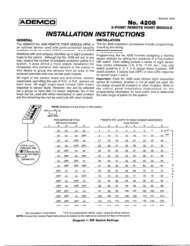
Section 4Installation Overview4.1 Model <strong>5204</strong> Wiring DiagramFigure 4-1 is a wiring diagram for wiring the various components of the Model <strong>5204</strong> panel.Any device connected to terminal 24 must be UL listed for fire use, and must be rated at12 V/24 V. Terminals 22 and 26 are the only terminals that should be used to return smokepower and should not be used for any other purpose.Figure 4-1 Model <strong>5204</strong> Wiring Diagram150644 4-1
Model <strong>5204</strong> Fire Control/Communicator Installation Manual4.2 Current Draw WorksheetDeviceNumber ofDevicesCurrent per DeviceStandbyCurrentAlarm CurrentFor each device, use this formula:This column X This column = Current per number of devices<strong>5204</strong> Fire Control/Standby: 120 mA mA1CommunicatorAlarm: 400 mA mA4180 Status Display module (2 max.)Standby: 20 mA mAAlarm: 140 mA mA5205 Dialer 1Standby : 10 mA mAAlarm: 100 mA mA5220 Direct Connect module 1Standby: 50 mA mAAlarm: 50 mA mA5230 Remote Annunciator (3 max.)Standby: 60 mA mAAlarm: 120 mA mA7181 Zone Converter (4 max.)Standby 12V/24V: 52/35 mA mAAlarm 12V/24V: 90/65 mA mAA Current Subtotals: mA mASmoke Detectors Refer to device manual for current ratings. See Tables 6-2 and 6-3 for max. # per loop.Standby: mA mAAlarm: mA mAStandby: mA mAAlarm: mA mAStandby: mA mAAlarm: mA mAB Current Subtotals: mA mANotification Devices Refer to device manual for number of devices and current ratings.Alarm: mA mAAlarm: mA mAC Current Subtotals: mA mAAdditional DevicesStandby: mA mAAlarm: mA mAStandby: mA mAAlarm: mA mAStandby: mA mAAlarm: mA mAStandby: mA mAAlarm: mA mAD Current Subtotals: mA mATotal current ratings of all devices in system (add A through D)*: mA mAE Total current ratings converted to amperes (x .001): A A* This information must be used with Table 4-1 and Table 4-2 to complete battery calculations.4-2 150644
Installation Overview4.2.1 Worksheet ExampleA worksheet is included to help you calculate the amount of current the system draws onstandby (idle) and in active (trouble or alarm) conditions. Refer to Table 4-2 to see thedifferent battery sizes available and the maximum standby current load each can support.Figure 4-2 illustrates how to complete the worksheet:Figure 4-2 Current Draw Worksheet ExampleMaximum current draw for signaling devices - 1.5 A(See Section 6.3 for additional information on signaling outputs.)Maximum Loop resistance for smoke detectors - 30 ohmsTo measure maximum loop resistance, connect an ohmmeter across the leads of a disconnectedloop.(See Table 6-2 and Table 6-3 for maximum number of smoke detectors per loop.)150644 4-3
Model <strong>5204</strong> Fire Control/Communicator Installation ManualA4.2.2 Worksheet RequirementsThe following steps must be taken when determining <strong>5204</strong> current ratings:1. For the Model <strong>5204</strong>, you must measure the alarm (active) current. If only one current ratingis listed, the draw for that device is the same whether the system is in alarm or standbycondition. The exception is for notification devices, which are rated at alarm current only.Standby current for sounding devices is 0 mA.2. To measure the maximum alarm current of the panel, measure the current draw (with nodevices connected to the panel) by connecting a DC amp meter in series with one of thebatteries. Disconnect the AC power source. Put the panel in alarm. The meter will indicatethe alarm current, which will be in the range of 120-400 mA. Fill in the system alarmcurrent in the Current per Device column on the Current Draw worksheet. You can estimatewithout measuring the alarm current by filling in the maximum total alarm current of400 mA.Note: In a 12-volt system, measure the current from both batteries (disconnect both grounds).3. For smoke detectors, notification devices and devices not mentioned in the manual, referto the device manual for the current ratings. The worksheet example shown on the previouspage provides rough estimates for a “worst case” installation.4. Use Table 4-1 to determine the battery amp hour rating needed for your installation. Referto the example (Figure 4-3) that follows. Note that the calculated rating in Row H cannotexceed the ratings shown in Table 4-2).BTable 4-1: Battery CalculationsTotal supervisory current from the Current Draw worksheet(row E).Number of standby hours (24 and 60 for NFPA 72, Chapter1, 1-5.2.5).Total Standby CurrentC Multiply Lines A and B. AHAHTotal Alarm CurrentD Total alarm current from the Current Draw worksheet (rowE).AE Alarm sounding period in hours.(For example, 5 minutes = .084 hours.)HF Multiply lines D and E. AHG Add lines C and F. AHH Multiply line G by 1.2.(Total ampere/hours required*)AH* Use next size battery with capacity greater than required.4-4 150644
Installation OverviewFigure 4-3 Battery Calculation ExampleWarning!<strong>Silent</strong> <strong>Knight</strong> does not support the use of batteries smaller than those listed in Table4-2. If you use a battery too small for your installation, the system can overload itand you may have less than the required 24 hours standby power. Use Table 4-1 tocalculate the correct battery amperes/hour rating needed for your installation.5. Refer to Table 4-2 to verify the battery size you need to provide at least the total standbycurrent you have calculated. If the installation must meet requirements for NFPA 72(Auxiliary Protected Fire Alarm Systems for Fire Alarm Service or Remote Station ProtectedFire Alarm Systems - Polarity Reversal), the total standby current cannot exceed theamount shown in the last column of the following table:RechargeableBattery SizeTable 4-2: Maximum Battery Standby LoadMax. Load for 24 hrs. Standby,5 mins. Alarm*Max. Load for 60 hrs. Standby,5 mins. Alarm17 Amp Hours 438 mA 175 mA34 AH (if wired in parallel) 875 mA 350 mA* Required for NFPA 72 Auxiliary Protected Fire Alarm systems for Fire Alarm Service (City Box) and RemoteStation Protected Fire Alarm systems (Polarity Reversal).150644 4-5
Model <strong>5204</strong> Fire Control/Communicator Installation ManualThe following formula was used to calculate the figures in Table 4-2:I = [AH ÷ H] x 0.70Where: I = Standby currentAH = Ampere-hour rating of batteryH = Standby hours0.70 = A constant used to de-rate the battery to assure a 5-year life.6. Ensure that the total alarm current you calculated, including current for the panel itself,does not exceed 3.5 A. This is the maximum alarm current allowable, whether the panelprovides 12 V or 24 V of smoke power.4-6 150644
Section 5Control Panel InstallationThe major components of the Model <strong>5204</strong> PC board are described in this section. Figure 5-1shows the <strong>5204</strong> (fuseless) printed circuit board.Figure 5-1 Model <strong>5204</strong> Board Assembly150644 5-1
Model <strong>5204</strong> Fire Control/Communicator Installation ManualCautionTo avoid the risk of electrical shock, Do NOT apply power to the Model <strong>5204</strong> until told to do so in thismanual (See Note in Section 6.2).5.1 Grounding the Model <strong>5204</strong> CoverBefore connecting power to the <strong>5204</strong>, connect the earth ground wire to the base and cover.Make sure that the ring lugs are oriented properly. The proper connection and orientation areshown in Figure 5-2. The star washers must be located between the ring lugs and the paintedsurfaces.After attaching the cover and base, make a slight bend in the wire attached to the cover. Thisis to keep it from being caught between the cover and base when the cover is closed.Figure 5-2 Connecting the Ground Wire5.2 Smoke Power SelectionWith AC power removed and batteries removed, insert the supplied jumper block (P/N130412) into P5 for 24V or P6 for 12V.5.3 Power Supply WiringA transformer is used to supply 31 VAC (220 VA) to power the system under normalconditions and to supply charging current to the backup batteries. The primary winding mustbe connected directly to the 120 VAC, 60 Hz power source (unswitched). Connect thesecondary to the <strong>5204</strong> by plugging the cable into the AC connector on the circuit board.Note: It may be necessary for a professional electrician to connect the pigtail wires on the primary winding tothe 120 VAC source.5-2 150644
Control Panel Installation5.4 Battery ConnectionNote: When using two batteries, it is recommended that they be of the same ampere hour (AH) rating and approximatelythe same age.Battery cable connectors enable installation of one or two 12 VDC, 17 A rechargeablebatteries. Two sets of battery leads are provided for battery connection. When connecting asingle battery, connect one of the red leads to the positive side of the battery. Connect a blacklead to the negative side of the battery.If using a second battery, connect the remaining lead to the positive side of the second battery.Connect the remaining black lead to the negative side of the second battery.5.5 Mounting the <strong>5204</strong>Read the environmental specifications in Section 2.2 before mounting the <strong>5204</strong> panel.The panel should be accessible to “Main Drop” wiring runs. The <strong>5204</strong> panel should bemounted as close to the center of the building as possible and located within a secured area,but should be accessible for testing and service. End-users responsible for maintaining thepanel should be able to hear alarms and troubles. When selecting a location, keep in mind thatthe panel itself is the main source of alarm and trouble annunciation.Mount the <strong>5204</strong> so it is firmly secured to the wall surface. When mounting the <strong>5204</strong> onconcrete, especially when moisture is expected, attach a piece of 3/4-inch plywood to theconcrete surface and then attach the <strong>5204</strong> to the plywood. Also mount any other desiredcomponents (such as external printer) to the plywood. If you will be flush mounting thecabinet, the hole for the enclosure should be 14 1/2” x 19 1/8” (width x length of box only).Do NOT flush-mount in a wall designated as a fire break.5.6 Terminal Strip DescriptionThe terminal strips on the PC board are nonremovable. Table 5-1 below lists the function andelectrical rating of each terminal. Note the following:• The total load of all devices attached to the system must not exceed 3.0 A.• Alarm polarity is shown for bells (terminals 7-10). Normal polarity is the opposite.• Terminals 22 and 26 are the only terminals that should be used to return smoke power, andthey should not be used for any other purpose.150644 5-3
Model <strong>5204</strong> Fire Control/Communicator Installation ManualImportant!The <strong>5204</strong> emits a hum that is not noticeable to most end users unless they are nearthe panel in a very quiet environment.TerminalNumberTable 5-1: Terminal Strip DescriptionNote: Combined smoke power maximum capacity is 1000 mA.Nominal VDC Output(“System Normal” Condition)Terminal Description12 V Mode 24 V Mode1* Auxiliary Power (+) - 1500 mA max. 13.65 27.32* Ground 0 03* Annunciator Power (+) - 500 mA max. 13.5 13.64* Serial Annunciator Data Out (SKO) 9.1 9.25* Serial Annunciator Data In (SKI) 6.6 6.76* External Silence Switch or Alarm Reset 8.6 8.67 Bell 1 - 1500 mA max. 5.0 10.08 Bell 1 + 0.95 1.99 Bell 2 - 1500 mA max. 5.0 10.010 Bell 2 + 0.95 1.911 Relay 1 Normally Open N/A N/A12 Relay 1 Common N/A N/A13 Relay 1 Normally Closed N/A N/A14 Relay 2 Normally Open N/A N/A15 Relay 2 Common N/A N/A16 Relay 2 Normally Closed N/A N/A17* Auxiliary Power - 175 mA 13.64 13.7718* Zone 1 (Class B/Style B) Input 0.08 0.1619* Smoke Power 13.65 27.320* Zone 2 (Class B/Style B) Input 0.08 0.1621* Smoke Power 13.65 27.322* Ground 0 023* Zone 3 (Class B/Style B) Input 0.08 0.1624* Smoke Power 13.65 27.325* Zone 4 (Class B/Style B) Input 0.08 0.1626* Ground 0 0* Power-limited5-4 150644
Control Panel Installation5.7 Model 5205 Dialer and Telephone LineConnection (Optional)The Model 5205 Dialer Module enables the <strong>5204</strong> to function as a communicator panel andprovides the following features:• Optional two-number dialing with same or different account codes and reporting formats.Alarms, troubles, disables, and tests can be programmed to report to either or both numbers.• Programmable as rotary-only or as rotary/Touch-Tone dialing.• Ring Detect feature on line 1 for downloading data to panel from a remote computer site.• Transient voltage protection of phone lines.• Automatic daily test (programmable from Model 5230 annunciator, built-in touchpad, orremote site via downloading option).• Optional ground start operation (not for use on UL systems).• Compatibility with the following UL fire listed receivers:ReceiverFormats it will Receive<strong>Silent</strong> <strong>Knight</strong> Model 9000 All formats listed in Section 10Osborn & Hoffman Quickalert All formats listed in Section 10Ademco 685All tone burst formats (3/1 1400 Hz)FBI CP2203/1 and 4 + 2 formatsRadionics D6500BFSK 1400/2300 formatsInstallationTo meet NFPA 72 Central Station Fire Alarm Systems requirements, both telephone linesmust be installed.Connect the 5205 to the phone line using an RJ31X type phone jack. The telephone companywill install an RJ31X jack upon request.The 5205 comes with stand-offs that you can place into the four holes just left of the built-intouchpad on the <strong>5204</strong> panel. To connect the 5205 to the <strong>5204</strong>, make sure the dialer connector150644 5-5
Model <strong>5204</strong> Fire Control/Communicator Installation Manualpins are positioned correctly before pressing the 5205 onto the stand-offs.Figure 5-3 Model 5205 Dialer/Telephone ConnectionRing Detect CircuitIf the installing company calls the <strong>5204</strong> to up- or download data to or from a remote computer,the built-in ring detect circuit on line 2 will detect the ring. After the programmed number ofrings (Step 55 in Section 8), it seizes the line and allows the transfer of data.The <strong>5204</strong> has built-in dual phone line monitors. These circuits will detect any fault in thephone lines by monitoring the DC voltage present on the lines. They feature a delay ofapproximately 40-90 seconds before a line fault is reported as a trouble. When a fault isdetected, the audible trouble signal will sound and the trouble will be reported to the centralstation over the remaining phone line.A situation could occur where both phone lines appear to be good, but the dialer cannot getthrough to the central station on the first line. In this case, the <strong>5204</strong> will switch phone linesand attempt the call again using the second line.Note: To comply with industry standards, this product is equipped with line seizure. Any time the system’s dialerneeds to communicate with the central station, it will not be possible to use any telephones that are on thesame line(s) as the fire system. Normally, this condition will last approximately one minute, but under adversetelephone circuit conditions, could last for as long as 15 minutes.5-6 150644
Control Panel Installation5.8 Cable ConnectorsStatus (P1)Connects the Model 4180 display model to the <strong>5204</strong>.Model 5230 (P2)Can be used to temporarily connect the Model 5230 Remote Annunciator to the <strong>5204</strong> forprogramming or troubleshooting.Note: A quick connect program cable (P/N 130294) can be ordered separately for this connection.Warning!Do NOT use connector P2 for permanent installation. If the annunciator is to beinstalled permanently, it MUST be wired to the <strong>5204</strong> terminal block (see SectionWiring the 5230 Remote Annunciator).Power Supply (AC) Connector (P4)Connects the <strong>5204</strong> control panel to the power supply.150644 5-7
Model <strong>5204</strong> Fire Control/Communicator Installation Manual5-8 150644
Compatible Product Installation6.1.2 Two-Wire Smoke Detector ConnectionFigure 6-3 shows how to connect two-wire smoke detectors to class B (style B) zones.Figure 6-3 Two-Wire Smoke Detector WiringTable 6-1 and show the two-wire smoke detectors that are approved for use with the <strong>5204</strong>.Notes for Both Tables1. If a separate base is used with a detector, the model number is shown in parentheses in theModel column.2. In the Type column, I = Ionization, P = Photoelectric, D = Duct3. ID = Detector (Base) Identifiers4. Control unit Smoke Reset Time must be programmed for a number greater than or equalto the maximum reset time of the smoke detector (last column of chart).5. The maximum number of smoke detectors per zone is determined by both the currentdraw and the impedance of the smoke detector. If too many smoke detectors are used onany zone, false alarms could occur.6. If different models of detectors are mixed on a zone, false alarms could occur.150644 6-3
Model <strong>5204</strong> Fire Control/Communicator Installation ManualNote: The <strong>5204</strong> contains a programmable smoke reset time. Be sure to program the panel to meet the reset timeof the detectors.DetectionSystemsESLTable 6-2: Compatible 12-Volt Smoke DetectorsVoltage range: 9.5 VDC - 14 VDC: Identifier: 12CManuf. Model Type *IDSystem Sensor<strong>5204</strong> (Max.per Loop)SmokeDet.Reset TimeDS200 (MB200-2W) P D 15 1 sec.DS200HD (MB200-2W) P D 15 1 sec.DS250 (MB2W or MB2WL) P B (A) 11 1 sec.DS250TH (MB2W or MB2WL) P B (A) 11 1 sec.DS250HD (MB2W or MB2WL) P B (A) 11 1 sec.425C P S10 20 1 sec.425CT P S10 20 1 sec.425CR P S10 20 1 sec.425CRT P S10 20 1 sec.429C (S10A) P S10A 12 1 sec.429CT (S10A) P S10A 12 1 sec.429CRT (S11A) P S11A 12 1 sec.429CST (S11A) P S11A 12 1 sec.611U (601U) P S10 (S00) 24 1 sec.611UD (601U) D S10 (S00) 24 1 sec.611UT (610U) P S10 (S00) 24 1 sec.612U (601U) I S10 (S00) 24 1 sec.612U (601U) D S10 (S00) 24 1 sec.612UD (601U) P S10 (S03) 24 1 sec.611U (602U) D S10 (S03) 24 1 sec.611UD (602U) P S10 (S03) 24 1 sec.611UT (602U) I S10 (S03) 24 1 sec.612UD (602U) D S10 (S03) 24 1 sec.1451 (B401B) I A 10 6 sec.1800 I A 12 0.9 sec.1851B (B101B) ID A 10 2 sec.1851DH (DH1851DC) ID A 10 2 sec.2151 (B110LP) P A 10 .3 sec.2400 P A 10 6 sec.2400 (DH400) P A 10 1 sec.2400TH P A 10 6 sec.2451 (B401B) P A 10 1 sec.2451TH (B401B) P A 10 6 sec.2800 P A 10 6 sec.2800TH P A 10 6 sec.2851B (B101B) PD A 10 2 sec.2851TH (B101B) PD A 10 2 sec.2851DH (DH2851DC)I PD A 10 2 sec.6-4 150644
Compatible Product InstallationNote: Note: The <strong>5204</strong> contains a programmable smoke reset time. Be sure to program the panel to meet the resettime of the detectors.ApolloTable 6-3: Compatible 24-Volt Smoke DetectorsVoltage range: 9.5 VDC - 14 VDC: Identifier: 12CManuf. Model Type *IDSystem SensorDetectionSystemsESL<strong>5204</strong> (Max.per Loop)Smoke Det.Rest Time55000-250 (45681-200) I 55000-250 (45681-200) 24 1 sec.55000-350 (45681-200) P 55000-350 (45681-200) 12 1 sec.1451 (B401B) I A 12 6 sec.1800 I A 12 0.9 sec.1851B (B101B) ID A 12 2 sec.1851DH (DH1851DC) ID A 12 2 sec.2151 (B110LP) P A 12 .3 sec.2400 P A 12 6 sec.2400 (DH400) P A 12 1 sec.2400TH P A 12 6 sec.2451 (B401B) P A 12 1 sec.2451TH (B401B) P A 12 6 sec.2800 P A 12 6 sec.2800TH P A 12 6 sec.2851B (B101B) PD A 12 2 sec.2851TH (B101B) PD A 12 2 sec.2851DH (DH2851DC)I PD A 12 2 sec.DS200 (MB200-2W) P D 24 1 sec.DS200HD (MB200-2W) P D 24 1 sec.425 P S10 30 1 sec.425CT P S10 30 1 sec.429C (S10A) P S10A 14 1 sec.429CT (S10A) P S10A 14 1 sec.429CRT (S11A) P S11A 14 1 sec.429CST (S11A) P S11A 14 1 sec.611U (601U) P S10 (S00) 30 1 sec.611UD (601U) D S10 (S00) 30 1 sec.611UT (610U) P S10 (S00) 30 1 sec.612U (601U) I S10 (S00) 30 1 sec.612U (601U) D S10 (S00) 30 1 sec.612UD (601U) D S10 (S03) 30 1 sec.611UD (602U) P S10 (S03) 30 1 sec.611UT (602U) I S10 (S03) 30 1 sec.612UD (602U) D S10 (S03) 30 1 sec.Gentex 224 P -25-1 16 6 sec.SLK-24F (HS-224D) P HD-3 (HB-5) 20 0.1 sec.HochikiSLK-24FH (HS-224D) P HD-3 (HB-5) 20 0.1 sec.150644 6-5
Model <strong>5204</strong> Fire Control/Communicator Installation Manual6.2 Connections to Compatible <strong>Silent</strong> <strong>Knight</strong>ProductsThis section describes the connections of the following <strong>Silent</strong> <strong>Knight</strong> products:·• Model 4180 Status Display Module (see Section 6.2.1)• Model 5220 Direct Connect Module (see Section 6.2.2)• Model 5230 Remote Annunciator (see Section 6.2.3)• Model 5395 Distributed Power Module (see Section 6.2.4)• Model 5205 Dialer Module (see Section 5.7)• Model 7181 Zone Converter (see Section 6.2.5)Note: Once you have installed the <strong>5204</strong> and, if applicable, the 5230 and the 4180, test the basic system. Applypower, test the touchpad, then remove the power. Wire each auxiliary device with the power off. After youinstall each device, test it by re-applying the power. When you power up the <strong>5204</strong>, the two dots on the builtintouchpad display will alternately flash on and off.Note also that there is a 2-second power-up delay on the 5230.6.2.1 Model 4180 Status Display ModuleThe Model 4180 Status Display module provides remote annunciation of alarm and troublestatus information for each zone.The 4180 has 2 connectors, each of which has 8 outputs available for annunciation. Theseoutputs are active high at +12 VDC. Each output can provide up to 100 mA of current, with atotal limitation of 175 mA (when used with the <strong>5204</strong>). The module has 4 normally openrelays that are nondedicated, and therefore can be wired to be active with any of the outputs.The 4180 is not supervised. Table 6-4 shows the system status indicated by each LED.Do not use the 4180 relays in a 12 V <strong>5204</strong> installation.Table 6-4: Model 4180 ConnectionConnector P2 System Status Connector P3 System Status1 Alarm 1 1 Line #1 Trouble2 Alarm 2 2 Line #2 Trouble3 Alarm 3 3 Bell #1 Trouble4 Alarm 4 4 Bell #1 Trouble5 Trouble 1 5 Battery Trouble6 Trouble 2 6 AC Trouble7 Trouble 3 7 Silence Trouble8 Trouble 4 8 Dialer TroubleThe 4180 can be used to interface to long-range RF systems.6-6 150644
Compatible Product InstallationFigure 6-4 Model 4180 ConnectionWhen using a 4180, maintain a physical separation of one-half inch or more between fieldwires and connection points to prevent damage from transients.6.2.2 Model 5220 Direct Connect ModuleThe 5220 Direct Connect Module can be used with the <strong>5204</strong> to meet NFPA 72 RemoteSignaling or Local Protective Signaling standards. The 5220 requires four connections to the<strong>5204</strong> and provides outputs for direct connect (city box) and polarity reversal.To meet the 60-hour standby power requirements for NFPA 72 systems, normal standbycurrents are de-rated. See Section 4.2 for these current values.150644 6-7
Model <strong>5204</strong> Fire Control/Communicator Installation Manual6.2.2.1 InstallationLocate the knockout on the right side of the <strong>5204</strong> cabinet to connect the 5220 using a shortpiece of conduit (must not exceed 20 feet in length).A four-wire pigtail is provided to wire the 5220 to the <strong>5204</strong>. Figure 6-5 shows how to wirethe Model 5220 Direct Connect module. The wiring chart uses bell #2 as the initiating loop.Program bell #2 to be active for the events to be reported.Figure 6-5 Model 5220 Wiring Diagram6.2.2.2 City Box Connect (24 VDC Systems Only)(For NFPA 72 Auxiliary Protected Fire Alarm systems for fire alarm service.)With the 5220, you can connect the <strong>5204</strong> directly to a municipal fire alarm box or "city box."The city (master) box is an enclosure that contains a manually operated transmitter used tosend an alarm to the municipal communication center, which houses the central operating partof the fire alarm system. To ensure communication of an active alarm status, use the 5220only with <strong>5204</strong> 24 V systems when connected to a series type DC master box.Wire the 5220 to the <strong>5204</strong> as shown in Figure 6-5. Wire the city box coil to terminals 3 and 4in the 5220. Maximum coil and wire resistance (combined) is 30 ohms.It is not possible to reset the remote indication until you clear the condition and reset the <strong>5204</strong>panel.Select relay 2 for 5220 city box. When you select 5220 operation, bell 2 and relay 2 cannot beused for any other purpose.Any zone programmed to activate bell 2 will cause an alarm to be sent.6-8 150644
Compatible Product Installation6.2.2.3 NFPA 72 Polarity Reversal (12 or 24 VDC Systems)The 5220 provides a current that reverses polarity during an alarm or removes current during atrouble condition.Wire the 5220 for polarity reversal as shown in Figure 6-6.Figure 6-6 Wiring the 5220 for Polarity ReversalAlarms will override trouble conditions, and it will not be possible to reset the remoteindication until you clear the condition and reset the <strong>5204</strong> panel.Select relay 2 for 5220 Direct Connect. When you select 5220 operation, bell 2 and relay 2cannot be used for any other purpose.Any trouble condition will cause a trouble to be sent. Any zone programmed to activate bell 2will cause an alarm to be sent.6.2.3 Model 5230 Remote AnnunciatorThe Model 5230 Remote Annunciator is an optional touchpad (keystation) you can use forEnglish-language programming. The 5230 also provides trouble and alarm information.When programming the <strong>5204</strong>, be sure to select the correct number of supervised annunciators(see Section 8.4.3).6.2.3.1 Setting ID CodesBefore permanently installing the Model 5230 Remote Annunciator, you must first set itsidentification codes. Each annunciator to be supervised must be given its own identificationcodes. The ID numbers must start at 1 and progress sequentially to 3 (3 annunciators max.).Upon initial power up, the address of each annunciator is displayed.150644 6-9
Model <strong>5204</strong> Fire Control/Communicator Installation ManualOn the back of each annunciator is a small 4-position dip switch you can use to set the IDcode. Table 6-5 shows the positions (up or down) of the various switches for specific IDcodes.Table 6-5: Model 5230 Dip Switch SettingsID NumberSwitches1 2 3 40 * Up Up Up Up1 Down Up Up Up2 Up Down Up Up3 Down Down Up Up* Not Supervised6.2.3.2 Wiring the 5230 Remote AnnunciatorA 4-position terminal block is provided with the Model 5230 Annunciators to connect them tothe <strong>5204</strong>. Figure 6-7 shows the wiring for the Model 5230.Figure 6-7 Model 5230 Connection6-10 150644
Compatible Product Installation6.2.3.3 Mounting the 5230 Remote AnnunciatorFor UL installations, the 5230 Remote Annunciators must be mounted on a dual gangelectrical box.To mount the annunciator, you must first remove the rear mounting plate.To do this, insert a #4 flat blade screwdriver into the slots located on the bottom edge of theannunciator. Gently turn the screwdriver until the mounting plate pulls away from the frame.Once you remove the mounting plate, you can secure it to the wall using #6 or #8 screws. Themounting plate should be oriented so that the word TOP is toward the top of the plate andfacing you. Through the square hole in the mounting plate, run the wiring to the annunciator.When all of the wires are connected to the annunciator, set the top of the annunciator over thetabs on the top of the mounting plate. Make sure the wires are not pinched between the frameand the mounting plate. Press each corner of the bottom side onto the annunciator mountingplate until you hear it click into place.Note: You may have to gently squeeze the annunciator (top to bottom) to align it while snapping the bottom edgeinto place.6.2.4 Model 5395 Distibuted Power ModuleFigure 6-8 shows you how to connect the Model 5395 to the Model <strong>5204</strong> panel.Figure 6-8 Model 5295 Connection150644 6-11
Model <strong>5204</strong> Fire Control/Communicator Installation Manual6.2.5 Model 7181 Zone ConverterThe Model 7181 Zone Converter adapts the <strong>5204</strong> class B (style B) zones so that they can beconnected to class A (style D) initiating devices. Figure 6-9 shows a typical installation.Refer to the Model 7181 Installation Manual (P/N 150632) for further information.Figure 6-9 Connecting Class B (Style B) Sensor to Class A (Style D) Panel (24 V)6-12 150644
Compatible Product Installation6.3 Supervised Notification Device OutputsNote: To reduce the possibility of false alarms and transient damage, DO NOT bundle telephone wires togetherwith notification device or zone wires.The <strong>5204</strong> provides two supervised notification device outputs to annunciate alarm conditions.These outputs can be programmed for each individual zone. For proper operation, you mustuse polarized notification devices with a model 7628 4.7K ohm end-of-line (EOL) resistor oneach loop. See Figure 6-10 for connection to the <strong>5204</strong> panel.Figure 6-10 Model <strong>5204</strong> Notification Device ConnectionsThe UL listed sounding appliances that can be used with the <strong>5204</strong> are listed in Table 6-6 andTable 6-7.Table 6-6: Compatible 12-Volt Notification DevicesManufacturer Model Number Device TypeFederal SignalGentexWheelockVALSStrobe450-D HornHG124HornSHG12LHorn StrobeSHG12HHorn Strobe34T-12-RAlarm Horn462-G10-12-RBell7001T-12-RMini-Horn7001T-12-WMini-Horn7001T-12W-FRStrobe Horn7002T-12-W-FRStrobe HornMB-G6-12-RMotor BellMB-G10-12-RMotor BellMBS-G6-12-W-HF-RMotor Bell with StrobeMBS-G10-12-W-HF-RMotor Bell with StrobeMIZ-12-RMini-HornMIZ-12-WMini-HornMIZ-12-WS-VF-RMini-Horn/StrobeMT-12/24-RStrobe HornV7001T-W-FRStrobe HornWST-12-FRStrobeWS1T-12-FRStrobeWS3T-12-FRStrobe150644 6-13
Model <strong>5204</strong> Fire Control/Communicator Installation ManualTable 6-7: Compatible 24-Volt Notification DevicesManufacturer Model Number Device TypeFaraday446X 12/24VDCVibrating Bell476X 12/24VDCVibrating Bell477X 12/24VDCSingle Stroke Bell5303B-0-14-( )-DCChime (flush)5304B-0-14-( )-DCChime (surface)5305B-0-4-( )-DCChime (ceiling)5306B-0-14-( )-24-DCChime/Strobe (flush)5307B-0-14-( )-24-DCChime/Strobe (surface)5308B-0-4-( )-24-DCChime/Strobe (ceiling)5333B-0-14-24-DCMulti-Tone Horn (flush)5334B-0-14-24-DCMulti-Tone Horn (surface)5336B-( )-14-24-DCMulti-Tone Horn/Strobe (flush)5337B-( )-14-24-DCMulti-Tone Horn/Strobe (surface)5338B-( )-4-24-DCMulti-Tone Horn/Strobe (ceiling)5343B-0-14-24-DCSingle Tone Horn/Strobe (flush)5344B-0-14-24-DCSingle Tone Horn/Strobe (surface)5345B-0-4-24-DCSingle Tone Horn/Strobe (ceiling)5348B-( )-4-24-DCSingle Tone Horn/Strobe (ceiling)5373B-0-14-(12 or 24)-DC 8-Tone Horn/Strobe (flush)5374B-0-14-(12 or 24)-DC 8-Tone Horn/Strobe (surface)5375B-0-4-(12 or 24)-DC 8-Tone Horn/Strobe (ceiling)5376B-0-14-24-DC8-Tone Horn/Strobe (flush)5377B-0-14-24-DC8-Tone Horn/Strobe (surface)5378B-0-4-24-DC 8-Tone Horn/Strobe (ceiling)5405B-0-14-24-DCSync Control Unit5508B-( )-14-24-DCSingle Gang Sync Strobe (flush)5521B-( )-14-24-DC4” Square Sync Strobe (surface)5522B-( )-14-24-DC4” Square Sync Strobe (flush)6126B-U-14-24 VDCHorn/Strobe6223B-0-14-24-DCHorn (flush)6224B-0-14-24-DCHorn (surface)6225B-0-4-24-DCHorn (ceiling)6226B-( )-14-24-DCHorn/Strobe (flush)6227B-( )-14-24-DCHorn/Strobe (surface)6-14 150644
Compatible Product InstallationTable 6-7: Compatible 24-Volt Notification DevicesManufacturer Model Number Device TypeFaraday (continued)Federal SignalGentex6228B-( )-4-24-DC6243B-0-14-24-DC6244B-0-14-24-DC6245B-0-4-24-DC6246B-( )-14-24-DC6247B-( )-14-24-DC6248B-( )-4-24-DC6300B-0-14-24-DC6301B-0-14-24-DC6302B-( )-4-24-DC6310B-0-14-24-DC6311B-0-14-24-DC6312B-( )-14-24-DC6320B-0-14-24-DC6321B-0-14-24-DC6322B-( )-14-24-DC450 HornVALSHorn/StrobeGX90-4HornGXS-4-15-1StrobeGXS-4-1575StrobeGX90S-4-15HornGX90S-4-1575HornHG124HornSHG24-1575Horn/StrobeSHG24-15Horn/StrobeGMH-24-XHornGMS-24-XHorn/StrobeGMS-24-XHorn/StrobeG0T24HornG0S24-XHornWGMS-24-XHorn/StrobeHorn/Strobe (ceiling)Electron-Mechanical Horn (flush)Electron-Mechanical Horn (surface)Electron-Mechanical Horn (ceiling)Electron-Mechanical Horn/Strobe(flush)Electron-Mechanical Horn/Strobe(surface)Electron-Mechanical Horn/Strobe(ceiling)Mini-Horn (flush)Mini-Horn (surface)Mini-Horn (ceiling)Mini-Horn/Strobe/Strobe (flush)Mini-Horn/Strobe/Strobe (surface)Mini-Horn/Strobe/Strobe (ceiling)Sync Mini Horn/Strobe (1 gang)Sync Mini Horn/Strobe (1,2 gang)Mini Horn/Sync Strobe (1,2 gang,4SQ)150644 6-15
Model <strong>5204</strong> Fire Control/Communicator Installation ManualTable 6-7: Compatible 24-Volt Notification DevicesManufacturer Model Number Device TypeSystem SensorWheelockMASS241Horn/StrobeMASS24110ADA Horn/StrobeMASS2415ADAHorn/StrobeMASS2475ADAHorn/StrobeSS1215ADAStrobeSS4110ADAStrobeSS2415ADAStrobeSS2475ADAStrobePS2415ADAMini-Horn/StrobePS241575ADAMini-Horn/StrobePS24110ADAMini-Horn/StrobePS2475ADAMini-Horn/Strobe46T-G4-24-RBell46T-G6-24-RBell46T-G10-24-RBell46T-G6-24-WS-24-HF-R Strobe/Bell46T-G10-24-WS-24-HF-R Strobe/Bell46T-G6-24-WH-24-HF-R Strobe/Bell46T-G10-24-WH-24-HF-R Strobe/Bell7001T-12\24-W-FRStrobe Horn7002T-12\24-W-FRStrobe HornAES-DL1-RMultitone HornAES-EL1-RMultitone HornAES-DL1-WS-24-VF-R Multitone HornAES-EL1-WS-24-VF-R Multitone HornAES-DL1-WH-24-VF-R Multitone HornAES-EL1-WH-24-VF-R Multitone HornAES-DL1-WM-24-VF-R Multitone HornAES-EL1-WM-24-VF-R Multitone HornAH-24-R HornAMT-12\24-RStrobe HornAMT-24-LS-VFRStrobe HornAMT-24-LSM-VFRStrobe HornAMT-24-IS-VFRStrobe HornAS-2415-VFRStrobe HornAS-241575-VFRStrobe Horn6-16 150644
Compatible Product InstallationTable 6-7: Compatible 24-Volt Notification DevicesManufacturer Model Number Device TypeWheelock (cont.)AS-2430-VFRAS-2475-VFRAS-24110-HFRSM-12\24-RDSM-12\24-RCF-BF1CF-BF1-RCH-CF1CH-CF1-RCH-CF1-WCH-DF1CH-DF1-RCH-BF1-WS-24-HF-RCH-CF1-LS-24CH-CF1-MS-24CH-CF1-IS-24CH-CF1-LS-24-CFWCH-CF1-MS-24-CFWCH-CF1-IS-24-CFWCH-CF1-WS-24-CF-WCH-DF1-LS-24CH-DF1-MS-24CH-DF1-IS-24CH-DF1-LS-24-VFRCH-DF1-LSM-24-VFRCH-DF1-MS-24-VFRCH-DF1-IS-24-VFRCH-DF1-WM-24-VFRCH-DF1-WS-24-VF-RDSM-12/24EH-DL1-REH-EL1-R Electronic HornEHS-DL1-W-VF-REHS-EL1-W-VF-REH-DL1-WS-24-VF-REH-EL1-WS-24-VF-RStrobe HornStrobe HornStrobe HornStrobe Horn ControllerStrobe Horn ControllerChimeChimeChimeChimeChimeChimeChimeStrobe ChimeStrobe ChimeStrobe ChimeStrobe ChimeStrobe ChimeStrobe ChimeStrobe ChimeStrobe ChimeStrobe ChimeStrobe ChimeStrobe ChimeStrobe ChimeStrobe ChimeStrobe ChimeStrobe ChimeStrobe ChimeStrobe ChimeSync ModuleElectronic HornElectronic HornStrobe Horn (single input)Strobe Horn (single input)Strobe Horn (dual input)Strobe Horn (dual input)150644 6-17
Model <strong>5204</strong> Fire Control/Communicator Installation ManualTable 6-7: Compatible 24-Volt Notification DevicesManufacturer Model Number Device TypeWheelock (cont.)EH-DL1-WH-24-VF-REH-EL1-WH-24-VF-REH-DL1-WM-24-VF-REH-EL1-WM-24-VF-RHSW-24-HFRHS2W-24-HFRHSPW-24-HFRIS-24-VFRIS1-24-VFRIS3-24-VFRISP-24-HFRLS-24-VFRLS1-24-VFRLS3-24-VFRLSP-24-HFRLSM-24-VFRLS1M-24-VFRLS3M-24-VFRLSPM-24-VFRMS-24-VFRMS1-24-VFRMS3-24-VFRMSP-24-HFRMB-G6-24-RMB-G10-24-RMBS-G6-24-W-HF-RMBS-G10-24-W-HF-RMIZ-24-RMIZ-24-WMIZ-24-LS-VFRMIZ-24-LSM-VFRMIZ-24-MS-VFRMIZ-24-HSW-HFRMIZ-24-IS-VFRMIZ-24-WS-VF-RMIZ-24-WS-VF-WStrobe Horn (dual input)Strobe Horn (dual input)Strobe Horn (dual input)Strobe Horn (dual input)Remote StrobeRemote StrobeRemote StrobeRemote StrobeRemote StrobeRemote StrobeRemote StrobeRemote StrobeRemote StrobeRemote StrobeRemote StrobeRemote StrobeRemote StrobeRemote StrobeRemote StrobeRemote StrobeRemote StrobeRemote StrobeRemote StrobeMotor BellMotor BellMotor Bell with StrobeMotor Bell with StrobeMini-HornMini-HornMini-Horn/StrobeMini-Horn/StrobeMini-Horn/StrobeMini-Horn/StrobeMini-Horn/StrobeMini-Horn/StrobeMini-Horn/Strobe6-18 150644
Compatible Product InstallationTable 6-7: Compatible 24-Volt Notification DevicesManufacturer Model Number Device TypeWheelock (cont.)MIZ-24-WH-VF-WMIZ-24-WM-VF-WMT-12/24-RMT-24-LS-VFRMT-24-LSM-VFRMT-24-MS-VFRMT-24-IS-VFRMT-24-SL-VFRMT-24-SLM-VFRMT-24-WMMT-24-WM-VF-RMT-24-WM-VFRRS-2415-HFRRSP-2415-VFRRS-241575-VFRRSP-241575-VFRRS-2430-VFRRS-2430-HFRRS-2475-VFRRSP-2475-HFRRS-24110-HFRRSP-24110-HFRSL-24-VFRSL1-24-VFRSL3-24-VFRSLP-24-VFRSLM-24-VFRSL1M-24-VFRSL3M-24-VFRSLPM-24-VFRSHW-24-VFRSH2W-24-VFRSHPW-24-VFRSCM-24-RSM-12/24-RSR-2415-VFRMini-Horn/StrobeMini-Horn/StrobeStrobe HornStrobe HornStrobe HornStrobe HornStrobe HornStrobe HornSynch. Multitone StrobeStrobeHornHornStrobeStrobeStrobeStrobeStrobeStrobeStrobeStrobeStrobeStrobeSynchronized Remote StrobeSynchronized Remote StrobeSynchronized Remote StrobeSynchronized Remote StrobeSynchronized Remote StrobeSynchronized Remote StrobeSynchronized Remote StrobeSynchronized Remote StrobeSynchronized Remote StrobeSynchronized Remote StrobeSynchronized Remote StrobeController for Synchronized StrobesSync ModuleSync Strobe150644 6-19
Model <strong>5204</strong> Fire Control/Communicator Installation ManualTable 6-7: Compatible 24-Volt Notification DevicesManufacturer Model Number Device TypeWheelock (cont.)SRP-2415-HFRSR-241575-VFRSRP-241575-VFRSR-2475-VFRSR-2475-HFRSR-24110-HFRSRP-24110-HFRV7001T-12\24-W-FRWM3T-24-FRWM3T-24-VFRWS1T-24-FRWS3T-24-FRWST-24-FRSync StrobeSync StrobeSync StrobeSync StrobeSync StrobeSync StrobeSync StrobeStrobe HornRemote StrobeRemote StrobeStrobeStrobeStrobe6.4 Auxiliary RelaysThe <strong>5204</strong> provides two auxiliary relay outputs. Relay #2 output annunciates fire alarms.Relay #2 can be programmed to annunciate either alarm or trouble conditions, or can be usedto activate the Model 5220 Direct Connect Module. Figure 6-11 shows the relay contactconnections.)• Fire alarm• The Model 5220 Direct Connect Module (see Section 6.2.2).• Trouble Conditions (any system trbl.)6-20 150644
Compatible Product InstallationFigure 6-11 Auxiliary Relays6.5 External Silence Keyswitch (Optional)For manual silencing or resetting alarms, you can attach a remote keyswitch to the <strong>5204</strong> atterminal #6. Use a UL listed keyswitch. The keyswitch will operate as Normally OpenMomentary at 24 VDC/.25 A minimum.Once the keyswitch has been wired, it must be programmed either to silence or reset alarms(see Section 8.4.1.). If programmed to silence, the keyswitch turns off an annunciator that issignaling a trouble or alarm condition.If programmed to reset alarms, the keyswitch removes smoke detector power for aprogrammed length of time (see Section 8.4.1). This allows the smoke detector to sense newalarm conditions.Figure 6-12 Wiring an External Silence or Reset Alarms KeyswitchThe external keyswitch silences notification devices and horns only, not the onboard beeper orlocal annunciators. See Section 7.1.3 if you need additional information.If using a pushbutton reset, it must be placed within a firefighter’s lockbox.150644 6-21
Model <strong>5204</strong> Fire Control/Communicator Installation Manual6-22 150644
Section 7Normal OperationThe optional Model 5230 Remote Annunciator provides annunciation of trouble and alarmconditions, and can be used to program the system. Key functions for both the Model 5230(Figure 7-1) and the <strong>5204</strong> built-in touchpad (Figure 7-2) are described in Section 7.1. Section8 explains how to program the <strong>5204</strong> using the Model 5230.Figure 7-1 Model 5230 Remote AnnunciatorThe Model 5230 Remote Annunciator has a liquid crystal display (LCD) for displayingEnglish-language messages. If the <strong>5204</strong> is not being programmed, the LCD cycles through allmessages that are applicable at the time, showing a different one every 1.5 seconds. Refer toSection 9.3 for more information on troubleshooting messages.When AC power is being supplied, and the battery is fully charged, the POWER LED glowssteadily. If the POWER LED is flashing, the AC power has been removed or the backupbattery is low. If neither AC nor battery power is being supplied, the POWER LED is off.The audio transducer buzzer produces short beeps to annunciate keystrokes. It also emits along, high-pitched tone to denote a trouble condition or to indicate that an annunciatorfunction has been entered incorrectly (see Section 7.1).150644 7-1
Model <strong>5204</strong> Fire Control/Communicator Installation ManualFigure 7-2 Built-in Touchpad7.1 Built-in Touchpad and Model 5230 AnnunciatorOperationTo operate the <strong>5204</strong>, you must use either the built-in touchpad or the Model 5230 RemoteAnnunciator. This annunciator functions the same as the internal touchpad except for theSTEP key. The installer uses this key to step through programming options (see Section 8.3).Following are the basic operating functions. Note that if no keys are pressed for 15 minuteswhile in program mode, the system will time out and resume normal operation.The message TRY AGAIN appears on the 5230 display if you do not press any keys for 5seconds while accessing a function, or, if you attempt to access a function before exiting fromanother function.In the following table, Code 0 refers to the installer’s code (factory programmed as <strong>5204</strong>).Code 1 refers to the operator’s code (factory programmed as 1111). These two codes aredescribed in Step 45 and Step 46 of Step Programming (see Section 8.4.1).7-2 150644
Normal OperationNote: A valid operating code is always required when using the 5230.Table 7-1: Touchpad OperationsTo:Press:5230 Annunciator Built-in TouchpadAdditional InformationClearTest the systemReset alarms(or smokedetectors)+ code 0 or 1+ code 0 or 1 1 + code 0 or 1Enables you to start again if youenter the wrong keystrokes. If youenter a function incorrectly on the5230, the annunciator’s PZTbuzzer will emit a long, highpitchedtone.The system will test the 4180outputs, the built-in touchpad LEDdisplay, signaling devices, sirens,and communicator.After a smoke alarm has beentriggered, this function removessmoke detector power for theprogrammed length of time (asdetermined by the smokedetector). This allows the smokedetector to sense new alarmconditions.When a trouble condition occurs and you reset the alarm, the trouble condition is stored in memory until you clear the alarmmemory. If you do not clear the alarm memory, the trouble condition is displayed the next time a trouble condition occurs,implying incorrectly that more than one trouble condition exists.Clear alarmmemoryReset the dialerInitiate downloadDisplay alarmmemoryDisplay troublesSilence troubleor alarm conditionsCLEARTEST0RESETALARM1CLEARMEMORY2DIAL.RESET3LOAD4DISPLAYMEMORY5DISPLAYTRBL.6SILENCESTEPENTERENTERENTERENTERENTERENTERENTER+ code 0 or 1+ code 0 3 + code 0+ code 0 4 + code 0+ code 0 or 1+ code 0 or 1+ code 0 or 1CLEARTEST ENTER0RESETALARM ENTERCLEARMEMORY ENTER2DIAL.RESET ENTERLOADENTERDISPLAYMEMORY ENTER5DISPLAYTRBL. ENTER6SILENCEClears all data out of alarmmemory and resets the 4180.(This function removes allmemory of alarms.)Aborts an in-progress call to thecentral station.Starts the downloading process.Exit the DOWNLOADING modeby pressing CLEAR CLEAR.Displays the current alarmmemory. (It is recommended thatyou clear alarm memory afterdisplaying it.)Displays trouble conditions.Silences signaling devices thatare in trouble or alarm. (Onboardbeeper and local annunciatorscontinue to sound untilserviced. See Section 9.1 formore details.)150644 7-3
Model <strong>5204</strong> Fire Control/Communicator Installation ManualTable 7-1: Touchpad OperationsFire drillSet timeTo:CLEARMEMORY2code 0 or 1To end a fire drill:++ code 0 or 1Press:5230 Annunciator Built-in TouchpadTEST0SILENCESTEPSETTIME9ENTERENTERCLEARMEMORYTEST ENTER02+ code 0To end a fire drill:SILENCESETTIME ENTER9Additional InformationCauses the system to sound analarm and report a FIRE TEST.Enter time in military time..The SET MODE LED will turn on and the built-in touchpad display will flash 9- indicating that you are in theSET TIME mode.Note: The <strong>5204</strong> powers up in the SET TIME mode, with 9- showing on the display. If you wish to set thetime at this point, it is not necessary to press the 9 ENTER (code) key sequence. Simply key in the appropriatedigits. To exit the SET TIME mode, press ENTER.Disable/Enable(shunting / unshunting)DISABLE(Zone #1-4) + SHIFT +code 1 or 0(Zone #1-4) +1 or 0Note: If the dialer is busy, modes 22, 25, and 27 are disabled.If you are in mode 22, 25, or 27, the dialer is disabled.Walk testCLEAR CLEARMEMORY MEMORYENTER2 2 +code 0 (factory programmedas <strong>5204</strong>)To exit press:SILENCESTEPSILENCESTEPDISABLECLEAR CLEARMEMORY MEMORY ENTER+ code2 2 + code 0(factory programmed as<strong>5204</strong>)To exit press:SILENCE SILENCE CLEAR CLEAR.Disables a zone (prevents itfrom responding to an alarmcondition) or reactivates a disabledzone. When you disable,a trouble buzzer will sound.Enables you to test the system.When you enter this mode, theLCD will indicate that you arein the Walk Test mode. Whena zone is violated, the signalingdevice outputs will become activefor approximately 6 seconds.CLEARCLEARZone TroubleshootingmodeCLEAR DISPLAYMEMORY MEMORY ENTER2 5 +code 0To exit press:SILENCESTEPSILENCESTEP.CLEAR DISPLAYMEMORY MEMORY ENTER2 5To exit press:+ code 0SILENCE SILENCE CLEAR CLEAR.Enables you to locate and correctproblems. The use of thismode is described in Section9.2.2.CLEARCLEAR.7-4 150644
Normal OperationTable 7-1: Touchpad OperationsTo:Step ProgrammingmodeCLEARMEMORY ENTER2 7 +code 0To exit press:SILENCESTEPPress:5230 Annunciator Built-in TouchpadSILENCESTEPCLEARMEMORY27To exit press:ENTER+ code 0SILENCE SILENCE CLEAR CLEAR.Additional InformationEnables you to program <strong>5204</strong>options stored on the EE-PROM. Refer to Section 8.3for instructions on using mode27.CLEARCLEAR.7.1.1 Operating ModesThe following table describes which codes can access operating modes during alarms:Operating ModeAllowedDuringAlarmOn 5230Code RequiredOn Built-in Touchpad00 System test No Code 0 or 1 None01 Reset alarm Yes Code 0 or 1 Code 0 or 102 Clear alarm memory No Code 0 or 1 None03 Dialer reset Yes Code 0 Code 004 Download No Code 0 Code 005 Display alarm memory No Code 0 or 1 None06 Display troubles No Code 0 or 1 None09 Set time No Code 0 or 1 Code 0 or 12B Silence mode Yes Code 0 or 1 None20 Fire drill No Code 0 or 1 Code 0 or 122 Walk test No Code 0 Code 027 Program No Code 0 Code 025 Troubleshooting No Code 0 Code 0E0 Disable/enable zone Yes Code 0 or 1 Code 0 or 17.1.2 Built-in Touchpad Display CodesThe built-in touchpad display shows the zones in which a trouble or alarm condition isoccurring. It also displays two-digit codes that represent a variety of conditions, as an aid introubleshooting the system. These codes are listed below.150644 7-5
Model <strong>5204</strong> Fire Control/Communicator Installation ManualThe following table describes the codes that appear on the built-in touchpad:DisplayExplanation0 Fire drill (with ALARM, ALARM MEMORY, or TROUBLE LED).1 through 4E7F0F1 through F3A1 through A2P3P4P0dcAcdFL1L2-0-2-4-5-6-7-8-9Zone numbers (with ALARM, ALARM MEMORY, or TROUBLE LED).A “c” in front of the number indicates a supervisory sprinkler zone.Indicates trouble with the EEPROM memory.5230 annunciator power trouble.Indicates trouble with a particular annunciator.Indicates trouble with a particular bell output.P3 indicates a short between Earth Ground and Common Ground. To determine thelocation of the short, remove field wiring circuits until the control returns to normaloperation. See Section 9.2.P4 indicates a short between Earth Ground and loop or bell power. To determine thelocation of the short, remove field wiring circuits until the control returns to normaloperation. See Section 9.2.Indicates that the printer is out of paper.Low battery condition.Low AC condition.Dialer failed to communicate or Data lost during an attempt to transmit data to thecentral station.Phone Line 1 FaultPhone Line 2 FaultFire drillWalk testDownloadingZone testHEX PROGRAMMING modeSTEP PROGRAMMING modeSET DATE modeSET TIME mode2-, 3-, 4-, 5-, 6-, 7-, 8-, 9- User must enter a code to perform the desired function with these prompts.7-6 150644
Normal Operation7.1.3 Silencing the SystemTo silence a trouble, press SILENCE.To silence an alarm, follow these steps:1. Disable the zone by pressing (zone number) + DISABLE + code 1 or 0.ALARM2. Reset the system by pressing 1 ENTER + code 1 or 0.3. The zone is now in trouble because of the disabled zone and can be silenced in the normalway by pressing SILENCE.See Section 9.1 for related information.7.1.4 LED IndicatorsRESETSix light emitting diodes (LEDs) appear in the <strong>5204</strong> cabinet window.LED Status ConditionALARM (red)SILENCED (yellow)AC / DC (green)MEMORY (yellow)TROUBLE (yellow)SET MODE (yellow)REPORTOFFONOFFONOFFONFLASHINGOFFONOFFONOFFONFLASHINGNo alarm condition exists.A fire alarm condition exists in the zones shown on thetouchpad.An alarm or trouble has not been silenced.An alarm or trouble condition exists and the audibleannunciators have been silenced.Panel has lost all power.Panel is running on AC and battery power (normalcondition).Panel is running on battery power only or AC power only.No information is stored in alarm memory.An alarm condition has been reset.No trouble condition exists.A trouble condition exists.Normal operating mode and not reporting.System is in a SET (TEST or PROGRAM) mode.System is reporting150644 7-7
Model <strong>5204</strong> Fire Control/Communicator Installation Manual7.2 System TestingSystem testing includes fire drills, zone testing, and 24-hour automatic tests.7.2.1 Fire Drills (Mode 20)You can run fire drills using either the built-in touchpad or the Model 5230 touchpad. ToCLEARTEST0MEMORYinitiate a fire drill, press 2 ENTER + code 0 or 1. The system will sound an alarmand report a fire test. To end the fire drill, press SILENCE) + code 0 or 1.7.2.2 Walk Test (Mode 22)The Walk Test mode enables you to test individual sensors.CLEARMEMORY MEMORYTo enter the Walk Test mode, press 2 2 ENTER + code 0 (factory-programmed as<strong>5204</strong>). The LCD will indicate that you are in the Walk Test mode. When a zone is violated,the bell outputs will become active for approximately six seconds. During a walk test, smokeverification is disabled. Follow the manufacturer’s directions for testing smoke and heatdetectors. To violate a waterflow detector, open the waterflow valve.Zones can be disabled individually to facilitate testing and troubleshooting. Disabled zoneswill NOT be tested. If no zones are tripped during the Walk Test (or keys pressed) for 15minutes, the system will time out and resume normal operation.To exit Walk Test mode, press STEP STEP CLEAR CLEAR. If using the built-in touchpad,press SILENCE SILENCE CLEAR CLEAR.7.2.3 Automatic Self TestThe Model <strong>5204</strong> lets you select the time of day to send the 24-hour automatic test signal to thecentral station.The Auto Test (Dialer test sent automatically at specified times) also sends all unrestoredevents, as now required by UL. Events listed before AUTO TEST on the printout at thecentral station are new events. Events listed after AUTO TEST are old events that have notbeen restored.7.2.4 Watchdog CircuitCLEARDuring normal operation, the control microprocessor of the <strong>5204</strong> is constantly runningprograms to check inputs and carry out other routine functions. If this program stops runningfor some reason, the watchdog circuit will automatically attempt to resume normal operationby resetting the microprocessors. Each time the watchdog circuit initiates a reset signal, itwill also sound the audible trouble signal for approximately four seconds.7-8 150644
Normal Operation7.3 Zone CharacteristicsThis section describes the programmed characteristics of zone inputs. Zone charateristicsinclude zone type, cross alarm, pre-alarm, smoke verification, and zone response time.7.3.1 Zone TypeIf the <strong>5204</strong> should supervise a sprinkler system, select the zone as “sprinkler” even if dialer/reporting has not been selected.Undefined zones may be used to supervise the functioning of a commercial process (such asmanufacturing operations, temperature control for heating or refrigerating systems, and soon), when failure of the supervised process could result in fire or explosion endangering life orproperty. Audible indicators for Fire and Waterflow zones override audibles for undefinedzones.If you are using waterflow switches with built-in delays, note that zone response time mustnot exceed 120 seconds.150644 7-9
Model <strong>5204</strong> Fire Control/Communicator Installation Manual7.3.2 Cross AlarmCross alarm areas require a minimum of 2 detectors on 2 different zones.Do NOT select this feature if smoke verification has been selected in Steps 25-28.If a zone is programmed for cross alarm and an alarm condition occurs in this zone, relay 1will be activated. An alarm sound or report will not be generated until an alarm condition alsooccurs in one of the other zones.If an alarm has already been activated on the other zone, and an alarm subsequently occurs ina cross-alarm zone, the cross-alarm programming will be ignored. The alarm condition in thecross-alarm zone will immediately generate an alarm sound and report.ExampleIn the following example, various combinations of alarm conditions are shown and whetheran alarm sound or report is generated.Table 7-2Alarm Condition Exists in Zones:Alarm Generated?(Cross Alarm #1 Selected)Alarm Generated?(Cross Alarm #1 and #3 Selected)1 No No1,2 Yes Yes1,2,3 Yes Yes1,2,3,4 Yes Yes2 Yes Yes2,3 Yes Yes2,3,4 Yes Yes3 Yes No3,4 Yes Yes4 Yes YesWhen using cross alarm, be sure to place smoke detectors so that no two adjacent detectors7-10 150644
Normal Operationbelong to the same zone. Refer to the following diagram:If you are installing an NFPA 72 Protected Fire Alarm system, do not use the cross alarm andalarm verification features in the same installation (you can use one or the other, but not both).Local Protected Fire Alarm systems that require the activation of two smoke detectors toproduce the alarm response shall be permitted, providing:1. They are not prohibited by the authority having jurisdiction.2. There are at least two detectors using two different zones in each protected space.3. Detector spacing is no more than one half that determined by the application of NFPA 72,Standard on Automatic Fire Detectors (NFPA National Fire Alarm Code, 1993 Edition,Chapter 5).4. The alarm verification feature is not used.7.3.3 Pre-AlarmThis option programs the number of seconds (5-45) on alarm will be delayed. See descriptionof “pre-alarm” in Steps 19-22.Alarm bells and reporting will be delayed in zones 1-4 (respectively). Gives an audible tonethat the system is about to go into alarm (Yes or No). Can be used to allow for immediateevacuation. (Duration of delay programmed in Step 18.)150644 7-11
Model <strong>5204</strong> Fire Control/Communicator Installation Manual7.3.4 Smoke VerificationIn UL installations, the total delay, including detector built-in start-up time and programmedreset time, must not exceed 60 seconds. To help you determine the maximum length you canselect for smoke verification time, use the following calculation:60 - [detector start-up time + detector reset time] = smoke ver. timeIf you are installing NFPA 72 Local Protected Fire Alarm system, do not use the cross alarmand alarm verification features in the same installation (you can use one or the other, but notboth).Refer to your smoke detector documentation for start-up and reset times. Reset times are alsolisted in Table 6-2 and Table 6-3.Do NOT select this feature if cross alarm has been selected in Step 15-Step 18.Figure 7-3 shows the timing of the smoke verification process:Figure 7-3 Smoke Verification Process7-12 150644
Normal Operation7.3.5 Zone Response TimeThe zone (loop) response time for trouble conditions is 3 to 4 seconds.Requirements/Restrictions• The delayed responses (speeds 1-3) are NOT intended to be an alarm verification feature.• Delays may be used ONLY on waterflow switches. The zone response time must notexceed 120 seconds for waterflow switches that have their own delay.• Class B (style B) zones must be programmed as “1”.• Do NOT enter any numbers other than 0-3. Doing so will cause the <strong>5204</strong> to default to oneof these four speeds.150644 7-13
Model <strong>5204</strong> Fire Control/Communicator Installation Manual7-14 150644
Section 8ProgrammingThe Model <strong>5204</strong> system can be programmed for specific customer needs through the use ofprogramming options.Using Step Programming or downloading, you can reprogram the options that are stored on anElectrically Erasable Programmable Read Only Memory (EEPROM) chip. StepProgramming (Section 8.3) is available through the Model 5230 Remote Annunciator and thebuilt-in touchpad.If your system includes the Model 5205 Dialer Module, you can also use the Model 5541Downloading software (Section 8.2).This section explains programming only; refer to Section 7 for basic operating instructions.8.1 EEPROM InformationThe EEPROM is used to store all of the system options, such as system configuration,telephone numbers, reporting formats, account numbers, and so on. The EEPROM is an 8-pinintegrated circuit chip that can be reprogrammed up to 1000 times. It will retain programmedinformation even after a total loss of power. Default values for all options are preprogrammedinto the EEPROM before it leaves the factory. These default values are listed in the QuickReference table in Appendix A.CautionDo NOT attempt to use the step programming feature with a blank EEPROM. YouMUST use an EEPROM that contains the default data or one that has beenpreviously programmed. The <strong>5204</strong> is shipped from the factory with an EEPROMprogrammed with default data.To order EEPROMs, call <strong>Silent</strong> <strong>Knight</strong> Sales at (800) 446-6444. The number to use whenordering is 009355.150644 8-1
Model <strong>5204</strong> Fire Control/Communicator Installation Manual8.2 DownloadingThe Model 5541 Downloading software (Revision 3.33 or higher) enables you to use acomputer at a remote location to reprogram options at a particular installation.Note: Revision 3.7 (or later) of the downloading software is required if you wish to report sprinkler supervisoryevent codes to the central station. See Step 56-Step 61 for more details.The downloading software is organized into menus. As you move through the menus, thescreens tell you how to select options. The programming options are described in detail inSection 8.4. For complete information on using the software, see the Model 5541Downloading Software Manual (P/N 150497).After the <strong>5204</strong> accepts all the new data, the <strong>5204</strong> will transmit the message PROGRAMMINGPASS in SIA format to the 9000 receiver. UL requires the central station to send arepresentative to the site to verify the programming changes. (If the <strong>5204</strong> does NOT acceptall the new data, the 9000 will print the message, PROGRAMMING FAIL.)To be able to print PROGRAMMING PASS or PROGRAMMING FAIL, the 9000 must haveModel 9307 software package, Revision 900501 or later.This software can be used only with the Model 9200-E CPU card. (If you need informationabout how to contact <strong>Silent</strong> <strong>Knight</strong> for an upgrade, see Section 8.1.)8.3 How to Use Step ProgrammingYou can access Step Programming (also known as mode 27) using either the Model 5230Remote Annunciator or the built-in touchpad to program options. The Step Programmingform in this section describes the options and how to program using either method.If your <strong>5204</strong> installation does not include the Model 5230, it is possible to connect atemporary annunciator for programming on the <strong>5204</strong> circuit board. Refer to Section 5.8 formore details.If no key is pressed for four minutes while in programming mode, the system will exitprogramming mode.When you key in a function very quickly, wait for the message to appear on the display beforeyou press the ENTER key.8-2 150644
Programming8.3.1 Entering Step Programming (Mode 27)1. Read through the options in this section to determine what selections you wish to make foreach option. For future reference, you can write down your selections in the QuickReference table in Appendix A.MEMORY2. Enter the Step Programming mode by pressing 2 7 ENTER + code 0 (factoryprogrammedas <strong>5204</strong>). If you have entered mode 27 correctly, the following informationwill appear in the display:CLEARModel 5230The first line of the LCD will show the programmingoption for step 1. The second line will show the mostrecently programmed value for that option. For example:24-V SMOKE POWERYESBuilt-in TouchpadDepending on whether step 1 is programmed as Yes orNo, the display will show either of the following:or(The default is Y.)If you get a trouble beep and the message TRY AGAIN appears, either you are not using thecorrect code 0, or the EEPROM could be malfunctioning. To correct this problem, you mustobtain a new default EEPROM (see Section 8.1 for ordering details).8.3.2 Programming OptionsFor selecting options, entering digits works as follows:ScrollFor most options, you enter numbers in the same way as if you were using acalculator. The digits appear on the right side of the display and scroll to the left asyou continue to enter data.150644 8-3
Model <strong>5204</strong> Fire Control/Communicator Installation ManualTo program an option, key in the data you have written on the Quick Reference table inAppendix A for that option.Model 5230The second line of the LCD will show the new value.For example, if you changed the default setting of Yesfor Step 1 to No, the display would appear as follows:24-V SMOKE POWERNOPressENTER. The display will advance to the nextstep.To select Yes or NoPress any digit to toggle the Yes/No option.Built-in TouchpadThe display will show the first digit of the new data. PressENTER. The display will show the first digit of the next step.If the data includes more than two digits, the left most digitwill shift off the display each time you key in a new digit.For example: Suppose you want to program ACCOUNT #1(Step 66) as 123456. After you key inRESET CLEARALARM MEMORY1 2DIAL.RESET, thedisplay will show . After you key in 3 , thedisplay will show. After you have keyed in all sixdigits (but before you have pressedENTER, the display willshow .8.3.3 Advancing to the Next OptionTo skip a step, press ENTER. The data in the skipped step will not change.Model 5230The LCD will show the next option.Built-in TouchpadThe display will show the previously programmed data forthe next step.8.3.4 Going to a Specific StepModel 5230Built-in TouchpadThe LCD will show the option name. PressENTERtocontinue programming that step.Press STEP) to go to a specific step. The first line of theLCD will show ENTER THE STEP # and the current stepnumber. Key in the new step number, followed byENTER. The LCD will show the new option name.Note: If you try to go to a step that does not exist, thedisplay will go back to the previous step.SILENCEPress . The display will show the step number andthe ALARM LED will light. The display indicates thecurrent step number. Pressprogramming that step.ENTERto continueTo go to a specific step, enter the new step number. Thedisplay will show the previously programmed data for thenew step, and you can now continue programming thisstep.Note: If you try to go to a step that does not exist, thedisplay will go back to the previous step.8-4 150644
Programming8.3.5 Viewing Previously Programmed DataTo view the previously programmed data for a particular step (in other words, you have notentered any new data), go to the step as explained in Section 8.3.4.Model 5230The data for that step will show on the second line of theLCD.Built-in TouchpadThe display will show the first digit. If the data includesmore than one digit, pressCLEARto view the next twoCLEARdigits. Press as often as necessary until you haveviewed all the digits.8.3.6 Correcting ErrorsPress the CLEAR key to erase the step number or when you make a mistake when enteringdata. If you have not yet touched the ENTER key, press the CLEAR key. Key in the correctdata and press ENTER.8.3.7 Entering Hexadecimal DigitsTo enter numbers greater than 9, use the SHIFT key as shown below to enter numbers 10-15.Hexadecimal digits (in parentheses) appear on the screen to represent these numbers:From The 5230From the Built-In TouchpadRESETALARMDISABLESHIFT 1DISABLELOAD4= 10 (A) = 13 (D)CLEARDISABLEMEMORYSHIFT 2DISABLEDISPLAYMEMORY= 11 (B) 5 = 14 (E)DIAL.RESETDISABLESHIFT 3DISPLAYDISABLE TRBL.= 12 (C) 6 = 15 (F)150644 8-5
Model <strong>5204</strong> Fire Control/Communicator Installation Manual8.3.8 Programming ExamplesThe following examples may help you to understand how to use Step Programming. Theselections you make in each installation will vary depending on each customer’s needs. Theway you move through Step Programming may also vary from how it is described here.The following examples assume you are at the Step 1 display (see Section 8.4.1).Example 1: Choosing a Programming Option from a MenuSuppose you want to program the <strong>5204</strong> so that Bell #2 will pulse in Zone #3.LOAD4CLEARMEMORY1. Press STEP 2 ENTER to go to Step 42.2. The following display will be shown:Model 5230TouchpadBELL#2 ZONE #2STEADYRESETALARM3. Press 1 for PULSE.4. Press ENTER).Example 2: Programming Location Description NamesSuppose you want to program the Model 5230 Annunciator to display meaningful locationnames for Zones 2 and 4. The words you wish to display are GARAGE for Zone 2 and EASTOFFICE for Zone 4. You can select these words from the 5230 library of names using StepProgramming. See Table 8-2 for a complete list of words contained in the library.• Programming a One-Word DisplayALARM MEMORY1. In programming mode, press STEP 12 ENTER to go to Step 12.RESETALARM2. Press 1 repeatedly until the word GARAGE displays on the LCD. Press ENTER toselect.• Programming a Two-Word DisplayRESETTo program Zone 4 to display EAST OFFICE, you will have an additional step since you areprogramming two words instead of one.CLEARRESETLOAD4ALARM1. In programming mode, press 1 ENTER to go to Step 14.8-6 150644
ProgrammingRESETALARM2. Press 1 repeatedly until the word EAST displays on the LCD.CLEARMEMORY3. To add the second word, press 2 until you reach OFFICE. Press ENTER to select.8.3.9 Exiting Step ProgrammingAt any time while using Step Programming, you can exit mode 27 by pressing:From The 5230From The Built-inTouchpadSILENCESTEPSILENCESTEPCLEAR CLEAR SILENCE SILENCE CLEAR CLEAR150644 8-7
Model <strong>5204</strong> Fire Control/Communicator Installation Manual8.4 Step Programming OptionsThis section explains the options you can program for the Model <strong>5204</strong> panel. Before youbegin step programming, read through this and write down the selections you wish to make onthe perforated form provided in Appendix A.For each option, the values programmed at the factory (defaults) are shown in the sampledisplays. The valid input selections are in parentheses in the Option Descriptions column. Ifyou do not reprogram a particular option, the default values will be in effect.These options are listed in the order in which they appear on the 5230 annunciator. When youare using the built-in touchpad or the Model 5541 downloading software menus, the order andthe option names vary slightly.8.4.1 Programming StepsTable 8-1 lists all the steps numbers, what is displayed, and the choices available in thosesteps.Table 8-1: List Of Programming StepsStep #Step 1Step 2Step 3Step 4Step 5Displayed InformationOn the 523024-V SMOKE POWEREXTERNAL SILENCE#SUPER ANNUNCSMOKE RESET TIMEZONE DISABLEOn the Built-InTouchpadDescriptionSelect this option if you want the <strong>5204</strong> to provide 24 V ofsmoke power. If this option is not selected, the <strong>5204</strong> willprovide 12 V of smoke power. (Yes or No)Y = 24 V panelN = 12 V panelThis option controls the external input that can be used tosilence audible alarms or to reset alarms (Yes or No). If anexternal keyswitch has been wired,Yes = Silences alarmsNo = Resets alarmsThis number (0-3) specifies the number of annunciators thatwill be supervised. If 0 is selected, it is possible to use all threeannunciators, but none will be supervised.Enter (2-7 seconds) the length of time power is removed fromthe smoke detector after it has been reset (see Section 7.1).Note: Manually silencing the annunciators by pressing SI-LENCE) (code 1 or 0), does NOT reset the smoke detector. Toremove and return power, so the smoke detector can continue tosense alarm conditions, press 1)ENTER).See the tables in Section 6.1 for the smoke reset time requiredfor each smoke detector model.Selections are the following:Yes = All zones can be disabled.No = Zones cannot be disabled.8-8 150644
ProgrammingStep #Displayed InformationOn the 5230Table 8-1: List Of Programming StepsOn the Built-InTouchpadDescriptionStep 6 LATCH SPRINKLERSet how the sprinkler zone will operate. Press any numericdigitto toggle the selection from Yes to No.Yes = When the sprinkler zone shorts for a duration longer thanthe Zone Response (set in steps 30 through 33), the annunciatorremains active until reported or manually silenced.No = When the sprinkler zone shorts for a duration longer thanthe Zone Response (set in steps 30 through 33), the zone willfollow system status and indicate a supervisory on that zone forthe duration of the faulted condition.Step 7 ZONE TYPE:#1 Selects the zone type for zones 1-4 respectively. This is theStep 8 ZONE TYPE:#2zone type that will be reported when the zone is activated, ifthe Model 5205 and a SIA reporting format is used. PossibleStep 9 ZONE TYPE:#3zone types are the following:Step 10 ZONE TYPE:#40 = Fire1 = Waterflow2 = Undefined3 = SprinklerStep 11Step 12Step 13LOCATION ZONE#1LOCATION ZONE#2LOCATION ZONE#3[Blank]Enter a two-word location description for zones 1-4. Select thewords from the list below. If you are programming with thebuilt-in touchpad, use the SHIFT key to advance to thecorresponding two-digit number.Press 1) as many times as necessary to advance through theword list for the first word. (Press 6) to go backwards throughthe word list to choose the first word.)Press 2) as many times as necessary to advance through theword list for the first word. (Press 7) to go backwards throughthe word list to choose the first word.)1. Press SHIFT)Step 14 LOCATION ZONE#42. Press 1) or 2) (for first or second word)3. Press digit for number of word from word list. See Table 8-2 for complete word list.Step 15 CROSS ALARM#1 If this option is selected,Step 16 CROSS ALARM#2Yes = An alarm condition will not be sounded or reported untilan alarm condition exists in another zone.Step 17 CROSS ALARM#3No = Alarm in zone sounded or reported immediately.Step 18 CROSS ALARM#4Cross alarm areas require a minimum of 2 detectors on 2different zones.Step 19PRE-ALARM TIMEORThis option programs the number of seconds (5-45) on alarmwill be delayed. See description of “pre-alarm” in Step 20-Step 23.150644 8-9
Model <strong>5204</strong> Fire Control/Communicator Installation ManualTable 8-1: List Of Programming StepsStep #Displayed InformationOn the 5230On the Built-InTouchpadDescriptionStep 20 PRE-ALARM #1 Alarm bells and reporting will be delayed in zones 1-4Step 21 PRE-ALARM #2(respectively). Gives an audible tone that the system is aboutto go into alarm (Yes or No). Can be used to allow forStep 22 PRE-ALARM #3immediate evacuation. (Duration of delay programmed in StepStep 23 PRE-ALARM #419.) See Section 7.3.3 for more details.Step 24SMOKE VER TIMEEnter the duration of the smoke detector delay (5-18 seconds).See Section 7.3.4 for more details.Step 25 SOUND SMOKE VERIFYIf this option is selected, there will be an audible trouble signalwhenever a smoke detector enters its verification period beforecausing an alarm (Yes or No). The duration of this delay isprogrammed in Step 24. See Section 7.3.4 for more details.Step 26 SMOKE VERIFY #1 If you select this option, zones 1-4 respectively will beStep 27 SMOKE VERIFY #2controlled by the smoke detector delay that was programmed inStep 24 (Yes or No).Step 28 SMOKE VERIFY #3Do NOT select this feature if cross alarm has been selected inStep 29 SMOKE VERIFY #4Step 15-Step 18.See Section 7.3.4 for more details.Step 30 ZONE RESPONSE#1 Select the speed at which zones #1-4 will respond to alarmStep 31 ZONE RESPONSE#2conditions (0-3). The following speeds are associated witheach selection:Step 32 ZONE RESPONSE#30 = 0.3 to 0.4 sec.Step 33 ZONE RESPONSE#41 = 3 to 4 sec.2 = 15 to 20 sec.3 = 30 to 40 sec.The zone (loop) response time for trouble conditions is 3 to 4seconds.See Section 7.3.5 for more details.Step 34 RELAY #2Step 35BELL #1 SILENCEDControls what relay #2 will activate (0-3).0 = Relay #2 activates ALARM.1 = Relay #2 activates TROUBLE.2 = Relay #2 activates 5220 Direct Connect Module.3 = Relay #2 activates 5220 City Box.Select this option to enable notification device #1 to besilenced by pressing the SILENCE key (Yes or No).Step 36 BELL #1 ZONE #1 These options control the disposition of notification device #1Step 37 BELL #1 ZONE #2in zones 1-4 respectively (0-4).Step 38 BELL #1 ZONE #30 = Steady1 = Pulse (.5 seconds on, .5 seconds off)Step 39 BELL #1 ZONE #42 = Temporal (3.5 seconds on, .5 seconds off, 3.5 seconds on,.5 seconds off)3 = Supervisory (1 second on, 2 seconds off)4= ANSI Temporal5 = Not used8-10 150644
ProgrammingStep #Displayed InformationOn the 5230Table 8-1: List Of Programming StepsOn the Built-InTouchpadDescriptionStep 40BELL #2 SILENCEDSelect this option to enable notification device #1 to besilenced by pressing the SILENCE key (Yes or No).Step 41 BELL #2 ZONE #1 These options control the disposition of notification device #1Step 42 BELL #2 ZONE #2in zones 1-4 respectively (0-4).Step 43 BELL #2 ZONE #30 = Steady1 = Pulse (.5 seconds on, .5 seconds off)Step 44 BELL #2 ZONE #42 = Temporal (3.5 seconds on, .5 seconds off, 3.5 seconds on,.5 seconds off)3 = Supervisory (1 second on, 2 seconds off)4= ANSI Temporal5 = Not usedStep 45Step 46Step 47Step 48Step 49INSTALLER’S CODEOPERATOR’S CODEDIALER TYPECOMPUTER ENABLEGROUND STARTThe installer’s code. This 4-digit code (also known as Code 0)is used by the installer to initiate downloads (see Section 7.1),set the time, and enter the programming mode on the Model5230 Annunciator. It can also be used to perform the samefunctions as code 1. (Factory-programmed as <strong>5204</strong>.)The operator code. This 4-digit code (also known as Code 1) isused by the operator to silence annunciations and performmanual tests. (Factory-programmed as 1111.)This option indicates the type of dialer used (0-3).0 = Model 5205 Dialer NOT used1 = USA2 = 9000 Direct (do not select)3 = European (used for Europe and Asia)If the downloading computer is to be used for programmingand status request, you must select the COMPUTER ENABLEoption.Press any number to toggle between Yes or No.Select this option if you want to use ground start phone lineinstead of loop start (Yes or No). Yes (Ground Start); No (loopstart).Do NOT select ground start in UL installations. The groundstart option requires the optional Model 2608 relay. (SeeSection 5.7 Figure 5-3.)Step 50Step 51TOUCHTONE LINE 1TOUCHTONE LINE 2This option determines whether the 5205 line #1 will use rotarydialing, or try both Touch-Tone and rotary dialing when tryingto send a report (Yes or No). Press any number to togglebetween Yes or No.150644 8-11
Model <strong>5204</strong> Fire Control/Communicator Installation ManualDisplayed InformationTable 8-1: List Of Programming StepsStep #On the 5230On the Built-InTouchpadDescriptionStep 52 MUST REPORT #1Step 53 MUST REPORT #2Step 54 AC LOSS HOURSStep 55 # RINGSWhen the <strong>5204</strong> generates a report, it attempts to send the reportto the priority central station phone number (see Steps 61-64).If the priority phone number is not available, the system triesthe other phone number. It continues to alternate between thetwo phone numbers until the report is sent to one of the phonenumbers.If account #2 is the first central station number available, thereport will go to account #2. However, if the MUST REPORT#1 option has been selected, the system will continue to try tosend the report to account #1, until account #1 is also available.Selections are:Yes = Always send reports to central station account #1.No = If another phone # is available first, no report to account#1.If account #1 is the first central station number available,the report will go to account #1. However, if the MUSTREPORT #2 option has been selected, the system will continueto try to send the report to account #2, until it has eithersucceeded, or exhausted the programmed number of attempts(see Steps 67 and 72), leading to a dialer-failed condition.Selections are:Yes = Always send reports to central station account #2.No = If another phone # is available first, no report toaccount #2.Using hexadecimal digits, select the number of hours that theAC power must be removed from the panel before the ACpower loss is reported to the central station (6-15). If ACpower is restored and lost again during this time period, thesystem will reset the time to 0 and start counting again.To enter hexadecimal numbers 10-15,Press SHIFT 1 -SHIFT 6.Do NOT select fewer than 6 or more than 12 hours for NFPA71.For NFPA 72 Central Station Fire Alarm systems, set to 6-12hours; for NFPA 72 Polarity Reversal, set to 15 hours.If the downloading software (Model 5541) is to be used, thisoption determines the number of times the phone line will ringbefore the <strong>5204</strong> will answer the call. The allowable number ofrings ranges from 2 to 14. If you select fewer than 2 rings, the<strong>5204</strong> will not answer. Use hexadecimal digits to program thisstep.If downloading is used, you must select the COMPUTERENABLE option (Step 48).8-12 150644
ProgrammingStep #Displayed InformationOn the 5230Table 8-1: List Of Programming StepsOn the Built-InTouchpadDescriptionStep 56Step 57Step 58Step 59Step 60Step 61Step 62Step 63Step 643/1 ALARM CODE3/1 SPRINKLER CODE3/1 TROUBLE CODE3/1 DISABLE CODE3/1 RESTORE CODE3/1 TEST CODEALARM #1 1STTROUBLE #1 1STDISABLE #1 1STSix types of events (alarm, sprinkler, trouble, disable, restore,and test) can be reported to the central station receiver. Whentransmitting this data using 3/1 format, each event isrepresented by a single digit.For each event, select a digit from 0-9 to identify that particularevent to the receiver. The letters A (SHIFT 1) through E(SHIFT 5) can also be used if the receiver is capable ofreceiving them.Note also:• When using the 3/1 format, the receiver does notdistinguish between 0 and A.• When using the 3/1 format, much of the <strong>5204</strong>’s reportingability is lost because you are limited to 1 digit to report anevent. For example, the report does not indicate in whichzone the event occurred.• If you are not using a 3/1 format, press the ENTER key asmany times as necessary until you reach Step 62, ALARM#1 FIRSTIn Steps 61-64, you select the priority phone number forsending each type of report. That is, you select the phonenumber the <strong>5204</strong> will try to send the report first. Selectionsare:priority phone number will be #1 (Yes),or priority phone number will be #2 (No).If the priority phone number is not available, the <strong>5204</strong> will tryto report to the other phone number. It continues to alternatephone numbers until is succeeds in sending the report to one ofthe phone numbers. If you want to be sure that the system willalways report to a particular phone number (regardless ofwhich number it reports to first), see Steps 52 and 53.Alarms and their restorals are reported on zones 1-4.The <strong>5204</strong> reports AC trouble, battery trouble, earth groundtrouble, phone line #1 and #2 trouble, annunciator 1-3 trouble,and zone 1-4 trouble. Select this option if you want the systemto try central station account #1 first when reporting troublesand trouble restorals. (See also Step 62.) Selections are:Yes = Try to report troubles to central station account #1 first.No = Try to report troubles to central station account #2 first.Select this option if you want the system to try account line #1first when reporting disabled zones. (See also Step 62.)Selections are:Yes = Report disabled zones to central station account #1 first.No = Report disabled zones to central station account #2 first.150644 8-13
Model <strong>5204</strong> Fire Control/Communicator Installation ManualTable 8-1: List Of Programming StepsStep #Displayed InformationOn the 5230On the Built-InTouchpadDescriptionStep 65 TEST #1 1STStep 66 ACCOUNT #1Step 67 ATTEMPTS #1Step 68 FORMAT #1The <strong>5204</strong> reports manual and auto tests, and downloadingsuccesses and failures to the central station. Select this option ifyou want the system to try account line #1 first when reportingdisabled zones. (See also Step 62.) Selections are:Yes = Try to report tests to central station account #1 first.No = Try to report tests to central station account #2 first.Enter account number for central station phone #1 (6 digits;leading zeros if shorter). Factory default account number =10<strong>5204</strong>.Enter the number of times the <strong>5204</strong> will try to dial each centralstation account # before the DIALER TROUBLE messageappears on the 5230 Annunciator (3-5).Normally, the dialer will switch back and forth betweenaccount numbers after each attempt. If a different number oftries has been programmed on each number, the DIALERTROUBLE message will appear after all the attempts havebeen used up for the account number programmed with thelowest number of attempts. However, the dialer will continueto try to report on the remaining number until it has made asmany attempts as have been programmed for that number.Indicate the appropriate reporting format to be used on phone#1 (0-7). The numbers correspond to the formats describedbelow. Refer to Section 10 for more information on reportingformats.0 = SIA8. Security Industry Association standard. 1 = FSK81.<strong>Silent</strong> <strong>Knight</strong> FSK format. Uses a 4-digit account number2 = SK4+2. 20 pps pulsed-tone format. Uses a 4-digit accountnumber.3 = BFSK14. Format used with receivers that can receiveBFSK and send a 1400 Hz acknowledgment tone. Uses a 3-digit account number.4 = BFSK23. Format used with the Model 9000 receiver andother receivers that can receive BFSK and send a 2300 Hzacknowledgment tone. Uses a 3-digit account number.5 = SIA20. Security Industry Association standard.6 = 3/1 14 (6). Used with older <strong>Silent</strong> <strong>Knight</strong>, Ademco, orSescoa receivers that send a 1400 Hz acknowledgment tone.The Model 9000 receiver also accepts this format.7 = 3/1 23 (7). Used with older Sescoa or other receivers thatsend a 2300 Hz acknowledgment tone. The Model 9000receiver also accepts this format.Note: This SIA formats are the preferred formats for the<strong>5204</strong>, and are required if using the computer downloading feature.8-14 150644
ProgrammingStep #Displayed InformationOn the 5230Table 8-1: List Of Programming StepsOn the Built-InTouchpadDescriptionStep 69 CIC #1 [Blank]Step 70 PHONE #1Carrier Identification Code is the prefix that needs to be dialedbefore a phone number to access a particular long distancecarrier. Use special characters to add pauses, #, *, and "look forsecond dial tone" characters into the phone number.Enter A (SHIFT 1) for a pause.Enter B (SHIFT 2) for an asterisk (*).Enter C (SHIFT 3) for a number symbol (#).Enter D (SHIFT 4) to look for 2nd dial tone.Enter a phone # up to 16 digits long.Enter A (SHIFT 1) for a pause.Enter B (SHIFT 2) for an asterisk (*).Enter C (SHIFT 3) for a number symbol (#).Enter D (SHIFT 4) to look for 2nd dial tone.Any unassigned spaces will automatically be programmed asF.outsidelinenumber"1" preceding long distance number9A1D8885551212pause2nddial tonearea codephone numberStep 71 ACCOUNT #2Step 72 ATTEMPTS #2Step 73 FORMAT #2Enter the account # for central station phone #2 (6 digits;leading zeros if shorter). Factory default account number =20<strong>5204</strong>See Step 67 (3-5)See Step 68 (0-7)Step 74 CIC #2 [Blank] See Step 69Step 75 PHONE #2Enter a phone # up to 16 digits long (see Step 70).Enter A (SHIFT 1) for a pause.Enter B (SHIFT 2) for an asterisk (*).Enter C (SHIFT 3) for a number symbol (#).Enter D (SHIFT 4) to look for 2nd dial tone.Any unassigned spaces will automatically be programmed asF.Step 76 COMPUTER ACCOUNTProgram the account number (6 digits; leading zeros if shorter)you want to use when uploading or downloading. Whencalling the computer, the <strong>5204</strong> uses phone line 1 and makesonly one attempt.Step 77 COMPUTER CIC [Blank] See Step 69150644 8-15
Model <strong>5204</strong> Fire Control/Communicator Installation ManualTable 8-1: List Of Programming StepsStep #Displayed InformationOn the 5230On the Built-InTouchpadDescriptionStep 78COMPUTER PHONESee Step 70Step 79TEST TIMEStep 80 CURRENT TIME [Blank]Enter the time of day time using the 24-hour military format (4digits) that you wish to send a TEST report to the centralstation.Note that any events that have not been restored will be sentalong with the TEST report. The TEST will report firstfollowed by the unrestored events.Enter the current time using the 24-hour military format (4digits). It is advisable to check the time every few months, andreset it if necessary.Note: When using the Model 5541 downloading software,use the View Status menu to set the time. Refer to the Model5541 Downloading Software manual (P/N 150497) for more information.8-16 150644
ProgrammingTable 8-2: Programmable Word ListOption Number and Corresponding Word00 Blank 31 EQUIPMENT 62 REMOTE01 # 1 32 EXIT 63 REST02 # 2 33 1ST 64 ROOF03 # 3 34 1ST FLR 65 ROOM04 # 4 35 FLOOR 66 2ND05 # 5 36 4TH 67 2ND FLR06 # 6 37 4TH FLR 68 SENSOR07 # 7 38 FRONT 69 SHIPPING08 # 8 39 GARAGE 70 SHOP09 # 9 40 GATE 71 SMOKE10 # 10 41 GENERATOR 72 SOUTH11 AC 42 GROUND 73 SPRINKLER12 ACCOUNT 43 HALL 74 STAGE13 ALARM 44 HEAT 75 STAIRWELL14 AREA 45 HVAC 76 STORAGE15 ATTIC 46 LAB 77 SUPER16 BACK 47 LEVEL 78 TAMPER17 BANQUET 48 LOADING 79 3RD18 BASEMENT 49 LOBBY 80 3RD FLR19 BOILER 50 LOCATION 81 TROUBLE20 CELL 51 LOFT 82 UPPER21 CENTER 52 LOWER 83 VALVE22 COMPUTER 53 LUNCHROOM 84 VAULT23 CONFERENCE 54 MECHANICAL 85 WAREHOUSE24 DOCK 55 MEZZANINE 86 WATERFLOW25 DOOR 56 NORTH 87 WEST26 DUCT 57 OFFICE 88 WHSE27 EAST 58 OPERATOR’S 89 ZONE28 ELECTRICAL 59 PHONE 29 ELEVATOR60 PULL 30 ENTRY 61 PULL STATION150644 8-17
Model <strong>5204</strong> Fire Control/Communicator Installation Manual8-18 150644
Section 9TroubleshootingWhen the system is configured properly, the voltage readings on the input and outputterminals should be the same as those shown in the terminal description in Section 5.6. ZoneTroubleshooting (Section 9.2.2) can help you with this.The factory-programmed value for code 0 is <strong>5204</strong>; for code 1, it is 1111.If the Model 9000 receiver prints HELP after downloading has taken place, you need toupgrade the Model 9000 software. Refer to Section 3 for contacting <strong>Silent</strong> <strong>Knight</strong> for anupgrade.9.1 Silencing Notification DevicesExternal silence input is designed to silence notification devices only to protect the systemfrom being disabled without an audible tone. To activate external silence input, press theSILENCE key or use the external silence keyswitch (Section 6.5). The on-board beeper andlocal annunciators (Model 5230) continue to sound, warning of the need for additionalservice. After a service person has checked the system, the alarm can be reset. Alarm resetwill unlatch the zone and silence the on-board beeper and remote annunciators. The alarmmemory can then be cleared and the system returned to normal.To silence the on-board beeper and local annunciators, if necessary, refer to Section 7.1.3.9.2 Earth Ground Fault Troubleshooting9.2.1 P3 and P4 FaultA P3 trouble indicates that the control has detected a short between circuit ground and earthground. A P4 trouble indicates a short between one of the control power terminals and earthground.To determine the location of the short, remove field wiring circuits until the control returns tonormal operation. When the circuit that caused the trouble is found, use an ohmmeter tomeasure the resistance between each wire in the circuit and earth ground mounting screw(located in the bottom left corner of the PC board). The resistance should be higher than 220Kohms.150644 9-1
Model <strong>5204</strong> Fire Control/Communicator Installation Manual9.2.2 Accu-Zone‚ Troubleshooting (Mode 25)Accu-Zone‚ Troubleshooting allows you to determine the voltage on any zone input and mostsystem supervisory input (including AC power and battery power) without using a voltmeter.All alarms and troubles are disabled while you are using mode 25 so that you can trip sensors,adjust wiring, and so on. This mode is intended to be used with the Model 5230 RemoteAnnunciator as some features of zone troubleshooting are not available with the built-intouchpad.Using Accu-Zone Troubleshooting1. Press 2 5 ENTER + code 0 to enter mode 25.The first line of the display will show the channel (input) number (Table 9-1 shows whichchannel corresponds to each input). The second line will show a high, low, and presentvoltage measurement value.These values, or “step numbers”, are not actual voltage readings. Use the information followingthese steps and Table 9-1 to determine the values acceptable for each input, and tocalculate the actual voltage reading.2. The high and low values allow you to momentarily trip a zone, then come back to thetouchpad and see the result. This is also useful in locating intermittent connections. Ifyou are using the built-in touchpad, only the present voltage appears on the display.3. Press ENTER to advance to the next channel.4. Press STEP to skip to a different channel. For example, if you were on channel 5 and youpressed STEP, the LCD would appear as follows:ENTER CHANNEL #5BELL 1: 23 23 23Enter the channel number and press ENTER.5. Press STEP STEP CLEAR CLEAR to exit mode 25.9-2 150644
TroubleshootingThe values can range from 0 to 31 and are shown in the 12-volt and 24-volt columns of Table9-1. To arrive at the voltage reading for each terminal, use the following formula:Actual voltage = present step number X nWhere n = Volts per Step value (in table)For example, if the Zone 3 reading is "3:060106", The actual voltage would be calculated as06 X .15 = .9 V.Table 9-1: Mode 25 Voltage CalculationsStep NumbersChannelZone InputTerminalNumberValidRange12-Volt PanelTypicalValueValidRange24-Volt PanelTypicalValueVolts perStep1-4 Zones 1-418, 20, 23, 25 4-19 5 6-24 10 0.016(Class A (style D))5-6 Notification circuits 1-2 7-8, 9-10 10-15 12 20-28 24 0.087 Accessory power (+AUX) 1 - 11 - 21 1.278 Touchpad power (KEY+) 3 - 11 - 11 1.279 Smoke power (+SMK) 19, 21, 24 - 11 - 21 1.2710 AC power AC > 22 28 > 22 30 .90*Connector*For AC power measured on 120 V wiring, the Volts per Step is approximately 3.60.11 Battery power ** Cables > 9 9 > 17 21 1.30** Before taking a battery reading, disconnect AC power and put the panel into an alarm condition.12 Earth ground Earthmountingscrew< 14> 14820< 14> 148200.160Special Notes1. On Bell and Supervisory, a value below the minimum or above the maximum will cause atrouble.2. On earth ground, the present voltage should be constantly changing between 8 and 20. Ifthe reading does not cover this range, it could mean that the earth ground is shorting tosomething on the PC board.3. Any voltage too high to measure will have the value 31. This is normal only for class B(style B) alarms.150644 9-3
Model <strong>5204</strong> Fire Control/Communicator Installation Manual9.3 Troubleshooting and System MessagesTable 9-2 shows the messages that may appear on the Model 5230 touchpad display and thecodes that may appear on the <strong>5204</strong> built-in touchpad display.For troubleshooting, you can connect a 5230 temporarily if it is not part of the installation (seeSection 5.9).Table 9-2: System Messages and Codes(Channel data)5230 Message Description or ActionA zone test is being conducted.Built-in TouchpadDisplay or LEDsSET MODE LED on(Individual option names)(Cycling system messages)The <strong>5204</strong> is in the Step Programming mode.Smoke power is being tested.SET MODE LED on(Cycling system messages)The alarm memory has just been cleared.(Cycling system messages)Dialer is being reset.ALARM ZONE#The alarm memory is being displayed.FIRE #0FIRE DRILLALARM ZONE1-4A fire drill or system test is in progress.An alarm condition exists in the indicated zone.SET MODE LED onALARM LED onDISABLE: ZONE #ZONE DESCRIPTIONDIALER TROUBLEDisabled (shunted or bypassed) zone. (The zonedescriptions appear only if selected as a programmingoption.)The optional dialer has tried the programmed number oftimes (TOTAL ATTEMPTS) and has not been able tocommunicate with the central station (DIALER FAILEDcondition). Dialer failed. The communicator has failedto report. Data lost. Communicator has lost data it wastrying to transmit to the central station.WALK TEST A walk test is being conducted. The top line of the 5230display may also show the zone number in the troublecondition.PRE-ALARM ZONE XZONE LOCATIONAn alarm condition exists in the indicated zone, but willnot sound and report alarm until pre-alarm time haselapsed. During pre-alarm time, pressing RESETALARM ENTER (code 1 or 0) will prevent soundingand reporting.ALARM LED onSET MODE LED onREPORTING An event is being reported to the central station. REPORT LED flashes9-4 150644
TroubleshootingTable 9-2: System Messages and Codes5230 Message Description or ActionSILENCEDA trouble condition exists and the annunciator has beenturned off.SMOKE ZONE # Smoke verification time, zone 1-4.Built-in TouchpadDisplay or LEDsSILENCE LED onSPRINKLER #ZONE DESCRIPTIONSprinkler supervisory alarm.SYSTEM NORMAL No trouble, alarm, or other condition exists. --TIME?The <strong>5204</strong> is in the Set Time mode.LOW ACLOW BATTERYTROUBLE BELL#1/#2AC power has been lost. Check connection to AC powersource.Battery power has been lost, or polarity has beenreversed. Measure the battery voltage and replace thebattery or reverse polarity if necessary.A trouble condition exists on the indicated notificationdevice.SET MODE LED onTROUBLE LED onAC/DC flashesTROUBLE LED onAC/DC flashesTROUBLEGROUNDTROUBLEREMOTE #TROUBLETROUBLE ZONE #An earth to circuit ground fault condition exists. Usemode 25 to locate and correct the condition.Earth ground shorted to power. Use mode 25 to locateand correct the problem.One or more of the Model 5230 annunciators is introuble.Sprinkler supervisory trouble.TROUBLE LINE 1 A trouble condition exists on phone line 1.TROUBLE LED onTROUBLE LED onTROUBLE LED on) - )TROUBLE LED onTROUBLE LED onTROUBLE LED onTROUBLE LINE 2 A trouble condition exists on phone line 2.TROUBLE ZONE #1-#4(Zone location on second line ofLCD.)TRY AGAINA trouble condition exists in the indicated zone. Refer toSection 9.2.2 to find and correct the trouble condition.A keystroke error has been made. Press CLEAR) andenter the correct keystrokes.TROUBLE COM 1 Unable to report manual or auto test using line 1. /TROUBLE LED onTROUBLE LED on---TROUBLE LED on.TROUBLE COM 2 Unable to report manual or auto test using line 2. /TROUBLE LED on.UNDEFINED # Alarm condition on undefined type zone. 8 - 8 ALARM LED on.150644 9-5
Model <strong>5204</strong> Fire Control/Communicator Installation ManualWhen the 5230 annunciator is powered up, it will show its ID number (1, 2, or 3) followed bythe cycle of messages describing conditions that are currently in effect.While the <strong>5204</strong> is communicating with the central station, the LCD will show the followingmessage:(Cycling Message)REPORTINGIf two or more zones are in alarm, the top line will cycle through the status messages for thesezones.When the transmission is completed, the 5230 annunciator memory is reset (cleared) and theannunciator ID number is displayed.9-6 150644
Section 10Central Station Reporting10.1 Power Loss ReportingThe <strong>5204</strong> monitors both AC and battery power. The AC report delay time can beprogrammed in the range of 6-15 hours. An AC power-loss condition will cause the audibletrouble condition to sound and the green LED to flash on and off. The 5205 will report thetrouble to the central station (after the programmed delay time).For NFPA Central Station Fire Alarm systems, AC report time must be 6-12 hours.For NFPA Remote Station Protected Fire Alarm systems, AC report time must 15 hours.10.2 Reporting FormatsThe Model <strong>5204</strong> can transmit information in the following formats. The type of format youselect is determined by the type of receiver used at the central station (see Section 8.4.38).SIA8 and SIA20<strong>Silent</strong> <strong>Knight</strong> 3/1Sescoa 3/1<strong>Silent</strong> <strong>Knight</strong> 4 + 2<strong>Silent</strong> <strong>Knight</strong> FSKSecurity Industry Association standard.Old format, transmits a 3-digit account number and a 1-digit alarm code.Transmissions are acknowledged at 1400 Hz.Old format, transmits a 3-digit account number and a 1-digit alarm code.Transmissions are acknowledged at 2300 Hz.<strong>Silent</strong> <strong>Knight</strong> tone burst format, transmits a 4-digit account number and a 2-digitalarm code.High-speed, single-round format for use with the Model 9000 and older receivers.Transmits a 4-digit account number and 2-digit alarm code.The tables in the following sections show the digits that are transmitted for each eventreported by the 5205 dialer, and the message printed out by the Model 9000 receiver at thecentral station.CautionSome formats do not distinguish between certain types of reports, such asbetween waterflow and fire alarms, or between supervisory and trouble reports.The central station must keep records of how the various zones are programmedat each account, so they can determine what condition is being reported for aparticular zone.150644 10-1
Model <strong>5204</strong> Fire Control/Communicator Installation Manual10.2.1 SIA Format Printed MessagesIn the SIA8 and SIA20 formats, the <strong>5204</strong> transmits the English description shown in the firstcolumn of Table 10-1. At the central station, the 9000 receiver prints the English messageshown in the second column.Table 10-1: 9000 Printout for SIA Format<strong>5204</strong> Dialer Condition 9000 English Language PrintoutAlarm 1-4 “FIRE” ALARM 1-4 *Alarm Restore 1-4 “FIRE” ALARM RESTORE 1-4 *Disable 1-4 “FIRE” SHUNTED 1-4 *Disable Restore 1-4 “FIRE” SHUNT RESTORE 1-4 *Trouble 1-4 “FIRE” TROUBLE 1-4 *Trouble Restore 1-4 “FIRE” TROUBLE RESTORE 1-4 *AC Lost A.C. TROUBLE 0AC Restore A.C. RESTORE 0Battery Trouble TROUBLE 09Battery Restore LOW BATTERY 0Manual Test BATTERY RESTORE 0Automatic Test AUTO TEST 0Fire DrillMANUAL TESTDownloading succeeded* PROGRAMMING PASS 0 **Downloading failed* PROGRAMMING FAIL 0 **Phone Line #1 Trouble PHONE LINE TROUBLE 1Phone Line #2 Trouble PHONE LINE TROUBLE 2Annunciator # 1-3 Trouble EXPANSION TROUBLE 17-19Bell #1 Trouble EXPANSION TROUBLE 32Bell #2 Trouble EXPANSION TROUBLE 33Earth Ground Trouble, Ground EXPANSION TROUBLE 38Earth Ground Trouble, Power EXPANSION TROUBLE 39Data Lost DATA LOST 0Phone Line #1 Restore PHONE LINE RESTORE 1Phone Line #2 Restore PHONE LINE RESTORE 2Annunciator # 1-3 Restore EXPANSION RESTORE 17-19Bell #1 Restore EXPANSION RESTORE 32Bell #2 Restore EXPANSION RESTORE 33Earth Ground Restore, Ground EXPANSION RESTORE 38Earth Ground Restore, Power EXPANSION RESTORE 39* All zones can be programmed as FIRE, WATERFLOW, UNDEFINED, or SPRINKLER. Fire is used as an examplein the 9000 printout column above; the actual word printed will be whatever zone type has been programmed(see Steps 6-9 in Section 8).**The 9000 must have the Model 9307 software package, Revision 900501 or later, to print the PROGRAMMINGPASS and PROGRAMMING FAIL messages.10-2 150644
Central Station Reporting10.2.2 <strong>Silent</strong> <strong>Knight</strong> 3/1 and Sescoa 3/1 FormatsThese formats transmit a 3-digit account number and a single-digit alarm code. These twoformats greatly limit the amount of information that can be reported. To avoid confusion atthe central station, standard alarm digits should be chosen. During programming, you selectwhich alarm digits will be reported for different events. You can choose not to report restoresor not to use zone numbers that might be duplicated by a supervisory transmission.The second column in Table 10-1 shows the programming step number in which each digit isprogrammed. The third column indicates the 9000 prints only the digit (X) that has beenprogrammed for that event - NOT an English message.Note: When using the 3/1 formats, many of the reporting capabilities are lost because of the limited number ofcodes that can be sent.Table 10-2: Printout for <strong>Silent</strong> <strong>Knight</strong> and Sescoa 3/1 Formats<strong>5204</strong> Dialer ConditionProgrammingStep Number9000 PrintoutAlarm 1-4 55 CODE X = ALARMAlarm Restore 1-4 58 CODE X = RESTOREDisable 1-4 57 CODE X = DISABLEDisable Restore 1-4 58 CODE X = RESTORETrouble 1-4 56 CODE X = TROUBLETrouble Restore 1-4 58 CODE X = RESTOREAC Lost 56 CODE X = TROUBLEAC Restore 58 CODE X = RESTOREBattery Trouble 56 CODE X = TROUBLEBattery Restore 58 CODE X = RESTOREManual Test 59 CODE X = TESTAutomatic Test 59 CODE X = TESTFire Test 59 CODE X = TESTDownloading succeeded* 59 CODE X = TESTDownloading failed* 59 CODE X = TESTPhone Line #1 Trouble 56 CODE X = TROUBLEPhone Line #2 Trouble 56 CODE X = TROUBLEAnnunciator # 1-3 Trouble 56 CODE X = TROUBLEBell #1 Trouble 56 CODE X = TROUBLEBell #2 Trouble 56 CODE X = TROUBLEEarth Ground Trouble 56 CODE X = TROUBLEData Lost 59 CODE X = TESTPhone Line #1 Restore 58 CODE X = RESTOREPhone Line #2 Restore 58 CODE X = RESTOREAnnunciator # 1-3 Restore 58 CODE X = RESTOREEarth Ground Restore 58 CODE X = RESTOREBell #1 Restore 58 CODE X = RESTOREBell #2 Restore 58 CODE X = RESTORE* A test report might indicate that the <strong>5204</strong> has been downloading.150644 10-3
Model <strong>5204</strong> Fire Control/Communicator Installation Manual10.2.3 <strong>Silent</strong> <strong>Knight</strong> FSK and 4+2 FormatsThe <strong>Silent</strong> <strong>Knight</strong> FSK and 4 + 2 formats transmit a 4-digit account number and a 2-digitalarm code. When an event is reported in either of these two formats, the dialer transmits thetwo digits shown in the second column. The 9000 can be programmed to print either the twodigits or the English message shown in the third column of Table 10-3. If you are using the9032 line card, FSK2 and BFSK are the only formats that will report in English.CautionDo NOT use the FSK or 4 + 2 formats when using the uploading or downloadingfunctions. These formats do not distinguish between different types of tests (seeTable 10-3).Table 10-3: 9000 Printout for FSK & SK 4+2 Codes<strong>5204</strong> Dialer ConditionDigitsTransmitted* A test report might indicate that the <strong>5204</strong> has been downloading.9000 English Language Printout(9002 Line Card)Alarm 1-4 01-04 ALARM 01 - ALARM 04Alarm Restore 1-4 21-24 ALARM RESTORE 01 - 04Disable 1-4 51-54 SHUNT 11 - 14Disable Restore 1-4 21-24 ALARM RESTORE 11 - 14Trouble 1-4 61-64 TROUBLE 01 - TROUBLE 04Trouble Restore 1-4 71-74 RESTORE 01 - RESTORE 04AC Lost 60 A.C. TROUBLEAC Restore 70 A.C. RESTOREBattery Trouble 69 LOW BATTERYBattery Restore 79 BATTERY RESTOREManual Test 30 TESTAutomatic Test 30 TESTFire Test 30 TESTDownloading succeeded* 30 TESTDownloading failed* 30 TESTPhone Line #1 Trouble 31 PHONE LINE TROUBLE 01Phone Line #2 Trouble 32 PHONE LINE TROUBLE 02Annunciator # 1-3 Trouble 33 EXPANSION TROUBLEBell #1 Trouble 33 EXPANSION TROUBLEBell #2 Trouble 33 EXPANSION TROUBLEEarth Ground Trouble 33 EXPANSION TROUBLEData Lost 39 DATA LOSTPhone Line #1 Restore 35 PHONE LINE RESTORE 01Phone Line #2 Restore 36 PHONE LINE RESTORE 02Annunciator # 1-3 Restore 37 EXPANSION TROUBLEEarth Ground Restore 37 EXPANSION TROUBLEBell #1 Restore 37 EXPANSION TROUBLEBell #2 Restore 37 EXPANSION TROUBLE10-4 150644
Central Station Reporting10.2.4 Radionics BFSK FormatThe Radionics BFSK format transmits the event descriptions shown in the first column ofTable 10-4. The second column shows the English message that the 9000 receiver prints atthe central station.Table 10-4: 9000 Printout for Radionics BFSK Format<strong>5204</strong> Dialer Condition 9000 English Language PrintoutAlarm 1-4 ALARM 01 - ALARM 04Alarm Restore 1-4 RESTORE 01 - RESTORE 04Disable 1-4 TROUBLE 01 - TROUBLE 04 /FORCE ARMEDDisable Restore 1-4 RESTORE 01 - RESTORE 04Trouble 1-4 TROUBLE 01 - 04Trouble Restore 1-4 RESTORE 01 - 04AC Lost TROUBLE 00AC Restore RESTORE 00Battery Trouble TROUBLE 09Battery Restore RESTORE 09Manual TestRESTORE 0EAutomatic TestRESTORE 0EFire TestRESTORE 0EDownloading succeeded*RESTORE 0FDownloading failed*TROUBLE 0FPhone Line #1 TroubleTROUBLE 0BPhone Line #2 TroubleTROUBLE 0CAnnunciator # 1-3 TroubleTROUBLE 0DBell #1 TroubleTROUBLE 0DBell #2 TroubleTROUBLE 0DEarth Ground TroubleTROUBLE 0DData LostTROUBLE 0EPhone Line #1 RestoreRESTORE 0BPhone Line #2 RestoreRESTORE 0CAnnunciator # 1-3 RestoreRESTORE 0DEarth Ground RestoreRESTORE 0DBell #1 RestoreRESTORE 0DBell #2 RestoreRESTORE 0D* In Radionics BFSK format, the 9000 does not print alarm type, just the words ALARM, TROUBLE, etc.150644 10-5
Model <strong>5204</strong> Fire Control/Communicator Installation Manual10-6 150644
Appendix AProgramming Quick ReferenceThe quick reference table in this appendix briefly describes all of the available programmingoptions and lists the factory-programmed default values that come with the Model <strong>5204</strong> panel.The <strong>5204</strong> can be programmed from a Model 5230 Remote Annunciator or with the Model5541 downloading software.For each programming option, the quick reference table identifies the menu or step to use forwhichever programming method you choose. The table also provides an area for you to writein your selections before you begin programming. For more detailed information about aparticular programming option, page references are included.Table A-1: Quick Reference TableOptionDefaultYourSelection5230Step #5541 Menu Page #Annunciator OperationMaximum Number of Supervised 5230s 0 3 B 8-7Current Time Displays on LCD Blank 76 Through RequestStatus8-26Bell and Other Audible Signaling OptionsExternal Silence Delay Yes 2 B 8-7Bell #1 Silence No 34 D 8-16Bell #2 Silence No 39 D 8-17Bell #1 Output Pattern (zones 1-4) Steady 35-38 D 8-16Bell #2 Output Pattern (zones 1-4) Steady 40-43 D 8-17Sound Smoke Delay No 24 B 8-14Device Enables - Enabling devices used with the <strong>5204</strong>.Enable Computer Yes 47 E 8-18Enable Dialer No Dialer 46 E 8-18Dialer and Reporting OptionsDialer Type No Dialer 46 E 8-18Central Station Phone Number 1 Blank 67 E 8-23Central Station Phone Number 2 Blank 72 E 8-25Central Station Account Number 1 00<strong>5204</strong> 65 E 8-22Central Station Account Number 2 00<strong>5204</strong> 69 E 8-24Events Reported to Central Station:3/1 Alarm code 1 55 E 8-213/1 Trouble code 8 56 E 8-213/1 Sprinkler code 2 57 E 8-21150644 A-1
Model <strong>5204</strong> Fire Control/Communicator Installation ManualTable A-1: Quick Reference TableOptionDefaultYourSelection5230Step #5541 Menu Page #3/1 Disable code 5 58 E 8-213/1 Restore code 7 59 E 8-213/1 Test code 9 60 E 8-21Computer Account Number00<strong>5204</strong> 73 E 8-25(For uploading or downloading.)Computer Phone NumberBlank 74 E 8-25(For uploading or downloading.)Fail Attempts for Account #1(Number of attempts before local annunicationof DIALER TROUBLE condition.)3 66 E 8-23Fail Attempts for Account #2(Number of attempts before local annunicationof DIALER TROUBLE condition.)3 70 E 8-24Number of Rings to Activate Downloading 10 54 E 8-20Ground Start No 48 E 8-19Low AC Delay (hrs) 6 53 E 8-20Telephone Number To Report:Alarm #1 1st Yes 61 E 8-21Trouble #1 1st Yes 62 E 8-22Disabled Zones (Shunted Zones) #1 1st Yes 63 E 8-22Test #1 1st Yes 64 E 8-22Must Report #1 Yes 51 E 8-19Must Report #2 No 52 E 8-20Touch-tone Line 1 No 49 E 8-19Touch-tone Line 2 No 50 E 8-19Dialer Format #1 SIA 8 67 E 8-23Dialer Format #2 SIA 8 71 E 8-25General Purpose Relay #2 OptionsRelay #2 Usage Alarm 33 D 8-16Secret Code OptionsCode #0 (Installer’s code)<strong>5204</strong> 44 D 8-18(Access to all functions.)Code #1 (Main user’s code)(Access to all functions except programming.)1111 45 D 8-18System Options - Options that control overall function of <strong>5204</strong>.24 Volt Smoke Power 24V=Yes1 B 8-712V=NoCurrent Time Displays on LCD Blank 76 Through Request 8-26StatusSystem (Troubleshooting) Messages See Sect. 9.3 N/A N/A 9-4Test OptionsA-2 150644
Programming Quick ReferenceTable A-1: Quick Reference TableOptionDefaultYourSelection5230Step #5541 Menu Page #Test Time 01:30 75 E 8-26Report Tests to Telephone #1 1st Yes 64 B 8-22Timer OptionsSmoke Reset Time 2 sec. 4 B 8-8Test Time 01:30 75 E 8-26Pre-Alarm Time 5 sec. 18 B 8-14Smoke Verification Time 6 sec. 23 B 8-14Zone OptionsZone Type (zones 1-4) Fire 6-9 B 8-8Zone Response Speed (zones 1-4) .3 - .4 sec. 29-32 B 8-15Pre-Alarm Delay (zones 1-4) No 19-22 B 8-14Pre-Alarm Time (zones 1-4) 5 18 B 8-14Smoke Verification Delay 6 23 B 8-14Smoke Verify (zones 1-4) No 25-28 B 8-15Allow Zone Disable Yes 5 B 8-8Zone Location Description (zones 1-4) Blank 10-13 C 8-9Cross Alarm (zones 1-4) No 14-17 B 8-10150644 A-3
Model <strong>5204</strong> Fire Control/Communicator Installation ManualA-4 150644
<strong>Silent</strong> <strong>Knight</strong> Fire Product Warranty and Return PolicyGeneral Terms and Conditions• All new fire products manufactured by <strong>Silent</strong> <strong>Knight</strong> have a limited warranty period of 18months from the date of manufacture against defects in materials and workmanship. Seelimited warranty statement for details.• This limited warranty does not apply to those products that are damaged due to misuse,abuse, negligence, exposer to adverse environmental conditions, or have been modified inany manner whatsoever.Repair and RA Procedure• All products that are returned to <strong>Silent</strong> <strong>Knight</strong> for credit or repair require a RA (ReturnAuthorization) number. Call <strong>Silent</strong> <strong>Knight</strong> Customer Service at 800-446-6444 or 763-493-6435 between 8:00 A.M. and 4:45 P.M. CST, Monday through Friday to obtain a returnauthorization number. <strong>Silent</strong> <strong>Knight</strong> Technical Support is available at 800-328-0103between 8:00 A.M. and 6:00 P.M. CST, Monday through Friday.• RA number must be prominently displayed on the outside of the shipping box. See returnaddress example under Advanced Replacement Policy.• Include a packing slip that has the RA number, a content list, and a detailed description ofthe problem should be included with each return.• All products returned to <strong>Silent</strong> <strong>Knight</strong> must be sent freight pre-paid. After product is processed,<strong>Silent</strong> <strong>Knight</strong> will pay for shipping product back to customer via UPS ground.• Return the <strong>Silent</strong> <strong>Knight</strong> product circuit board only. Products that are returned in cabinetswill be charged an additional $50 to cover the extra shipping and handling costs overboard only returns. Do not return batteries. <strong>Silent</strong> <strong>Knight</strong> has the authority to determineif a product is repairable. Products that are deemed un-repairable will be returned to thecustomer.• Product that is returned that has a board date code more than 18 months from date of manufacturewill be repaired and the customer will be assessed the standard <strong>Silent</strong> <strong>Knight</strong>repair charge for that model.Advanced Replacement Policy• <strong>Silent</strong> <strong>Knight</strong> offers an option of advance replacement for fire product printed circuitboards that fail during the first 6 months of the warranty period.• For advance replacement of a defective board contact your local <strong>Silent</strong> <strong>Knight</strong> Distributoror call <strong>Silent</strong> <strong>Knight</strong> at 800-446-6444 or 763-493-6435 to obtain a RA (Return Authorization)number and request advanced replacement.• Customers without a <strong>Silent</strong> <strong>Knight</strong> account must use a MasterCard, Visa, or AmericanExpress credit card to get an advance replacement.
• A new or refurbished board will be shipped to the customer. The customer will initially bebilled for the replacement board but a credit will be issued after the repairable board isreceived at <strong>Silent</strong> <strong>Knight</strong>. All returned products must comply with the guidelinesdescribed under “General Terms and Conditions”.• The defective board must be returned within 30 days of shipment of replacement board forcustomer to receive credit. No credit will be issued if the returned board was damaged dueto misuse or abuse.• Repairs and returns should be sent to:<strong>Silent</strong> <strong>Knight</strong>Attn: Repair Department7550 Meridian Circle Suite 100Maple Grove, MN 55369-4927RA Number:___________________Limited Warranty<strong>Silent</strong> <strong>Knight</strong> warrants that the products of its manufacture shall be free from defects inmaterials or workmanship for 18 months from the manufacturing date code on the printedcircuit board, if such goods have been properly installed, are subject to normal proper use, andhave not been modified in any manner whatsoever. Upon return of the defective product,<strong>Silent</strong> <strong>Knight</strong> will at its sole discretion, either repair or replace, at no cost, such goods as maybe of defective material or workmanship. Customers outside the United States are to returnproducts to their distributor for repair.SILENT KNIGHT SHALL NOT UNDER ANY CIRCUMSTANCES BE LIABLE FORANY INCIDENTAL OR CONSEQUENTIAL DAMAGES ARISING FROM LOSS OFPROPERTY OR OTHER DAMAGE OR LOSSES OWING TO THE FAILURE OF SILENTKNIGHT PRODUCTS BEYOND THE COST OF REPAIR OR REPLACEMENT OF ANYDEFECTIVE PRODUCTS.SILENT KNIGHT MAKES NO WARRANTY OF FITNESS OR MERCHANTABILITYAND NO OTHER WARRANTY, ORAL OR WRITTEN, EXPRESS OR IMPLIED,BEYOND THE 18 MONTH WARRANTY EXPRESSLY SPECIFIED HEREIN.
7550 Meridian CircleMaple Grove, MN 55369-4927612-493-64551-800-328-0103Fax: 612-493-6475© 2001 <strong>Silent</strong> <strong>Knight</strong>Part Number 150644C, 6/01