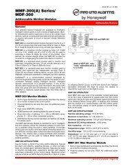
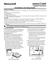
MODEL 5204 - Silent Knight
MODEL 5204 - Silent Knight
MODEL 5204 - Silent Knight

You also want an ePaper? Increase the reach of your titles
YUMPU automatically turns print PDFs into web optimized ePapers that Google loves.
Model <strong>5204</strong> Fire Control/Communicator Installation Manual6.2 Connections to Compatible <strong>Silent</strong> <strong>Knight</strong>ProductsThis section describes the connections of the following <strong>Silent</strong> <strong>Knight</strong> products:·• Model 4180 Status Display Module (see Section 6.2.1)• Model 5220 Direct Connect Module (see Section 6.2.2)• Model 5230 Remote Annunciator (see Section 6.2.3)• Model 5395 Distributed Power Module (see Section 6.2.4)• Model 5205 Dialer Module (see Section 5.7)• Model 7181 Zone Converter (see Section 6.2.5)Note: Once you have installed the <strong>5204</strong> and, if applicable, the 5230 and the 4180, test the basic system. Applypower, test the touchpad, then remove the power. Wire each auxiliary device with the power off. After youinstall each device, test it by re-applying the power. When you power up the <strong>5204</strong>, the two dots on the builtintouchpad display will alternately flash on and off.Note also that there is a 2-second power-up delay on the 5230.6.2.1 Model 4180 Status Display ModuleThe Model 4180 Status Display module provides remote annunciation of alarm and troublestatus information for each zone.The 4180 has 2 connectors, each of which has 8 outputs available for annunciation. Theseoutputs are active high at +12 VDC. Each output can provide up to 100 mA of current, with atotal limitation of 175 mA (when used with the <strong>5204</strong>). The module has 4 normally openrelays that are nondedicated, and therefore can be wired to be active with any of the outputs.The 4180 is not supervised. Table 6-4 shows the system status indicated by each LED.Do not use the 4180 relays in a 12 V <strong>5204</strong> installation.Table 6-4: Model 4180 ConnectionConnector P2 System Status Connector P3 System Status1 Alarm 1 1 Line #1 Trouble2 Alarm 2 2 Line #2 Trouble3 Alarm 3 3 Bell #1 Trouble4 Alarm 4 4 Bell #1 Trouble5 Trouble 1 5 Battery Trouble6 Trouble 2 6 AC Trouble7 Trouble 3 7 Silence Trouble8 Trouble 4 8 Dialer TroubleThe 4180 can be used to interface to long-range RF systems.6-6 150644