MODEL 5204 - Silent Knight
MODEL 5204 - Silent Knight
MODEL 5204 - Silent Knight

You also want an ePaper? Increase the reach of your titles
YUMPU automatically turns print PDFs into web optimized ePapers that Google loves.
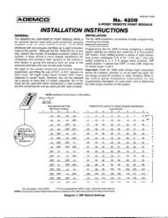
Model <strong>5204</strong> Fire Control/Communicator Installation Manual6.2.2.1 InstallationLocate the knockout on the right side of the <strong>5204</strong> cabinet to connect the 5220 using a shortpiece of conduit (must not exceed 20 feet in length).A four-wire pigtail is provided to wire the 5220 to the <strong>5204</strong>. Figure 6-5 shows how to wirethe Model 5220 Direct Connect module. The wiring chart uses bell #2 as the initiating loop.Program bell #2 to be active for the events to be reported.Figure 6-5 Model 5220 Wiring Diagram6.2.2.2 City Box Connect (24 VDC Systems Only)(For NFPA 72 Auxiliary Protected Fire Alarm systems for fire alarm service.)With the 5220, you can connect the <strong>5204</strong> directly to a municipal fire alarm box or "city box."The city (master) box is an enclosure that contains a manually operated transmitter used tosend an alarm to the municipal communication center, which houses the central operating partof the fire alarm system. To ensure communication of an active alarm status, use the 5220only with <strong>5204</strong> 24 V systems when connected to a series type DC master box.Wire the 5220 to the <strong>5204</strong> as shown in Figure 6-5. Wire the city box coil to terminals 3 and 4in the 5220. Maximum coil and wire resistance (combined) is 30 ohms.It is not possible to reset the remote indication until you clear the condition and reset the <strong>5204</strong>panel.Select relay 2 for 5220 city box. When you select 5220 operation, bell 2 and relay 2 cannot beused for any other purpose.Any zone programmed to activate bell 2 will cause an alarm to be sent.6-8 150644