Internet Communications Module 7845i - Patriot Alarm Systems, Inc.
Internet Communications Module 7845i - Patriot Alarm Systems, Inc.
Internet Communications Module 7845i - Patriot Alarm Systems, Inc.

Create successful ePaper yourself
Turn your PDF publications into a flip-book with our unique Google optimized e-Paper software.
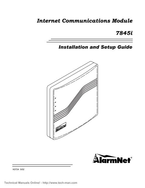
<strong>Internet</strong> <strong>Communications</strong> <strong>Module</strong><br />
<strong>7845i</strong><br />
Installation and Setup Guide<br />
K0724 5/02<br />
Technical Manuals Online! - http://www.tech-man.com
Technical Manuals Online! - http://www.tech-man.com
Table of Contents<br />
• • • • • • • • • • • • • • • • • • • • • • • • • • • • • • • • • • • • • • • • • • • • • • • • •<br />
Section 1 General Information .............................................................................................................1-1<br />
About <strong>Alarm</strong>Net-I................................................................................................................................................................ 1-1<br />
About <strong>7845i</strong> ......................................................................................................................................................................... 1-1<br />
System Features................................................................................................................................................................... 1-1<br />
Section 2 Mounting and Wiring ...........................................................................................................2-1<br />
Mounting <strong>7845i</strong> ................................................................................................................................................................... 2-1<br />
Wiring <strong>7845i</strong>........................................................................................................................................................................ 2-2<br />
Section 3 <strong>Communications</strong> Setup .........................................................................................................3-1<br />
General Information............................................................................................................................................................. 3-1<br />
Network Architecture ...................................................................................................................................................... 3-1<br />
<strong>7845i</strong> Connectivity........................................................................................................................................................... 3-1<br />
Typical Residential Broadband Network Methods.............................................................................................................. 3-1<br />
Cable Modem Technology Primer................................................................................................................................... 3-1<br />
ADSL (Asynchronous Digital Subscriber Line) Primer .................................................................................................. 3-2<br />
Section 4 Programming <strong>Alarm</strong>Net-i Using 7720P ..............................................................................4-1<br />
General Information............................................................................................................................................................. 4-1<br />
Default Parameters............................................................................................................................................................... 4-1<br />
Using a 7720P Programming Tool ...................................................................................................................................... 4-3<br />
Programming the <strong>7845i</strong> ....................................................................................................................................................... 4-4<br />
<strong>Alarm</strong>Net-i Menu............................................................................................................................................................. 4-5<br />
General Account Information (Questions 1-2) ................................................................................................................ 4-5<br />
Primary Account Information (Questions 3-5) ................................................................................................................ 4-5<br />
Secondary Account Information (Questions 6-9) ............................................................................................................ 4-5<br />
System Options (Questions 10-12) .................................................................................................................................. 4-5<br />
Reviewing <strong>Alarm</strong>Net-i Programming Entries.................................................................................................................. 4-7<br />
Getting to the Remote Access Menu from the <strong>Alarm</strong>Net-i Menu ................................................................................... 4-8<br />
Remote Access Menu ...................................................................................................................................................... 4-8<br />
General AUI Information (Questions 1-2)....................................................................................................................... 4-8<br />
Master Account Information (Questions 3-5).................................................................................................................. 4-8<br />
IP Address Information (Questions 6-10)........................................................................................................................ 4-8<br />
General Options (Questions 11-12) ................................................................................................................................. 4-9<br />
Reviewing Remote Access Programming Entries ........................................................................................................... 4-9<br />
Getting to the <strong>Alarm</strong>Net-i Menu from the Remote Access Menu ................................................................................... 4-9<br />
Setting Factory Defaults .................................................................................................................................................. 4-9<br />
Exiting Programming Mode ............................................................................................................................................ 4-9<br />
ECP Status Codes .......................................................................................................................................................... 4-10<br />
Section 5 Registration............................................................................................................................5-1<br />
Registering the <strong>7845i</strong>........................................................................................................................................................... 5-1<br />
Interactive Registration........................................................................................................................................................ 5-2<br />
Section 6 Summary of <strong>7845i</strong> LED Operation......................................................................................6-1<br />
<strong>7845i</strong> Status Display Operation ........................................................................................................................................... 6-1<br />
Status Display During Initial Power-up Sequence........................................................................................................... 6-2<br />
Message Status During Normal (Idle) State .................................................................................................................... 6-3<br />
Message Status During Software Downloading .............................................................................................................. 6-4<br />
Status Display Operation When Software Download Fails ............................................................................................. 6-4<br />
Network Connectivity Display ............................................................................................................................................ 6-5<br />
Section 7 Programmer Keyboard Commands ....................................................................................7-1<br />
Section 8 Getting Code Updates ...........................................................................................................8-1<br />
Updating the Code in the <strong>7845i</strong> ........................................................................................................................................... 8-1<br />
Section 9 Specifications .........................................................................................................................9-1<br />
Specifications....................................................................................................................................................................... 9-1<br />
Section 10 Glossary..............................................................................................................................10-1<br />
Glossary............................................................................................................................................................................. 10-1<br />
Technical Manuals Online! - http://www.tech-man.com<br />
i
<strong>Internet</strong> <strong>Communications</strong> <strong>Module</strong> <strong>7845i</strong> Installation and Setup Guide<br />
ii<br />
Technical Manuals Online! - http://www.tech-man.com
S E C T I O N 1<br />
General Information<br />
• • • • • • • • • • • • • • • • • • • • • • • • • • • • • • • • • • • • • • • • • • • • • • • • •<br />
In This Section<br />
♦ About <strong>Alarm</strong>Net-i<br />
♦ About <strong>7845i</strong><br />
♦ System Features<br />
• • • • • • • • • • • • • • • • • • • • • • • • • • • • • • • • • • • • • • • • • • • • • • • • •<br />
About <strong>Alarm</strong>Net-I<br />
About <strong>7845i</strong><br />
System Features<br />
<strong>Alarm</strong>Net-i is a fully encrypted; secure method of delivering alarm messages from a<br />
protected premise to an <strong>Alarm</strong>Net-i equipped central station. In a typical system, a <strong>7845i</strong><br />
<strong>Internet</strong> Communication <strong>Module</strong> or 8132 Advanced User Interface, routes status,<br />
supervisory, and alarm messages to the <strong>Alarm</strong>Net Control Center using a broadband<br />
<strong>Internet</strong> connection. <strong>Alarm</strong>Net Control identifies, validates and forwards the messages to<br />
the appropriate 7810iR Central Station Receiver. <strong>Alarm</strong>Net-i is implemented using TCP<br />
<strong>Internet</strong> protocol and 1024-bit encryption.<br />
<strong>7845i</strong> is the subscriber end of the <strong>Alarm</strong>Net-i reporting system. It is comparable to a digital<br />
communicator or long-range radio, but instead of transmitting signals over telephone lines or<br />
radio waves, it transmits alarm and status messages to the central monitoring station using<br />
a secure broadband <strong>Internet</strong> connection.<br />
Using the ECP keypad bus, the <strong>7845i</strong> sends status messages such as tamper and network<br />
communication failures to the control panel. ECP also provides Contact ID for messages<br />
being sent to the central station.<br />
• Report fire, burg, and status messages<br />
• Security system operation via Symphony remote access<br />
1. Arm System<br />
o Away<br />
o Stay<br />
o Night<br />
2. Disarm System<br />
3. User Codes - Allows authorized user to add or delete codes<br />
Technical Manuals Online! - http://www.tech-man.com<br />
1-1
<strong>Internet</strong> <strong>Communications</strong> <strong>Module</strong> <strong>7845i</strong> Installation and Setup Guide<br />
4. Bypass Zones - When system is not ready to arm, displays any open zones with:<br />
o<br />
o<br />
o<br />
o<br />
Zone number<br />
Zone description<br />
Status<br />
Bypass option<br />
5. Diagnostics<br />
6. Keypad Emulation<br />
• Control of the home environment, including the heating and air-conditioning system,<br />
lights, garage door, etc. via Symphony remote interface.<br />
• Programmable using 7720P Programming tool.<br />
1-2<br />
Technical Manuals Online! - http://www.tech-man.com
+<br />
+<br />
+<br />
S E C T I O N 2<br />
Mounting and Wiring<br />
• • • • • • • • • • • • • • • • • • • • • • • • • • • • • • • • • • • • • • • • • • • • • • • • •<br />
In This Section<br />
♦ Mounting <strong>7845i</strong><br />
♦ Wiring <strong>7845i</strong><br />
• • • • • • • • • • • • • • • • • • • • • • • • • • • • • • • • • • • • • • • • • • • • • • • • •<br />
Mounting <strong>7845i</strong><br />
<strong>7845i</strong> must be mounted indoors. To mount <strong>7845i</strong>, see Figure 1 and complete the following<br />
steps:<br />
1. Detach the case back by pushing up into the two tabs located at the bottom of <strong>7845i</strong> with<br />
the blade of a screwdriver while pulling the case back and case front apart.<br />
2. Locate the case back over the mounting surface such that the opening in the case back is<br />
aligned with the wire/cable access opening (in the mounting surface) while passing the<br />
wires/cable through the opening in the case back.<br />
3. Secure the case back to the mounting surface using four screws (supplied).<br />
Prior to attaching the case front to the case back, be sure to wire the <strong>7845i</strong> as described in the<br />
"Wiring <strong>7845i</strong>" paragraph in this section.<br />
MOUNTING<br />
SCREW<br />
(TYP)<br />
(4)<br />
+<br />
+<br />
+<br />
WALL OR<br />
MOUNTING<br />
SURFACE<br />
REAR<br />
COVER<br />
PANEL<br />
FRONT<br />
COVER<br />
PANEL<br />
Figure 1. Mounting <strong>7845i</strong><br />
7845I-003-V0<br />
2-1<br />
Technical Manuals Online! - http://www.tech-man.com
<strong>Internet</strong> <strong>Communications</strong> <strong>Module</strong> <strong>7845i</strong> Installation and Setup Guide<br />
Wiring <strong>7845i</strong><br />
Connect <strong>7845i</strong> in parallel with Keypads and other peripheral devices using the Keypad data<br />
(ECP) bus. To wire, see the Summary of Connections diagram at the rear of this guide and do<br />
the following.<br />
Unshielded, 22 AWG cable is recommended for <strong>7845i</strong> power/data wires.<br />
Connect the wires to the header as follows:<br />
1. Connect the Data Out terminal (pin 9) of the control panel to the Data In terminal of<br />
<strong>7845i</strong> (yellow wire).<br />
2. Connect the Data In terminal (pin 8) of the control panel to the Data Out terminal of<br />
<strong>7845i</strong> (green wire).<br />
3. Connect the AUX + terminal (pin 6) of the control panel to the +12VDC terminal of <strong>7845i</strong><br />
(red wire).<br />
4. Connect the AUX – terminal (pin 7) to the GND terminal of <strong>7845i</strong> (black wire).<br />
5. Connect one end of the Ethernet cable (Category 5) to <strong>7845i</strong>’s RJ45 Ethernet connector<br />
and the other end to cable/DSL router.<br />
UL<br />
Use a Listed cable/DSL router suited for the application.<br />
6. Attach the case front of <strong>7845i</strong> to the case back. Attach the top of <strong>7845i</strong> first, then press<br />
the bottom section inward until it snaps into place securely.<br />
2-2<br />
Technical Manuals Online! - http://www.tech-man.com
S E C T I O N 3<br />
<strong>Communications</strong> Setup<br />
• • • • • • • • • • • • • • • • • • • • • • • • • • • • • • • • • • • • • • • • • • • • • • • • •<br />
In This Section<br />
♦ General Information<br />
♦ Network Architecture<br />
♦ <strong>7845i</strong> Connectivity<br />
♦ Typical Residential Broadband Network Methods<br />
♦ Cable Modem Technology Primer<br />
♦ ADSL (Asynchronous Digital Subscriber Line) Primer<br />
• • • • • • • • • • • • • • • • • • • • • • • • • • • • • • • • • • • • • • • • • • • • • • • • •<br />
General Information<br />
This section provides an overview of networking techniques and methods commonly used in<br />
home and commercial Local Area Networks (LANs). While no single method described here<br />
may apply to your specific <strong>7845i</strong> installation, the information should serve as a framework<br />
for increasing your general understanding of data network applications.<br />
Network Architecture<br />
This overview describes several typical LAN configurations:<br />
• Cable Modem (DOCSIS)<br />
• ADSL (Advanced Digital Subscriber Line)<br />
• Dial on Demand Router<br />
<strong>7845i</strong> Connectivity<br />
The <strong>7845i</strong> connects to any of these network variants in the same manner; via an Ethernet<br />
cable (10BaseT), terminating in an RJ45 connector. Although <strong>7845i</strong> provides its own<br />
security and does not require a firewall, it is recommended that in most installations, <strong>7845i</strong><br />
be connected through a Firewall/Router device, which will enable the device to be connected<br />
to the home network without altering the connections of any other device on the network.<br />
Typical Residential Broadband Network Methods<br />
There are two typical “broadband” (high data rate) networking solutions available to the U.S.<br />
residential market: Cable Modem and ADSL. Currently, Cable Modem technology has the<br />
largest number of residential subscribers, since ADSL has certain range limitations that do<br />
not affect fiberoptic/coaxial cable networks. This section provides some background<br />
information on the technologies themselves.<br />
Cable Modem Technology Primer<br />
Cable systems were originally designed to deliver broadcast television signals efficiently to<br />
subscribers' homes. To ensure that consumers could obtain cable service with the same TV<br />
sets they use to receive over-the-air broadcast TV signals, cable operators recreate a portion<br />
of the over-the-air radio frequency (RF) spectrum within a sealed coaxial cable line.<br />
Traditional coaxial cable systems typically operate with 330 MHz or 450 MHz of capacity,<br />
whereas modern hybrid fiber/coax (HFC) systems are expanded to 750 MHz or more.<br />
Technical Manuals Online! - http://www.tech-man.com<br />
3-1
<strong>Internet</strong> <strong>Communications</strong> <strong>Module</strong> <strong>7845i</strong> Installation and Setup Guide<br />
3-2<br />
Logically, downstream video programming signals begin around 50 MHz, the equivalent of<br />
channel 2 for over-the-air television signals. The 5 MHz - 42 MHz portion of the spectrum is<br />
usually reserved for upstream communications from subscribers' homes.<br />
Each standard television channel occupies 6 MHz of RF spectrum. Thus a traditional cable<br />
system with 400 MHz of downstream bandwidth can carry the equivalent of 60 analog TV<br />
channels and a modern HFC system with 700 MHz of downstream bandwidth has the<br />
capacity for some 110 channels.<br />
To deliver data services over a cable network, one television channel (in the 50 - 750 MHz<br />
range) is typically allocated for downstream traffic to homes and another channel (in the 5 -<br />
42 MHz band) is used to carry upstream signals.<br />
A headend cable modem termination system (CMTS) communicates through these channels<br />
with cable modems located in subscriber homes to create a virtual local area network (LAN)<br />
connection. Most cable modems are external devices that connect to a personal computer<br />
(PC) through a standard 10Base-T Ethernet card or Universal Serial Bus (USB) connection,<br />
although internal PCI modem cards are also available.<br />
The cable modem access network operates at Layer 1 (physical) and Layer 2 (media access<br />
control/logical link control) of the Open System Interconnect (OSI) Reference Model. Thus,<br />
Layer 3 (network) protocols, such as IP traffic, can be seamlessly delivered over the cable<br />
modem platform to end users.<br />
A single downstream 6 MHz television channel may support up to 27 Mbps of downstream<br />
data throughput from the cable headend using 64 QAM (quadrature amplitude modulation)<br />
transmission technology. Speeds can be boosted to 36 Mbps using 256 QAM. Upstream<br />
channels may deliver 500 kbps to 10 Mbps from homes using 16QAM or QPSK (quadrature<br />
phase shift key) modulation techniques, depending on the amount of spectrum allocated for<br />
service. This upstream and downstream bandwidth is shared by the active data subscribers<br />
connected to a given cable network segment, typically 500 to 2,000 homes on a modern HFC<br />
network.<br />
An individual cable modem subscriber may experience access speeds from 500 kbps to 1.5<br />
Mbps or more (depending on the network architecture and traffic load); blazing performance<br />
compared to dial-up alternatives. However, when surfing the Web, performance can be<br />
affected by <strong>Internet</strong> backbone congestion.<br />
In addition to speed, cable modems offer another key benefit: constant connectivity. Because<br />
cable modems use connectionless technology, much like in an office LAN, a subscriber's PC is<br />
always online with the network. That means there's no need to dial-in to begin a session, so<br />
users do not have to worry about receiving busy signals. Additionally, going online does not<br />
tie up their telephone line, which is very important in an emergency reporting situation.<br />
ADSL (Asynchronous Digital Subscriber Line) Primer<br />
Asymmetric Digital Subscriber Line (ADSL) is a competing modem technology that converts<br />
existing twisted-pair telephone lines into access paths for multimedia and high-speed data<br />
communications. ADSL can transmit up to 6 Mbps to a subscriber, and as much as 832 kbps<br />
or more in both directions.<br />
An ADSL circuit connects an ADSL modem on each end of a twisted-pair telephone line,<br />
creating three information channels -- a high-speed downstream channel, a medium speed<br />
duplex channel, depending on the implementation of the ADSL architecture, and a POTS<br />
(Plain Old Telephone Service) or an ISDN channel. The POTS/ISDN channel is split off from<br />
the digital modem by filters, thus guaranteeing uninterrupted POTS/ISDN, even if ADSL<br />
fails. The high-speed channel ranges from 1.5 to 6.1 Mbps, while duplex rates range from 16<br />
Technical Manuals Online! - http://www.tech-man.com
Section 3: <strong>Communications</strong> Setup<br />
to 832 kbps. Each channel can be sub-multiplexed to form multiple, lower rate channels,<br />
depending on the system.<br />
ADSL modems provide data rates consistent with North American and European digital<br />
hierarchies and can be purchased with various speed ranges and capabilities. The minimum<br />
configuration provides 1.5 or 2.0 Mbps downstream and a 16-kbps duplex channel; others<br />
provide rates of 6.1 Mbps and 64 kbps duplex. Products with downstream rates up to 8 Mbps<br />
and duplex rates up to 640 kbps are available today. ADSL modems will accommodate ATM<br />
transport with variable rates and compensation for ATM overhead, as well as IP protocols.<br />
Downstream data rates depend on a number of factors, including the length of the copper<br />
line, its wire gauge, presence of bridged taps, and cross-coupled interference. Line<br />
attenuation increases with line length and frequency, and decreases as wire diameter<br />
increases.<br />
Technical Manuals Online! - http://www.tech-man.com<br />
3-3
<strong>Internet</strong> <strong>Communications</strong> <strong>Module</strong> <strong>7845i</strong> Installation and Setup Guide<br />
3-4<br />
Technical Manuals Online! - http://www.tech-man.com
S E C T I O N 4<br />
Programming <strong>Alarm</strong>Net-i Using 7720P<br />
• • • • • • • • • • • • • • • • • • • • • • • • • • • • • • • • • • • • • • • • • • • • • • • • •<br />
In This Section<br />
♦ General Information<br />
♦ Default Parameters<br />
♦ Using a7720P Programming Tool<br />
♦ 7720P Keyboard Commands<br />
♦ Programming the <strong>7845i</strong><br />
♦ Reviewing <strong>Alarm</strong>Net-i Programming Entries<br />
♦ Getting to the Remote Access Menu from the<br />
<strong>Alarm</strong>Net-i Menu<br />
♦ Reviewing Remote Access Programming Entries<br />
♦ Getting to the <strong>Alarm</strong>Net-i Menu from the Remote<br />
Access Menu<br />
♦ Setting Factory Defaults<br />
♦ Exiting Programming Mode<br />
♦ ECP Status Codes<br />
• • • • • • • • • • • • • • • • • • • • • • • • • • • • • • • • • • • • • • • • • • • • • • • • •<br />
General Information<br />
Default Parameters<br />
There are two <strong>7845i</strong> programming sections accessible from the 7720P Programming Tool:<br />
<strong>Alarm</strong>Net-i and Remote Access.<br />
At a minimum, the <strong>7845i</strong> must be programmed for <strong>Alarm</strong>Net-i to enable 1024 bit, encrypted<br />
alarm reporting to the central station via the <strong>Internet</strong>. Information such as <strong>Alarm</strong>Net<br />
account number (ID, City and CS) as well reporting options like Old <strong>Alarm</strong> Time and<br />
Supervision Time are entered. An <strong>Alarm</strong>Net account number is required to complete this.<br />
Remote Access programming is used to activate Symphony home control features such as<br />
security system control, heating and cooling control and lighting control. Once enabled with<br />
the 7720P, Symphony home control features on the <strong>7845i</strong> are accessed via the <strong>Internet</strong> using<br />
the same 1024 bit encryption to insure security. Remote Access must be programmed using<br />
a 7720P with a Symphony Master Account number prior to accessing a <strong>7845i</strong> from a remote<br />
computer.<br />
A <strong>7845i</strong> fresh out of the box has many parameters set to default values. These values for the<br />
<strong>Alarm</strong>Net-i features are listed in Table 1.<br />
The default values for Remote Access Programming Features are listed below in Table 2.<br />
4-1<br />
Technical Manuals Online! - http://www.tech-man.com
<strong>Internet</strong> <strong>Communications</strong> <strong>Module</strong> <strong>7845i</strong> Installation and Setup Guide<br />
Table 1. <strong>7845i</strong> Programming Defaults Summary for <strong>Alarm</strong>Net-i Programming Features<br />
PROGRAMMING OPTION<br />
1 En.<strong>Alarm</strong>NetI Y<br />
2 Use Mstr Act N<br />
3 Primary City ID xx<br />
4 Primary CS ID xx<br />
5 Primary Sub ID xxxx<br />
6 En. 2nd CS Y/N N<br />
7 ANI ECP Address 3<br />
8 Report Priority Stand Alone<br />
9 Supervision 24 hours<br />
10 Old <strong>Alarm</strong> Time 10 minutes<br />
11 Flt Time (min) 5<br />
STANDARD DEFAULT<br />
VALUE<br />
ACTUAL ENTRY<br />
Table 2. <strong>7845i</strong> Programming Defaults Summary for Remote Access Programming Features<br />
PROGRAMMING OPTION<br />
1 En.Rem AccessY/N N<br />
2 AUI ECP Address 1<br />
3 Master CS ID xxxx<br />
4 Secondary CS ID xxxx<br />
5 Subscriber ID xxxx<br />
6 Use DHCP Y/N Y<br />
7 RCPP Serv Y/N Y<br />
8 Lighting Y/N N<br />
STANDARD DEFAULT<br />
VALUE<br />
ACTUAL ENTRY<br />
4-2<br />
Technical Manuals Online! - http://www.tech-man.com
Using a 7720P Programming Tool<br />
Section 4: Programming <strong>Alarm</strong>Net-i and Remote Access using 7720P<br />
The <strong>7845i</strong> powers the 7720P Programming Tool via the programming jack.<br />
Each key of the 7720P has two possible functions: a normal function and a Shift function. To<br />
perform a normal key function, simply press the desired key. To perform a Shift function,<br />
press the [shift] key, and then press the appropriate key. For a description of each normal<br />
and shift key function, refer to Table 3.<br />
Table 3. 7720P Normal and Shift Key (shift LED lit) Functions<br />
KEY NORMAL KEY FUNCTION SHIFT KEY FUNCTION<br />
BS/ESC [BS]: Press to delete entry [ESC]: Press to quit program mode; also can<br />
reset EEPROM defaults*<br />
↓/↑ [↓]: Scroll down programming [↑]: Scroll up programming<br />
N/Y [N]: Press for "NO" answer [Y]: Press SHIFT-Y for "YES" answer<br />
SHIFT<br />
Press before pressing a SHIFT key function. Will light SHIFT LED. LED goes out<br />
once a key is pressed. Press again for each SHIFT function desired.<br />
1/A [1]: For entering the number 1 [A]: For entering letter A<br />
2/B [2]: For entering the number 2 [B]: For entering letter B<br />
3/C [3]: For entering the number 3 [C]: For entering letter C<br />
4/D [4]: For entering the number 4 [D]: For entering letter D<br />
5/E [5]: For entering the number 5 [E]: For entering letter E<br />
6/F [6]: For entering the number 6 [F]: For entering letter F<br />
7/S [7]: For entering the number 7 [S]: For entering letter S<br />
8/T [8]: For entering the number 8 [T]: For entering letter T<br />
9/X [9]: For entering the number 9 [X]: For entering letter X<br />
SPACE [SPACE]: For scrolling option list No SHIFT function<br />
0 [0]: For entering the number 0 No SHIFT function<br />
#/ENTER [#/ENTER]: Press to accept entries No SHIFT function<br />
* Active only when the "REVIEW?" prompt is displayed.<br />
Technical Manuals Online! - http://www.tech-man.com<br />
4-3
<strong>Internet</strong> <strong>Communications</strong> <strong>Module</strong> <strong>7845i</strong> Installation and Setup Guide<br />
Programming the <strong>7845i</strong><br />
Provided that the initial power up sequence has completed and the 7720P cable is connected<br />
to the already powered the <strong>7845i</strong>, you may proceed with programming the <strong>7845i</strong>.<br />
Programming is accomplished by answering displayed questions. Most questions require<br />
only a [Y]es or [N]o response, while others require a numerical response (ID numbers, etc.).<br />
Press [ENTER] key to accept each response and proceed to the next question. The current<br />
value is displayed on the second line in parentheses ( ). A "?" indicates an invalid entry. To<br />
accept the current entry, press the [ENTER] key. If the current value is an invalid entry,<br />
pressing the [ENTER] key causes the display to repeat the unanswered question; the next<br />
question is not displayed until a valid answer is entered. Use the up/down arrow keys to<br />
scroll through the programming questions without changing any values. Press the [ESC]<br />
key to go to the end of the list of questions.<br />
Enter programming mode by pressing [ENTER] AFTER the initial power-up sequence<br />
(refer to Section 6: Summary of <strong>7845i</strong> LED Operation). To make sure that the user really<br />
meant to enter program mode, the following prompt appears:<br />
Strt Prog Mode?<br />
Y/N _<br />
Press [Y] if programming is desired, otherwise, press [N].<br />
The user has the choice of two programming menus:<br />
<strong>Alarm</strong>Net-i Programming OR<br />
Remote Access Programming<br />
These choices will be presented via the following prompts:<br />
Program AlmNetI?<br />
Y/N _<br />
Program Remote<br />
Access? Y/N _<br />
If neither is chosen, the following prompt is displayed:<br />
Exit Prog Mode?<br />
Y/N _<br />
If [N] is pressed, the display will loop back up to the “Program AlmNetI?” choice and the cycle is repeated<br />
until one of the prompts is answered with [Y].<br />
Note that both menus can be accessed in one programming session.<br />
4-4<br />
Technical Manuals Online! - http://www.tech-man.com
Section 4: Programming <strong>Alarm</strong>Net-i and Remote Access using 7720P<br />
<strong>Alarm</strong>Net-i Menu<br />
General Account Information (Questions 1-2)<br />
Question 1. En.<strong>Alarm</strong>NetI Y/N Press [Y] to enable <strong>Alarm</strong>Net-i functionality.<br />
Press [N] to disable <strong>Alarm</strong>Net-i functionality.<br />
Question 2. Use Mstr Act Y/N Press [Y] to use the account information assigned to<br />
Remote Access (skip to question 6).<br />
Press [N] to use <strong>Alarm</strong>Net-i specific account information<br />
Primary Account Information (Questions 3-5)<br />
Question 3. Primary City ID Enter the 2-digit primary city code, 01-99 (decimal).<br />
Question 4. Primary CS ID Enter the primary central station's system ID number, 01-<br />
FE.<br />
Question 5. Primary Sub ID Enter the 4-digit customer account number, 0001-9999.<br />
Secondary Account Information (Questions 6-9)<br />
Question 6. En. 2nd CS Y/N Press [Y] if redundant reporting to a second central station<br />
is desired.<br />
Press [N] if not desired (skip to question 10).<br />
Question 7. 2nd City ID Enter the 2-digit secondary city code, 01-99 (decimal).<br />
Question 8. 2nd CS ID Enter the secondary central station's system ID number,<br />
01-FE.<br />
Question 9. 2nd Sub ID Enter the secondary 4-digit customer account number,<br />
0001-9999.<br />
System Options (Questions 10-12)<br />
Question 10. ANI ECP Addr Enter the ECP device address on which the <strong>7845i</strong><br />
communicates with the panel as an <strong>Alarm</strong>Net-i (LRR)<br />
product. For VIA 30+, VISTA-10SE, and VISTA-20SE this<br />
must be address 3. For other control panels, see the<br />
control panel’s Installation and Setup Guide.<br />
UL<br />
Dual reporting is required for UL installations. For<br />
example <strong>Internet</strong> with dialer backup.<br />
Technical Manuals Online! - http://www.tech-man.com<br />
4-5
<strong>Internet</strong> <strong>Communications</strong> <strong>Module</strong> <strong>7845i</strong> Installation and Setup Guide<br />
UL<br />
UL<br />
Question 11.<br />
Question 12<br />
Report Priority<br />
(Stand Alone)<br />
Supervision<br />
(24 Hours)<br />
Must be set to 5 minutes for UL installations.<br />
Question 13.<br />
Old <strong>Alarm</strong> Time<br />
(10 Minutes)<br />
Old alarm time must be set to 10 minutes for UL installations.<br />
This selection sets the device priority for systems with<br />
multiple communication devices. If the system has no<br />
other communication device, then this option should be set<br />
to “Stand Alone” which is the default priority. For<br />
duplicate reporting, the priority should be set to<br />
“Secondary”. The secondary device is NOT responsible for<br />
the ECP communication (handshake) with the panel; it<br />
just reports the alarms that are sent to the primary device.<br />
If the primary device loses communication with the panel,<br />
then no alarms are sent by either device.<br />
To toggle between the two choices, use the [space] and<br />
[backspace] keys<br />
Press the [Enter] key to select the priority displayed.<br />
This selection sets the supervision timing for 24 hour, 1<br />
hour or 5 minutes. The default supervision timing is 24<br />
hours. The <strong>7845i</strong> sends a supervision message once during<br />
the supervision period. <strong>Alarm</strong>Net transmits a<br />
communications failure alarm to the central station if the<br />
supervision message is not received within the period.<br />
To scroll through the available choices:<br />
• Press the [space] key to scroll forward through the list<br />
of choices.<br />
• Press the [backspace] key to scroll back through the<br />
list if the desired entry has scrolled past.<br />
Press the [Enter] key to select the time displayed.<br />
The old alarm time sets how long an undeliverable alarm<br />
is retried for delivery to <strong>Alarm</strong>Net. If the message is not<br />
validated, it is retried until the old alarm time is reached<br />
or the message is validated. The choices available are: 10<br />
Min., 15 Min., 30 Min., 1 Hr, 2Hr, 4Hr, 8Hr., 12Hr and<br />
24Hr.<br />
To scroll through the available choices:<br />
• Press the [space] key to scroll forward through the list<br />
of choices.<br />
• Press the [backspace] key to scroll back through the<br />
list if the desired entry has scrolled past.<br />
Press the [Enter] key to select the time displayed.<br />
Question 14. Flt Time (min) Enter in minutes 1 - 99 the time delay before the <strong>7845i</strong><br />
notifies the control panel that there is loss of contact with<br />
the network. The <strong>7845i</strong> will alert the control panel of the<br />
loss of contact with the network via the status message.<br />
Refer to Table 4 in this Section for more information<br />
regarding the ECP Status Codes.<br />
UL<br />
The time for <strong>7845i</strong> to report lost communications to the Control Panel must be 1 minute for UL<br />
installations.<br />
4-6<br />
Technical Manuals Online! - http://www.tech-man.com
Section 4: Programming <strong>Alarm</strong>Net-i and Remote Access using 7720P<br />
Reviewing <strong>Alarm</strong>Net-i Programming Entries<br />
When the last question is answered the following is displayed:<br />
Review <strong>Alarm</strong>NetI?<br />
To review the <strong>Alarm</strong>Net-i programming options (to ensure that the correct responses have<br />
been made), press [Y]. The programming questions are displayed again, starting with<br />
Question 1 of this menu. Use the up/down arrow keys to scroll through the program fields<br />
without changing any of the values. If a value requires change, simply type in the correct<br />
value. When the last field is displayed, the “Review <strong>Alarm</strong>NetI?” question again appears.<br />
Technical Manuals Online! - http://www.tech-man.com<br />
4-7
<strong>Internet</strong> <strong>Communications</strong> <strong>Module</strong> <strong>7845i</strong> Installation and Setup Guide<br />
Getting to the Remote Access Menu from the <strong>Alarm</strong>Net-i Menu<br />
Once the <strong>Alarm</strong>Net-i programming menu has been completed and the answer to “Review<br />
<strong>Alarm</strong>NetI?” is [N]o, the following is displayed:<br />
Remote Acc Prog?<br />
The Remote Access Menu can now be viewed by pressing [Y]. If this is not desired, press [N]<br />
and the following is displayed:<br />
Exit Prog Mode?<br />
Y/N<br />
As is the case at the entry of program mode, the menu choices and the option to exit program<br />
mode are repeated until one of the prompts is answered with [Y].<br />
Remote Access Menu<br />
UL<br />
Remote access and lighting control have not been evaluated by UL.<br />
General AUI Information (Questions 1-2)<br />
Question 1. En.Rem AccessY/N Press [Y] to enable remote access through Symphony<br />
services.<br />
Press [N] to disable remote access through Symphony<br />
services.<br />
Question 2. AUI ECP Address Enter the ECP device address on which the <strong>7845i</strong> will<br />
communicate with the control panel as an AUI.<br />
Master Account Information (Questions 3-5)<br />
Question 3. Master CS ID Enter the 4-digit Master Central Station ID.<br />
Question 4. Secondary CS ID Enter the 4-digit Secondary Central Station ID.<br />
Question 5. Subscriber ID Enter the 4-digit customer account number.<br />
IP Address Information (Questions 6-10)<br />
Question 6. Use DHCP? Y/N Press [Y] if it desired to have the IP addresses dynamically<br />
allocated (skip to question 11).<br />
Press [N] if fixed IP addresses are desired.<br />
Question 7. NIC IP Address Enter the 4-part IP address for this device. The 4 parts of<br />
the address must be separated by spaces.<br />
Question 8. Subnet Mask Enter the 32-bit address mask used to indicate the portion<br />
(bits) of the IP address that is being used for the subnet<br />
address. The 4 parts of the address must be separated by<br />
spaces.<br />
Question 9. Gateway IP Addr Enter the 4-part IP address assigned to the Gateway. The<br />
4 parts of the address must be separated by spaces.<br />
4-8<br />
Technical Manuals Online! - http://www.tech-man.com
Section 4: Programming <strong>Alarm</strong>Net-i and Remote Access using 7720P<br />
Question 10. DNS Serv IP Addr Enter the 4-part IP address assigned to the DNS (Domain<br />
Name System) server. The 4 parts of the address must be<br />
separated by spaces.<br />
General Options (Questions 11-12)<br />
Question 11. RCPP Serv Y/N Press [Y] to allow access to the Remote Control Proxy<br />
Protocol Service.<br />
Press [N] if access to the Remote Control Proxy Protocol<br />
Service is not desired.<br />
Question 12. Lighting Y/N Press [Y] to enable the Lighting Control buttons through<br />
remote access.<br />
Press [N] to disable the Lighting Control buttons through<br />
remote access.<br />
Reviewing Remote Access Programming Entries<br />
When the last question is answered the following is displayed:<br />
Review Rem Acc?<br />
To review the Remote Access programming options (to ensure that the correct responses<br />
have been made), press [Y]. The programming questions are displayed again, starting with<br />
Question 1 of this menu. Use the up/down arrow keys to scroll through the program fields<br />
without changing any of the values. If a value requires change, simply type in the correct<br />
value. When the last field is displayed, the “Review Rem Acc?” question again appears.<br />
Getting to the <strong>Alarm</strong>Net-i Menu from the Remote Access Menu<br />
Once the Remote Access programming menu has been completed and the answer to “Review<br />
Rem Acc?” is [N]o, following is displayed:<br />
<strong>Alarm</strong>NetI Prog?<br />
The <strong>Alarm</strong>Net-i Menu can now be viewed by pressing [Y]. If this is not desired, press [N]<br />
and the following will be displayed:<br />
Exit Prog Mode?<br />
Y/N<br />
As is the case at the entry of program mode, the menu choices and the option to exit program<br />
mode are repeated until one of the prompts is answered with [Y].<br />
Setting Factory Defaults<br />
Reset the programming options to factory-default values (as listed in Tables 1 and 2) by<br />
pressing [ESC] at the “Exit Prog Mode?” prompt. A confirmation prompt appears. Press [Y]<br />
to default the values, or press [N] to cancel this function. If you press [Y], all programmed<br />
values of both menus are reset to the original factory settings.<br />
Exiting Programming Mode<br />
To exit the programming mode, press [Y] in response to the “Exit Prog Mode?” question.<br />
Upon exiting, the root file is updated to log the changes made. A message is displayed telling<br />
the user that this step is being executed. When complete, the message “DONE” is displayed<br />
to indicate the programming session has ended. If critical configuration changes were made<br />
during programming, the <strong>7845i</strong> will reset to ensure that the programmed features are<br />
enabled.<br />
Technical Manuals Online! - http://www.tech-man.com<br />
4-9
<strong>Internet</strong> <strong>Communications</strong> <strong>Module</strong> <strong>7845i</strong> Installation and Setup Guide<br />
ECP Status Codes<br />
The <strong>7845i</strong> sends status messages to the control panel for tamper and network<br />
communication failures. When using ADEMCO’s low-end control panels (VISTA-10SE,<br />
VISTA-20SE, VIA-30P, the status is displayed on the control panel’s keypad as “Long Rnge<br />
Fail” followed by a 4-digit code). These codes are listed in Table 4, as well as Contact ID<br />
codes (listed in Table 5) that are sent to the central station.<br />
STATUS CODE<br />
Table 4. ECP Keypad Displays Status Codes<br />
DESCRIPTION<br />
0000 Control panel lost communication with <strong>7845i</strong><br />
0880 <strong>7845i</strong> tamper detected (cover removed)<br />
0005 <strong>7845i</strong> has lost contact with <strong>Alarm</strong>Net<br />
000F<br />
<strong>7845i</strong> is not registered; radio account not activated<br />
0400 <strong>7845i</strong> Power On Reset.<br />
0C80<br />
0C8F<br />
CODE*<br />
R330 C8xx**<br />
E339 C8xx**<br />
E341 C8xx**<br />
R341 C8xx**<br />
E355 C000<br />
R355 C000<br />
<strong>7845i</strong> Power On Reset & Tamper detected<br />
<strong>7845i</strong> Power On Reset & Tamper detected & Not Registered<br />
Table 5. ECP Contact ID (685 Displays) Codes<br />
DESCRIPTION<br />
Restore of RF faults (restore of peripheral trouble)<br />
ECP power-on reset<br />
ECP tamper<br />
ECP tamper restore<br />
* As displayed on 685 Digital Receiver.<br />
** xx = <strong>7845i</strong> device address.<br />
Radio lost communication with control panel<br />
Radio restore communication with control panel<br />
4-10<br />
Technical Manuals Online! - http://www.tech-man.com
Section 4: Programming <strong>Alarm</strong>Net-i and Remote Access using 7720P<br />
Technical Manuals Online! - http://www.tech-man.com<br />
4-11
Technical Manuals Online! - http://www.tech-man.com
S E C T I O N 5<br />
Registration<br />
• • • • • • • • • • • • • • • • • • • • • • • • • • • • • • • • • • • • • • • • • • • • • • • • •<br />
In This Section<br />
♦ Registering the <strong>7845i</strong><br />
♦ Interactive Registration<br />
• • • • • • • • • • • • • • • • • • • • • • • • • • • • • • • • • • • • • • • • • • • • • • • • •<br />
Registering the <strong>7845i</strong><br />
Once you have initialized and programmed the <strong>7845i</strong>, it must registered with <strong>Alarm</strong>Net<br />
Control. An unregistered <strong>7845i</strong> is indicated on the Status Display as: TX lit, Message Status<br />
blinking, and Fault not lit. The <strong>Internet</strong> Link may be lit or blinking. Refer to Section 6 for a<br />
detailed discussion of LED operation.<br />
TX, green<br />
Message Status, yellow<br />
Fault, red<br />
<strong>Internet</strong> Link, yellow<br />
Figure 2. Unregistered <strong>7845i</strong> Status Display In Normal Operation<br />
Throughout this document, the following key is used to describe LED state:<br />
ON OFF FAST BLINK SLOW BLINK<br />
Figure 3. LED Key<br />
To complete the registration process, a <strong>7845i</strong> transmits a registration message and receives a<br />
registration validation from <strong>Alarm</strong>Net Control.<br />
Initiate the registration sequence by either clicking the tamper switch three times or by<br />
pressing [shift] and the up arrow [↑] on the 7720P. If you are using a 7720P, skip to the<br />
"Interactive Registration" paragraph in this section.<br />
You can monitor the registration process by viewing the Status Display. The Message Status<br />
(yellow) LED will go on solid indicating that the registration message is pending. The TX<br />
(green) LED will blink rapidly when the registration is accepted.<br />
5-1<br />
Technical Manuals Online! - http://www.tech-man.com
<strong>Internet</strong> <strong>Communications</strong> <strong>Module</strong> <strong>7845i</strong> Installation and Setup Guide<br />
1 2 3 4 5<br />
6 7 8 9<br />
TX, green<br />
Message Status, yellow<br />
Fault, red<br />
<strong>Internet</strong> Link, yellow<br />
Interactive Registration<br />
1. Unregistered, normal operation<br />
2. Registration message pending<br />
3. Registration message transmitted<br />
4. Registration accepted by <strong>Alarm</strong>Net<br />
5. Registered, normal operation<br />
6. Power-on reset message pending<br />
7. Power-on reset message transmitted<br />
8. Power-on reset message acknowledged by <strong>Alarm</strong>Net<br />
9. Normal operation<br />
Once the registration has been completed successfully, the <strong>7845i</strong> enters normal operating<br />
mode; the TX (green) LED goes out and the Message Status (yellow) LED is lit to indicate<br />
that the power-on / reset message is waiting to be sent. If registration is not validated<br />
within 30 seconds, the <strong>7845i</strong> times out.<br />
If repeated registration attempts time out, check your <strong>Internet</strong> connection and verify that<br />
<strong>7845i</strong> account information has been entered correctly.<br />
The interactive registration feature allows the installer to register the <strong>7845i</strong> through a series<br />
of keyboard commands on the 7720P Programming Tool. This method of registration lets the<br />
installer monitor the registration process.<br />
Registering …<br />
Registration<br />
SUCCESS<br />
Once the installation is complete, press the [↑] key on<br />
the 7720P. The registration message is sent and the<br />
unit waits for the acknowledgment.<br />
If this is a new installation and the city, central station,<br />
and customer numbers have been correctly entered, the<br />
<strong>7845i</strong> is registered and this message is displayed. At this<br />
point, the <strong>7845i</strong> is in full service and available for alarm<br />
reporting to the central station.<br />
5-2<br />
Technical Manuals Online! - http://www.tech-man.com
Section 5: Registration<br />
Possible Errors<br />
Registration BAD<br />
Timed Out<br />
Registration BAD<br />
Pri Sub ID BAD<br />
Registration BAD<br />
2nd Sub ID BAD<br />
Registration BAD<br />
Pri&2nd IDs BAD<br />
Registration BAD<br />
Pri ID – Need PIN<br />
Registration BAD<br />
2nd ID – Need PIN<br />
Registration BAD<br />
Pri&2nd – Need PIN<br />
If no response to the registration request is received<br />
from <strong>Alarm</strong>Net, this message is displayed.<br />
The city, central station, or customer number for the<br />
Primary account is not accepted. The ID information<br />
was either entered in error, or the central station failed<br />
to pre-authorize programmed ID numbers with<br />
<strong>Alarm</strong>Net customer service.<br />
The city, central station, or customer number for the<br />
Secondary account is not accepted. The ID information<br />
was either entered in error, or the central station failed<br />
to pre-authorize programmed ID numbers with<br />
<strong>Alarm</strong>Net customer service.<br />
The city, central station, or customer number for BOTH<br />
the Primary and Secondary accounts are not accepted.<br />
The ID information was either entered in error, or the<br />
central station failed to pre-authorize programmed ID<br />
numbers with <strong>Alarm</strong>Net customer service.<br />
This prompt is displayed if this is a repair/replacement,<br />
or an error was made in programming the Primary<br />
account information of <strong>7845i</strong> for an existing account.<br />
This prompt appears for two seconds. See the <strong>7845i</strong><br />
Replacement section below for further displays.<br />
This prompt is displayed if this is a repair/replacement,<br />
or an error was made in programming the Secondary<br />
account information of <strong>7845i</strong> for an existing account.<br />
This prompt appears for two seconds. See the <strong>7845i</strong><br />
Replacement section below for further displays.<br />
This prompt is displayed if this is a repair/replacement,<br />
or an error was made in programming the BOTH the<br />
Primary and Secondary account information of <strong>7845i</strong> for<br />
an existing account. This prompt appears for two<br />
seconds. See the <strong>7845i</strong> Replacement section below for<br />
further displays.<br />
<strong>7845i</strong> Replacement<br />
Enter PIN now?<br />
Y/N<br />
PIN:<br />
Registering …<br />
At this point, you should have called call the <strong>Alarm</strong>Net<br />
Technical Assistance Center (TAC) to obtain a 4-digit<br />
alphanumeric PIN number.<br />
Pressing [Y] continues the registration process. If you<br />
pressed [Y] the next prompt is displayed.<br />
Pressing [N] aborts the process.<br />
You must enter a 4-digit alphanumeric PIN number<br />
obtained by an authorized person's phone call to the<br />
<strong>Alarm</strong>Net TAC (Technical Assistance Center).<br />
Enter the PIN, then press the [Enter] key.<br />
The registration message is sent and the unit waits for<br />
acknowledgement.<br />
Technical Manuals Online! - http://www.tech-man.com<br />
5-3
<strong>Internet</strong> <strong>Communications</strong> <strong>Module</strong> <strong>7845i</strong> Installation and Setup Guide<br />
Registration<br />
SUCCESS<br />
Registration BAD<br />
If the PIN is valid, the new <strong>7845i</strong> is registered and the<br />
old unit unregistered. Additionally, <strong>Alarm</strong>Net sends a<br />
substitution alarm to the central station.<br />
If you entered an invalid PIN, the appropriate message<br />
is displayed depending on which account number is<br />
being replaced (see above for exact wording). The<br />
registration process is repeated.<br />
NOTE: Each attempt causes a substitution alarm to be<br />
sent to the central station.<br />
5-4<br />
Technical Manuals Online! - http://www.tech-man.com
S E C T I O N 6<br />
Summary of <strong>7845i</strong> LED Operation<br />
• • • • • • • • • • • • • • • • • • • • • • • • • • • • • • • • • • • • • • • • • • • • • • • • •<br />
In This Section<br />
♦ <strong>7845i</strong> Status Display Operation<br />
♦ Network Connectivity Display<br />
• • • • • • • • • • • • • • • • • • • • • • • • • • • • • • • • • • • • • • • • • • • • • • • • •<br />
<strong>7845i</strong> Status Display Operation<br />
The <strong>7845i</strong> Status display has four LEDs used to indicate message and device status:<br />
• TRANSMIT, green<br />
• MESSAGE STATUS AND HEARTBEAT , yellow<br />
• FAULT, red<br />
• INTERNET LINK, yellow<br />
GREEN<br />
(TX)<br />
YELLOW<br />
(MSG STATUS<br />
AND HEARTBEAT)<br />
RED<br />
(FAULT)<br />
YELLOW<br />
(INTERNET LINK)<br />
7845I-002-V0<br />
Figure 4. <strong>7845i</strong> Status Display LEDs with Front Cover Installed<br />
Each LED's on and off state has specific meaning during each of the four different modes of<br />
operation. The four state of operation are:<br />
• Initial Power-up Sequence<br />
• Normal (Idle) State<br />
• Software Download State<br />
• Software Download State - Failure Modes<br />
6-1<br />
Technical Manuals Online! - http://www.tech-man.com
<strong>Internet</strong> <strong>Communications</strong> <strong>Module</strong> <strong>7845i</strong> Installation and Setup Guide<br />
Each LED can have four different states - ON, OFF, FAST BLINK and SLOW BLINK.<br />
Throughout this document, the following key is used to describe LED state:<br />
ON OFF FAST BLINK SLOW BLINK<br />
Figure 4. LED Key<br />
Status Display During Initial Power-up Sequence<br />
During the initial power-up sequence, the TX, MESSAGE STATUS and FAULT LEDs flash<br />
in succession to indicate three stages of startup. The INTERNET LINK LED flashes<br />
independently of the other three and may be in any state during initial power-up. At the end<br />
of the sequence, when the startup process completes, all of the LEDs (except the INTERNET<br />
LINK LED) remain lit for half of second. They then go out for half of a second before the<br />
<strong>7845i</strong> enters normal (idle) state.<br />
1 2 3 4 5 6<br />
7 8<br />
TX, green<br />
Message Status, yellow<br />
Fault, red<br />
<strong>Internet</strong> Link, yellow<br />
Figure 5. Status Display Sequence During Initial Power-up of an Un-registered <strong>7845i</strong><br />
LED COLOR LED DESCRIPTION<br />
GREEN TRANSMIT FAST BLINK – In the process of starting up the internal File<br />
System.<br />
ON – Completed startup of internal File System.<br />
1 ST YELLOW MESSAGE<br />
STATUS AND<br />
HEARTBEAT<br />
FAST BLINK – In the process of starting the Network<br />
Maintenance System.<br />
ON – Completed startup of Network Maintenance System.<br />
OFF – At completion of this stage, the <strong>7845i</strong> failed to get the<br />
Root File.<br />
RED FAULT FAST BLINK – In the process of starting low-level drivers and<br />
message processing. If remote access to AUI functionality is<br />
enabled, the CAL application and network layers are started.<br />
Also, the panel configuration is checked and a panel exchange<br />
is executed.<br />
ON – Successfully completed the startup of the above listed<br />
functions.<br />
OFF – At the completion of this stage, the <strong>7845i</strong> failed to<br />
complete the panel exchange because either the panel was<br />
not online or it was not communicating with the <strong>7845i</strong>.<br />
2 ND YELLOW LINK ON – Connected to internet.<br />
OFF – not connected.<br />
FAST BLINK – either sending or receiving data.<br />
SLOW BLINK – connecting to server.<br />
6-2<br />
Technical Manuals Online! - http://www.tech-man.com
Message Status During Normal (Idle) State<br />
Section 6: Summary of <strong>7845i</strong> LED Operation<br />
During Normal Operation the yellow Message Status LED function as the <strong>7845i</strong>s heartbeat.<br />
With no message pending, the heartbeat is an indication that the unit is functioning.<br />
The yellow <strong>Internet</strong> Link LED may be lit solidly or periodically blink during normal<br />
operation.<br />
TX, green<br />
Message Status, yellow<br />
Fault, red<br />
<strong>Internet</strong> Link, yellow<br />
A<br />
TX, green<br />
Message Status, yellow<br />
Fault, red<br />
<strong>Internet</strong> Link, yellow<br />
B<br />
Figure 6. A Registered <strong>7845i</strong> Status Display (A) and an Unregistered <strong>7845i</strong> Status Display in<br />
Normal Operating State<br />
The sequence below illustrates LED operation when <strong>7845i</strong> transmits a message.<br />
TX, green<br />
Message Status, yellow<br />
Fault, red<br />
<strong>Internet</strong> Link, yellow<br />
1 2 3 4 5<br />
Figure 7. LED Sequence for a Registered <strong>7845i</strong> Message Transmission<br />
LED COLOR LED LABEL DESCRIPTION<br />
GREEN TRANSMIT ON – <strong>7845i</strong> is NOT registered with <strong>Alarm</strong>Net.<br />
FAST BLINK – Successful message transmission.<br />
1 ST YELLOW MESSAGE<br />
STATUS AND<br />
HEARTBEAT<br />
MESSAGE<br />
ON – Message Pending.<br />
SLOW BLINK – Normal Operation, Heartbeat.<br />
FAST BLINK – Message has been acknowledged by network.<br />
STATUS<br />
RED FAULT ON – No contact with the network.<br />
SLOW BLINK – Loss of communication with the panel (ECP<br />
fault).<br />
CONTINUOUS FAST BLINK – No contact with the network<br />
AND loss of communication with the panel.<br />
SHORT-TERM FAST BLINK – Registration attempt has been<br />
rejected.<br />
2 ND YELLOW INTERNET<br />
LINK<br />
ON – Connected to <strong>Internet</strong>.<br />
OFF – Not connected.<br />
FAST BLINK – Either sending or receiving data.<br />
SLOW BLINK – Connecting to server.<br />
Technical Manuals Online! - http://www.tech-man.com<br />
6-3
<strong>Internet</strong> <strong>Communications</strong> <strong>Module</strong> <strong>7845i</strong> Installation and Setup Guide<br />
Message Status During Software Downloading<br />
LED COLOR LED LABEL DESCRIPTION<br />
GREEN TRANSMIT ON – Obtained IP address (via either DHCP client or static IP<br />
assignment).<br />
OFF – Not connected.<br />
SLOW BLINK – Connecting to server.<br />
1 ST YELLOW MESSAGE ON – Connected to server.<br />
STATUS AND<br />
FAST BLINK – Could not connect to server (no route or<br />
HEARTBEAT<br />
authentication failure).<br />
MESSAGE<br />
STATUS SLOW BLINK – Connecting to server.<br />
RED FAULT ON – Successfully downloaded configuration data.<br />
FAST BLINK – Could not download configuration data or if<br />
with MESSAGE STATUS FAST BLINK then it connected to<br />
server but failed authentication.<br />
2 ND YELLOW INTERNET<br />
LINK<br />
Status Display Operation When Software Download Fails<br />
ON – Erasing application code.<br />
SLOW BLINK – Downloading application code.<br />
VERY SLOW BLINK – Verifying CRC after successful code<br />
download.<br />
There are two sequences providing failure information in the event a software download<br />
fails:<br />
1. CRC failure 1 (calculated CRC does not match CRC provided with binary)<br />
o TX, MESSAGE STATUS, FAULT and INTERNET LINK – all FAST BLINK for 3<br />
seconds, following<br />
o<br />
TX, MESSAGE STATUS, FAULT and INTERNET LINK ON for 3 seconds and<br />
following<br />
o TX, MESSAGE STATUS, FAULT and INTERNET LINK FAST BLINK for 3<br />
seconds.<br />
2. CRC failure 2 (calculated network CRC does not match CRC provided with binary)<br />
o TX, MESSAGE STATUS, FAULT and INTERNET LINK – all FAST BLINK for 3<br />
seconds, following<br />
o TX, MESSAGE STATUS, FAULT and INTERNET LINK SLOW BLINK for 3<br />
seconds and following<br />
o WEB, MESSAGE STATUS, FAULT and INTERNET LINK FAST BLINK for 3<br />
seconds.<br />
6-4<br />
Technical Manuals Online! - http://www.tech-man.com
Section 6: Summary of <strong>7845i</strong> LED Operation<br />
Network Connectivity Display<br />
The Network Connectivity display can only be viewed with the cover removed. It is used as a<br />
visual indication of <strong>7845i</strong> network activity.<br />
Green, transmit<br />
Yellow, receive<br />
Green, link<br />
Yellow, chip active<br />
R B G Y<br />
Figure 8. <strong>7845i</strong> Network Connectivity Display<br />
The Network Connectivity Display consists of four LEDs. They function as follows:<br />
o<br />
o<br />
o<br />
o<br />
Green, transmit, illuminates when <strong>7845i</strong> is transmitting a message on the<br />
network.<br />
Yellow, receive, illuminates when <strong>7845i</strong> is receiving a message from the network<br />
Green, link, illuminates when <strong>7845i</strong> is physically connected to the network.<br />
Yellow, chip active, illuminates when the <strong>7845i</strong> microprocessor is addressing the<br />
Ethernet controller.<br />
Technical Manuals Online! - http://www.tech-man.com<br />
6-5
<strong>Internet</strong> <strong>Communications</strong> <strong>Module</strong> <strong>7845i</strong> Installation and Setup Guide<br />
6-6<br />
Technical Manuals Online! - http://www.tech-man.com
S E C T I O N 7<br />
Programmer Keyboard Commands<br />
• • • • • • • • • • • • • • • • • • • • • • • • • • • • • • • • • • • • • • • • • • • • • • • • •<br />
[A]<br />
[B]<br />
[C]<br />
[D]<br />
[E]<br />
[F]<br />
Version:<br />
Date:<br />
MAC Address:<br />
xxxxxx-xxxxxx<br />
Preparing to Get<br />
Code …<br />
Physical Link:<br />
Yes<br />
IP Assigned:<br />
xxx.xxx.xxx.xxx<br />
NIC IP Address:<br />
xxx.xxx.xxx.xxx<br />
Subnet Mask:<br />
xxx.xxx.xxx.xxx<br />
Gateway IP Addr:<br />
xxx.xxx.xxx.xxx<br />
DNS Serv IP Addr:<br />
xxx.xxx.xxx.xxx<br />
Restrt Net Serv<br />
Y/N _<br />
x.x.xx<br />
mm/dd/yy<br />
Yes<br />
Software Revision<br />
"x.x.xx" indicates the installed software Revision.<br />
mm/dd/yy indicates month, day and year of the revision.<br />
MAC Address<br />
“xxxxxx-xxxxxx” indicates the <strong>7845i</strong>’s unique identification<br />
number.<br />
Get Code Command<br />
Updates the code running in the <strong>7845i</strong>. Refer to Section<br />
8: Getting Code Updates.<br />
Network Diagnostics Display<br />
Indicates whether device has detected a physical<br />
connection to the internet.<br />
Press the [space] key to get next field.<br />
Indicates whether this device has an IP address assigned<br />
to it. If not, “Yes” is replaced with “No”.<br />
xxx.xxx.xxx.xxx is the IP address assigned to this device.<br />
Press the [backspace] key to get previous field.<br />
IP Information Display<br />
Displays the IP address assigned to this device.<br />
Press the [space] key to get next field.<br />
Displays the 32-bit address mask used to indicate the<br />
portion (bits) of the IP Address that is being used for the<br />
subnet address.<br />
Press the [space] key to get next field.<br />
Press the [backspace] key to get previous field.<br />
Displays the IP Address assigned to the Gateway.<br />
Press the [space] key to get next field.<br />
Press the [backspace] key to get previous field.<br />
Displays the IP Address assigned to the DNS (Domain<br />
Name System) server.<br />
Press the [space] key to get NIC IP address.<br />
Press the [backspace] key to get previous field.<br />
Restart Network Services Command<br />
Press [Y] to re-establish IP addresses as well as<br />
connection to <strong>Alarm</strong>Net.<br />
Press [N] to return to normal mode.<br />
7-1<br />
Technical Manuals Online! - http://www.tech-man.com
<strong>Internet</strong> <strong>Communications</strong> <strong>Module</strong> <strong>7845i</strong> Installation and Setup Guide<br />
[T]<br />
[X]<br />
[↑]<br />
Test Msg Sent<br />
Reset CPU Y/N<br />
Registering …<br />
Test <strong>Alarm</strong><br />
Sends a Test alarm to <strong>Alarm</strong>Net. Functional for a<br />
registered <strong>7845i</strong> is only. If the device is not registered,<br />
a message is displayed indicating that the command<br />
cannot be executed.<br />
Reset the <strong>7845i</strong>.<br />
Pressing [N] returns to normal mode.<br />
Pressing [Y] resets the device<br />
Registration<br />
Registers a programmed <strong>7845i</strong> with <strong>Alarm</strong>Net. Refer to<br />
Section 5: Registration.<br />
7-2<br />
Technical Manuals Online! - http://www.tech-man.com
S E C T I O N 8<br />
Getting Code Updates<br />
• • • • • • • • • • • • • • • • • • • • • • • • • • • • • • • • • • • • • • • • • • • • • • • • •<br />
Updating the Code in the <strong>7845i</strong><br />
The code running in the <strong>7845i</strong> can be updated with key command using the 7720P. Refer to<br />
Section 6 for a description of Status Display LEDs during code update.<br />
Preparing to Get<br />
Code …<br />
If new code is desired, press the [C] key on the 7720P.<br />
This initiates the “Get Code” algorithm.<br />
Choose Directory<br />
(Release)<br />
If code is available in multiple directories, the user is<br />
presented with a list of directory names.<br />
To scroll through the available choices:<br />
• Press the [space] key to scroll forward through the<br />
list of choices.<br />
• Press the [backspace] key to scroll back through the<br />
list if the desired entry has scrolled past.<br />
Press the [Enter] key to select the directory displayed<br />
Checking Config<br />
File<br />
The <strong>7845i</strong> reads through the configuration file found in<br />
the directory chosen to determine if the code available<br />
meets the requirements of the <strong>7845i</strong>.<br />
Get Ver x.x.xx<br />
Y/N _<br />
The configuration information is acceptable. “x.x.xx”<br />
indicates the software version available.<br />
Press [Y] to accept this version.<br />
Press [N] to abort the code download.<br />
Get P1 Loader?<br />
Y/N _<br />
The configuration information indicates that a higher<br />
version of the P1 Loader is available. It is VERY<br />
RARE that a new version of the P1 System loader<br />
is needed.<br />
Press [Y] to download the P1 Loader before resetting the<br />
<strong>7845i</strong> to initiate the code update.<br />
Press [N] to just reset the <strong>7845i</strong> to initiate the code<br />
update without downloading the P1 Loader.<br />
8-1<br />
Technical Manuals Online! - http://www.tech-man.com
<strong>Internet</strong> <strong>Communications</strong> <strong>Module</strong> <strong>7845i</strong> Installation and Setup Guide<br />
Get P0 Loader?<br />
Y/N _<br />
The configuration information indicates that a higher<br />
version of the P0 Loader is available. It is VERY<br />
RARE that a new version of the P0 System loader<br />
is needed.<br />
Press [Y] to download the P0 Loader before resetting the<br />
<strong>7845i</strong> to initiate the code update.<br />
Press [N] to just reset the <strong>7845i</strong> to initiate the code<br />
update without downloading the P0 Loader.<br />
Possible Errors<br />
Valid File NOT<br />
Found<br />
The configuration information found in the directory<br />
specified did not meet the requirements of the <strong>7845i</strong>. At<br />
this point the user can re-initiate the Get Code<br />
Command and choose a different directory for the code<br />
update.<br />
Config File<br />
Download FAILURE<br />
The configuration information could not be found. The<br />
code update cannot be performed at this time.<br />
Pnl S/W Mismatch<br />
Continue?<br />
The configuration information indicates that a higher<br />
version of panel software is required. If the code update<br />
is pursued, some features may not work correctly.<br />
Press [Y] to continue with code update.<br />
Press [N] to abort the update using this directory.<br />
The user can re-initiate the Get Code Command and<br />
choose a different directory for the code update.<br />
8-2<br />
Technical Manuals Online! - http://www.tech-man.com
S E C T I O N 9<br />
Specifications<br />
• • • • • • • • • • • • • • • • • • • • • • • • • • • • • • • • • • • • • • • • • • • • • • • • •<br />
Specifications<br />
Dimensions:<br />
MECHANICAL<br />
Width:<br />
7.5 inches<br />
Height:<br />
6.5 inches<br />
Depth:<br />
1.5 inches<br />
ELECTRICAL<br />
Operating Voltage: 10-14V<br />
Current Drain:<br />
110-80 mA<br />
Technical Manuals Online! - http://www.tech-man.com<br />
9-1
<strong>Internet</strong> <strong>Communications</strong> <strong>Module</strong> <strong>7845i</strong> Installation and Setup Guide<br />
9-2<br />
Technical Manuals Online! - http://www.tech-man.com
S E C T I O N 1 0<br />
Glossary<br />
• • • • • • • • • • • • • • • • • • • • • • • • • • • • • • • • • • • • • • • • • • • • • • • • •<br />
Glossary<br />
DHCP (Dynamic Host Configuration Protocol). Provides a mechanism for allocating IP<br />
addresses dynamically so that addresses can be reused when hosts no longer need them.<br />
DNS (Domain Name System). A distributed hierarchical naming system used to resolve<br />
domain names (e.g., www.yahoo.com) into numerical IP addresses (e.g., 204.17.25.1.).<br />
DSL - Digital Subscriber Line<br />
Gateway IP Address - A gateway (sometimes called a router) is a computer and/or software<br />
used to connect two or more networks (including incompatible networks) and translates<br />
information from one network to the other. The Gateway IP address is the IP address for the<br />
gateway.<br />
IP - <strong>Internet</strong> Protocol<br />
IP Address - A unique number consisting of 4 parts separated by periods, sometimes called a<br />
"dotted quad.," for example: 204.17.29.11, assigned to every computer/workstation connected<br />
to the <strong>Internet</strong>. IP numbers can be "static" (assigned and unchanging) or "dynamic," assigned<br />
via DHCP at each and every startup.<br />
ISP - <strong>Internet</strong> Service Provider<br />
LAN - Local Area Network<br />
MAC Address -The hardware address of a device connected to a network.<br />
NAT - Network Address Translation<br />
PPP - Point-to-Point Protocol<br />
PPPoE - Point-to-Point Protocol over Ethernet<br />
RCPP - Remote Control Proxy Protocol<br />
Subnet Mask - A Subnet is a portion of a network that shares a network address with other<br />
portions of the network, and is distinguished by a subnet number. The Subnet Mask is a 32-<br />
bit address mask used in IP to indicate the bits of an IP address that are being used for the<br />
subnet address.<br />
TCP/IP - Transmission Control Protocol / packet-based protocol<br />
UDP - User Datagram Protocol<br />
WAN - Wide Area Network<br />
Technical Manuals Online! - http://www.tech-man.com<br />
10-1
MESSAGE<br />
STATUS LEDs<br />
12V<br />
GND<br />
TO PANEL DATA IN<br />
TO PANEL DATA OUT<br />
TAMPER<br />
SWITCH<br />
HSIO A<br />
HSIO B<br />
NETWORK<br />
CONNECTIVITY<br />
DISPLAY<br />
RJ-11<br />
7720P<br />
PROGRAMMER<br />
R<br />
B G Y<br />
RJ-45<br />
FOR 10 BASE T<br />
BROADBAND ONLY<br />
7845I-SOC-V0<br />
Technical Manuals Online! - http://www.tech-man.com
ADEMCO LIMITED WARRANTY<br />
<strong>Alarm</strong> Device Manufacturing Company, a Division of Pittway Corporation, and its divisions, subsidiaries, and affiliates<br />
("Seller"), 165 Eileen Way, Syosset, New York 11791, warrants its products to be in conformance with its own plans and<br />
specifications and to be free from defects in materials and workmanship under normal use and service for 24 months from the<br />
date stamp control on the product or, for products not having an ADEMCO date stamp, for 12 months from date of original<br />
purchase unless the installation instructions or catalog sets forth a shorter period, in which case the shorter period shall apply.<br />
Seller's obligation shall be limited to repairing or replacing, at its option, free of charge for materials or labor, any product which<br />
is proved not in compliance with Seller's specifications or proves defective in materials or workmanship under normal use and<br />
service. Seller shall have no obligation under this Limited Warranty or otherwise if the product is altered or improperly repaired<br />
or serviced by anyone other than ADEMCO factory service. For warranty service, return product, transportation prepaid, to<br />
your nearest ADEMCO distributor.<br />
THERE ARE NO WARRANTIES, EXPRESS OR IMPLIED, OF MERCHANTABILITY, OR FITNESS FOR A PARTICULAR<br />
PURPOSE OR OTHERWISE, WHICH EXTEND BEYOND THE DESCRIPTION ON THE FACE HEREOF. IN NO CASE<br />
SHALL SELLER BE LIABLE TO ANYONE FOR ANY CONSEQUENTIAL OR INCIDENTAL DAMAGES FOR BREACH OF<br />
THIS OR ANY OTHER WARRANTY, EXPRESS OR IMPLIED, OR UPON ANY OTHER BASIS OF LIABILITY<br />
WHATSOEVER, EVEN IF THE LOSS OR DAMAGE IS CAUSED BY THE SELLER'S OWN NEGLIGENCE OR FAULT.<br />
Seller does not represent that the products it sells may not be compromised or circumvented; that the products will prevent<br />
any personal injury or property loss by burglary, robbery, fire, or otherwise; or that the products will in all cases provide<br />
adequate warning or protection. Customer understands that a properly installed and maintained alarm may only reduce the<br />
risk of a burglary, robbery, fire, or other events occurring without providing an alarm, but it is not insurance or a guarantee that<br />
such will not occur or that there will be no personal injury or property loss as a result. CONSEQUENTLY, SELLER SHALL<br />
HAVE NO LIABILITY FOR ANY PERSONAL INJURY, PROPERTY DAMAGE, OR OTHER LOSS BASED ON A CLAIM THE<br />
PRODUCT FAILED TO GIVE WARNING. HOWEVER, IF SELLER IS HELD LIABLE, WHETHER DIRECTLY OR<br />
INDIRECTLY, FOR ANY LOSS OR DAMAGE ARISING UNDER THIS LIMITED WARRANTY OR OTHERWISE,<br />
REGARDLESS OF CAUSE OR ORIGIN, SELLER'S MAXIMUM LIABILITY SHALL NOT IN ANY CASE EXCEED THE PUR-<br />
CHASE PRICE OF THE PRODUCT, WHICH SHALL BE THE COMPLETE AND EXCLUSIVE REMEDY AGAINST SELLER.<br />
This warranty replaces any previous warranties and is the only warranty made by Seller on this product. No increase or<br />
alteration, written or verbal, of the obligations of this Limited Warranty is authorized.<br />
Technical Manuals Online! - http://www.tech-man.com
165 Eileen Way, Syosset, NY 11791<br />
Copyright © 2001 Pittway Corporation<br />
ÊK0724(Š<br />
K0724 5/02<br />
Technical Manuals Online! - http://www.tech-man.com