6160rf-install-guide.. - Intella-Home Inc.
6160rf-install-guide.. - Intella-Home Inc.
6160rf-install-guide.. - Intella-Home Inc.

You also want an ePaper? Increase the reach of your titles
YUMPU automatically turns print PDFs into web optimized ePapers that Google loves.
ARMED<br />
READY<br />
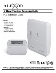
Installation and Setup Guide<br />
K0903V1 2/06 Rev. B<br />
ADEMCO 6160RF<br />
Keypad/Transceiver<br />
GENERAL INFORMATION<br />
The ADEMCO 6160RF keypad/transceiver is a combination unit that combines the functions of the following<br />
devices:<br />
• 6160 Alphanumeric Addressable Keypad<br />
• 5881H RF Receiver<br />
• 5800TM Transmitter Module<br />
The 6160RF Keypad/Transceiver may be used on any control panel that supports 5800 Series wireless devices<br />
(e.g., VISTA-10P, VISTA-15P, VISTA-20P).<br />
FEATURES<br />
• Supports wireless key transmitters (e.g.; 5804) and bi-directional transmitters (e.g.; 5804BD, 5828/5828V).<br />
• Supports wireless keys with high-security (encryption) capability (e.g.; 5804E).<br />
• Provides a nominal range of 200 feet' for RF transmitters (some transmitters have a shorter range).<br />
• Supports RF jam detection when the receiver is enabled.<br />
• Capable of sending status signals (Armed, Ready, etc.) to bi-directional units such as 5804BD, 5804BDV and<br />
5828/5828V.<br />
UL<br />
The following 5800 series transmitters are not intended for use in UL <strong>install</strong>ations: 5802, 5804, 5804BD, 5804BDV, 5804E,<br />
5814, 5816TEMP, 5819, 5819BRS, 5819WHS, 5828/5828V and 5850.<br />
INSTALLING THE 6160RF<br />
Locate the 6160RF in an area and at a height where<br />
it is convenient for user operation. The 6160RF must<br />
be at least 10 ft from the control panel to ensure<br />
proper operation of the RF receiver.<br />
Mounting and Wiring<br />
The 6160RF has terminal blocks for connection to<br />
power and data wires. Removing the keypad’s case<br />
back provides access to the terminal blocks.<br />
The 6160RF can be surface mounted directly to<br />
walls, or to a single- or double-gang electrical box.<br />
Follow these steps to mount and wire the keypad:<br />
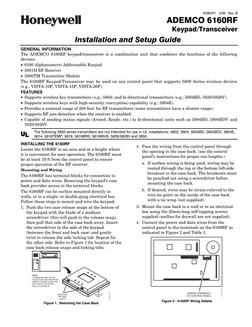
1. Push the two case release snaps at the bottom of<br />
the keypad with the blade of a medium<br />
screwdriver (this will push in the release snap),<br />
then pull that side of the case back away. Insert<br />
the screwdriver in the side of the keypad<br />
(between the front and back case) and gently<br />
twist to release the side locking tab. Repeat for<br />
the other side. Refer to Figure 1 for location of the<br />
case back release snaps and locking tabs.<br />
2. Pass the wiring from the control panel through<br />
the opening in the case back. (see the control<br />
panel’s instructions for proper run lengths.)<br />
a. If surface wiring is being used, wiring may be<br />
routed through the top or the bottom left-side<br />
breakout in the case back. The breakouts must<br />
be punched out using a screwdriver before<br />
mounting the case back.<br />
b. If desired, wires may be strain-relieved to the<br />
wire tie point on the inside of the case back<br />
with a tie wrap (not supplied).<br />
3. Mount the case back to a wall or to an electrical<br />
box using the 25mm-long self-tapping screws<br />
supplied (mollies for drywall are not supplied).<br />
4. Connect the power and data wires from the<br />
control panel to the terminals on the 6160RF as<br />
indicated in Figure 2 and Table 1.<br />
+<br />
Y + G<br />
+<br />
+<br />
+<br />
NOTE:<br />
TO REMOVE REAR COVER<br />
PUSH IN THE TWO MOUNTING<br />
SNAPS LOCATED ALONG THE<br />
BOTTOM OF THE KEYPAD<br />
AND LIFT COVER UP.<br />
MOUNTING<br />
RELEASE<br />
SNAPS<br />
LOCKING<br />
TAB<br />
Figure 1. Removing the Case Back<br />
6160RF-003-V1<br />
WIRING TERMINALS<br />
(TO CONTROL PANEL)<br />
Figure 2 - 6160RF Wiring Details<br />
6160RF-002-V1
Table 1 - Wiring Table<br />
Keypad Control Panel Wire Color<br />
G▼ (Data Out) Data In Green<br />
- -Aux Pwr (GND) Black<br />
+ +Aux Pwr Red<br />
▲Y (Data In) Data Out Yellow<br />
5. Reattach the keypad to the mounted case back.<br />
Attach the top of the keypad first, and then<br />
press the bottom section down until it snaps<br />
into place securely.<br />
6. Peel off protective film on the LED panel and<br />
<strong>install</strong> the keypad labels as required.<br />
APPLICATION GUIDELINES FOR THE 6160RF<br />
Use the following <strong>guide</strong>lines when planning an <strong>install</strong>ation:<br />
If… And… Then…<br />
This is the only<br />
transceiver on<br />
the system,<br />
There is another<br />
receiver or<br />
transceiver on<br />
the system,<br />
You want to use both<br />
the receiver and<br />
transmitter function<br />
on a single-partition<br />
system,<br />
You want to use only<br />
the transmitter<br />
function on a second<br />
partition,<br />
You want to use only<br />
the transmitter<br />
function on a singlepartition<br />
system,<br />
• Set the keypad to a device address assigned to the desired partition.*<br />
• Enable the receiver.<br />
• Program a system House ID in the control panel (this will enable the transmitter<br />
function).**<br />
• Set the wireless devices that will communicate with this 6160RF to the same<br />
system House ID.<br />
• Set the keypad to a device address assigned to the desired partition.*<br />
• Disable the receiver.<br />
• Program a DIFFERENT House ID in the 6160RF than is programmed in the control<br />
panel.*/ **<br />
• Set the wireless devices that will communicate with this 6160RF to the same<br />
House ID as the 6160RF.<br />
• Set the keypad to a device address assigned to the Partition 1.<br />
• Disable the receiver.<br />
• Program a House ID in the 6160RF that matches the system House ID<br />
programmed in the control panel.*<br />
• Set the wireless devices that will communicate with this 6160RF to the same<br />
House ID.<br />
Notes:<br />
* On VISTA-40 panels and above, wireless keypads (e.g., 5804BD) can only be used on a single partition. This<br />
partition is programmed in field 1*48, and must match the partition assigned to the 6160RF. Wireless keys can<br />
be used on more than one partition, using a House ID programmed in the 6160RF and the devices. In this case,<br />
the wireless keys must be assigned to the same partition as the 6160RF.<br />
** On VISTA-20P panels, the 6160RF will use the House ID programmed in the panel for the partition to which<br />
it is assigned. Wireless keypads can only be used on Partition 1.<br />
PROGRAMMING THE 6160RF<br />
Refer to the following procedure to program the 6160RF:<br />
STEP DESCRIPTION DISPLAY CHOICES<br />
1. Enter the program mode by pressing the [1] and [3] keys simultaneously<br />
for a few seconds within 60 seconds after applying power.<br />
2. (Keypad Address) Enter the two-digit keypad address. Press the [✻] key<br />
CON ADDRESS = XX 00-31<br />
to continue.<br />
Notes: (1) Refer to the control panel’s <strong>install</strong>ation instructions for the<br />
acceptable keypad addresses.<br />
(2) On the VISTA-40 and above the 6160RF’s partition assignment must<br />
match the RF keypad partition assignment programmed in field<br />
(1*48).<br />
3. (Receiver Enable) Enter [1] to enable, or [0] to disable Receiver. Enable<br />
the receiver if RF transmitters or wireless keypads are programmed into<br />
the control and no other receivers are enabled. Press the [✻] key to<br />
continue.<br />
RECEIVER<br />
ON [0= OFF]<br />
1= ON<br />
0 = OFF<br />
- 2 -
STEP DESCRIPTION DISPLAY CHOICES<br />
4. (Receiver Address) If receiver is enabled, enter the two-digit receiver<br />
REC ADDRESS= XX 00-30<br />
address. (01-30).<br />
Note: Refer to the control panel’s <strong>install</strong>ation instructions for the acceptable<br />
receiver addresses.<br />
Press the [✻] key to continue.<br />
5. (House ID) This prompt will only appear if the receiver is disabled. If the<br />
HOUSE ID = XX 00-31<br />
receiver is enabled the 6160RF will use the House ID programmed in<br />
the panel. Refer to Application Guidelines section when selecting a<br />
House ID.<br />
To program a House ID: Enter 01-31.<br />
To disable the transmitter: Enter 00<br />
Note: Each device that will receive status from the 6160RF must be set to the<br />
same House ID as the 6160RF (refer to Application Guidelines section).<br />
Press the [✻] key to continue.<br />
6. (Enable High Security Mode) Enter [1] to select High Security Mode.<br />
HIGH SECURITY<br />
1= Enable<br />
Note: If the High Security mode is enabled, the 6160RF will only recognize<br />
0 = Disable<br />
OFF [1] = ON<br />
encrypted devices. If this mode is disabled, the 6160RF will process<br />
commands both encrypted and non-encrypted devices. *<br />
Press the [✻] key to continue.<br />
7. (Disable High Security Devices) Press the [✻] key to skip this prompt<br />
and exit Program Mode.<br />
Notes: (1) The [✻] key must be pressed several times in order to save the<br />
programmed data.<br />
(2) If you need to disable encrypted devices, refer to the Disabling High<br />
Security Devices section.<br />
DISABLE HS DEV?<br />
NO [1] = YES<br />
1= YES<br />
0 = NO<br />
* When operating the system in High-Security mode, 5804BD wireless keys will still function. If you want the system to<br />
recognize only encrypted wireless devices, program only encrypted devices in the system.<br />
ACTIVATING HIGH SECURITY DEVICES<br />
This following procedure should be followed if using High-Security (encrypted) devices.<br />
STEP<br />
DESCRIPTION<br />
1. Follow the normal procedure for programming the device into the control panel (refer to the Installation<br />
Instructions for the device that you are programming). Exit out of Programming Mode.<br />
2. Put the control panel in Go/ No Go Test mode. (See the Installation Guide for the panel being <strong>install</strong>ed.)<br />
3. Follow the instructions supplied with each wireless device to enroll the device in High-security mode. After each<br />
device is enrolled the 6160RF will momentarily display “SECURITY DEVICE” along with the device number and<br />
its serial number.<br />
Note: The 6160RF will support a maximum of 8 devices. If you attempt to enroll additional devices the keypad will display<br />
“EXCEEDED NUMBER” “ALLOWED DEVICES”.<br />
DISABLING HIGH SECURITY DEVICES<br />
This mode gives you the ability to disable high security on all wireless keys that have been enrolled in the<br />
6160RF. This is particularly useful if a user loses a wireless key.<br />
!<br />
Once high-security (encrypted) devices have been disabled, they will only operate if the 6160RF is set to listen to both<br />
encrypted and non-encrypted devices (programming step 6, above). To completely disable the devices, they must be deleted<br />
from the control panel.<br />
STEP DESCRIPTION DISPLAY CHOICES<br />
1. After the keypad has been powered for at least 60 seconds hold<br />
CON ADDRESS=XX<br />
00-31<br />
down the [1] and [3] keys at the same time for 3 seconds. The<br />
current keypad address will be displayed. (You cannot change the<br />
keypad’s address at this point.) Press the [✻] key to continue.<br />
2. (Delete High Security Devices) Press the [1] key to remove all highsecurity<br />
(encrypted) devices. Press the [✻] key to continue.<br />
3. If YES was selected in Step 2 the unit will display a confirm<br />
request to delete the stored high security device. Press the [1] key<br />
to accept, followed by the [✻] key to exit the programming mode.<br />
DISABLE HS DEV?<br />
NO [1]=YES<br />
ARE YOU SURE?<br />
NO [1]=YES<br />
1= YES<br />
0 = NO<br />
1= YES<br />
0 = NO<br />
- 3 -
TROUBLESHOOTING<br />
The error messages listed in the following table cause the 6160RF to produce a single ding tone. The table<br />
describes the error messages and the corrective actions.<br />
Display Probable Cause Corrective Action<br />
Low Bat (with<br />
zone no.)<br />
Low battery in the wireless device.<br />
1. Replace the battery if the wireless transmitter has a replaceable battery.<br />
2. Replace the transmitter if the wireless transmitter does not have a<br />
replaceable battery.<br />
Open Ckt No data is being received from the control panel. Verify that the keypad ▲Y (yellow) wire is connected properly.<br />
Check 100<br />
Check 1xx*<br />
1. The control panel does not see the 6160RF<br />
Receiver, or the Receiver is not functioning.<br />
2. Another device on the keypad terminals is not<br />
communicating to the control panel.<br />
*xx= the device address of the receiver.<br />
SPECIFICATIONS<br />
Physical: 5-3/8” H x 7-3/8” W x 1-1/4” D<br />
(137mm x 187mm x 32mm)<br />
Wiring: Refer to Table 1<br />
Range: 200 ft (60.9 m) nominal<br />
Frequency: 345 MHz<br />
1a. Verify that the keypad ▲Y (yellow) and G▼ (green) wires are<br />
connected properly.<br />
1b. Verify that the control’s receiver address is correct.<br />
2. Verify the wiring connections between the control and all other devices.<br />
Current: Standby 50mA<br />
Backlighting on and<br />
Sounder on<br />
150mA<br />
Display: 2 x 16 alphanumeric supertwist LCD, backlit<br />
Sounder: Tone Generator Integrated Circuit. (fire alarm is loud pulsing tone;<br />
burglary/audible panic alarm is continuous tone)<br />
FOR DETAILS ON THE LIMITATIONS OF THE ENTIRE ALARM SYSTEM, REFER TO THE INSTALLATION AND SETUP GUIDE FOR THE CONTROL PANEL BEING<br />
INSTALLED IN CONJUCTION WITH THIS DEVICE.<br />
FCC STATEMENT & INDUSTRY CANADA STATEMENT<br />
This device complies with Part 15 of the FCC rules and RSS210 of Industry Canada. Operation is subject to the following two conditions: (1) This device may not<br />
cause harmful interference, and (2) This device must accept any interference received, including interference that may cause undesired operation.<br />
Federal Communications Commission (FCC) Part 15 Statement<br />
This equipment has been tested to FCC requirements and has been found acceptable for use. The FCC requires the following statement for your information:<br />
This equipment generates and uses radio frequency energy and if not <strong>install</strong>ed and used properly, that is, in strict accordance with the manufacturer's instructions, may<br />
cause interference to radio and television reception. It has been type tested and found to comply with the limits for a Class B computing device in accordance with the<br />
specifications in Part 15 of FCC Rules, which are designed to provide reasonable protection against such interference in a residential <strong>install</strong>ation. However, there is no<br />
guarantee that interference will not occur in a particular <strong>install</strong>ation. If this equipment does cause interference to radio or television reception, which can be determined<br />
by turning the equipment off and on, the user is encouraged to try to correct the interference by one or more of the following measures:<br />
• If using an indoor antenna, have a quality outdoor antenna <strong>install</strong>ed.<br />
• Reorient the receiving antenna until interference is reduced or eliminated.<br />
• Move the radio or television receiver away from the receiver/control.<br />
• Move the antenna leads away from any wire runs to the receiver/control.<br />
• Plug the receiver/control into a different outlet so that it and the radio or television receiver are on different branch circuits<br />
If necessary, the user should consult the dealer or an experienced radio/television technician for additional suggestions. The user or <strong>install</strong>er may find the following<br />
booklet prepared by the Federal Communications Commission helpful: "Interference Handbook." This booklet is available from the U.S. Government Printing Office,<br />
Washington, DC 20402.<br />
The user shall not make any changes or modifications to the equipment unless authorized by the Installation Instructions or User's Manual. Unauthorized changes or<br />
modifications could void the user's authority to operate the equipment.<br />
LIMITED WARRANTY<br />
Honeywell International <strong>Inc</strong>., acting through its Security & Custom Electronics business ("Seller") 165 Eileen Way, Syosset, New York 11791, warrants its products to be<br />
in conformance with its own plans and specifications and to be free from defects in materials and workmanship under normal use and service for 24 months from the<br />
date stamp control on the product or, for products not having an Ademco date stamp, for 12 months from date of original purchase unless the <strong>install</strong>ation instructions or<br />
catalog sets forth a shorter period, in which case the shorter period shall apply. Seller's obligation shall be limited to repairing or replacing, at its option, free of charge<br />
for materials or labor, any product which is proved not in compliance with Seller's specifications or proves defective in materials or workmanship under normal use and<br />
service. Seller shall have no obligation under this Limited Warranty or otherwise if the product is altered or improperly repaired or serviced by anyone other than Ademco<br />
factory service. For warranty service, return product transportation prepaid, to Factory Service, 165 Eileen Way, Syosset, New York 11791.<br />
THERE ARE NO WARRANTIES, EXPRESS OR IMPLIED, OF MERCHANTABILITY, OR FITNESS FOR A PARTICULAR PURPOSE OR OTHERWISE, WHICH EXTEND<br />
BEYOND THE DESCRIPTION ON THE FACE HEREOF. IN NO CASE SHALL SELLER BE LIABLE TO ANYONE FOR ANY CONSEQUENTIAL OR INCIDENTAL DAMAGES<br />
FOR BREACH OF THIS OR ANY OTHER WARRANTY, EXPRESS OR IMPLIED, OR UPON ANY OTHER BASIS OF LIABILITY WHATSOEVER, EVEN IF THE LOSS OR<br />
DAMAGE IS CAUSED BY THE SELLER'S OWN NEGLIGENCE OR FAULT.<br />
Seller does not represent that the products it sells may not be compromised or circumvented; that the products will prevent any personal injury or property loss by<br />
burglary, robbery, fire or otherwise; or that the products will in all cases provide adequate warning or protection. Customer understands that a properly <strong>install</strong>ed and<br />
maintained alarm may only reduce the risk of a burglary, robbery, fire or other events occurring without providing an alarm, but it is not insurance or a guarantee that<br />
such will not occur or that there will be no personal injury or property loss as a result. CONSEQUENTLY, SELLER SHALL HAVE NO LIABILITY FOR ANY PERSONAL<br />
INJURY, PROPERTY DAMAGE OR OTHER LOSS BASED ON A CLAIM THE PRODUCT FAILED TO GIVE WARNING. HOWEVER, IF SELLER IS HELD LIABLE, WHETHER<br />
DIRECTLY OR INDIRECTLY, FOR ANY LOSS OR DAMAGE ARISING UNDER THIS LIMITED WARRANTY OR OTHERWISE, REGARDLESS OF CAUSE OR ORIGIN,<br />
SELLER'S MAXIMUM LIABILITY SHALL NOT IN ANY CASE EXCEED THE PURCHASE PRICE OF THE PRODUCT, WHICH SHALL BE THE COMPLETE AND EXCLUSIVE<br />
REMEDY AGAINST SELLER. This warranty replaces any previous warranties and is the only warranty made by Seller on this product. No increase or alteration, written or<br />
verbal, of the obligations of this Limited Warranty is authorized.<br />
‡K0903V1?Š<br />
K0903V1 2/06 Rev. B<br />
165 Eileen Way, Syosset, New York 11791<br />
Copyright © 2006 Honeywell International <strong>Inc</strong>.<br />
www.honeywell.com/security