SB-GA8-2009-38 - GippsAero
SB-GA8-2009-38 - GippsAero
SB-GA8-2009-38 - GippsAero

Create successful ePaper yourself
Turn your PDF publications into a flip-book with our unique Google optimized e-Paper software.
PO Box 881, Morwell, Victoria <strong>38</strong>40, Australia<br />
Ph + 61 (0) 3 5172 1200<br />
Fax + 61 (0) 3 5172 1201<br />
www.gippsaero.com<br />
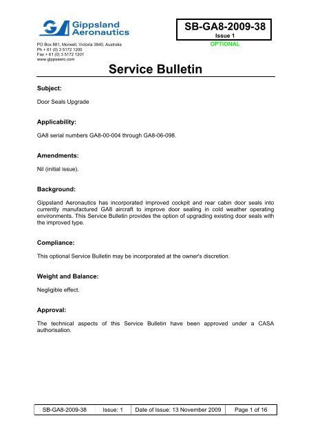
Subject:<br />
Door Seals Upgrade<br />
Service Bulletin<br />
<strong>SB</strong>-<strong>GA8</strong>-<strong>2009</strong>-<strong>38</strong><br />
Issue 1<br />
OPTIONAL<br />
Applicability:<br />
<strong>GA8</strong> serial numbers <strong>GA8</strong>-00-004 through <strong>GA8</strong>-06-098.<br />
Amendments:<br />
Nil (initial issue).<br />
Background:<br />
Gippsland Aeronautics has incorporated improved cockpit and rear cabin door seals into<br />
currently manufactured <strong>GA8</strong> aircraft to improve door sealing in cold weather operating<br />
environments. This Service Bulletin provides the option of upgrading existing door seals with<br />
the improved type.<br />
Compliance:<br />
This optional Service Bulletin may be incorporated at the owner's discretion.<br />
Weight and Balance:<br />
Negligible effect.<br />
Approval:<br />
The technical aspects of this Service Bulletin have been approved under a CASA<br />
authorisation.<br />
<strong>SB</strong>-<strong>GA8</strong>-<strong>2009</strong>-<strong>38</strong> Issue: 1 Date of Issue: 13 November <strong>2009</strong> Page 1 of 16
Parts:<br />
Item Part Number Description Qty<br />
1 <strong>GA8</strong>-251019-11 OPENING SEAL ASSEMBLY (Cockpit Door, LH) 1<br />
2 <strong>GA8</strong>-251019-12 OPENING SEAL ASSEMBLY (Cockpit Door, RH) 1<br />
3 <strong>GA8</strong>-251029-25 LOWER SEAL (Cockpit Door, LH) 1<br />
4 <strong>GA8</strong>-251029-26 LOWER SEAL (Cockpit Door, RH) 1<br />
5 <strong>GA8</strong>-251029-27 DOOR SEAL (Cockpit Door, LH) 1<br />
6 <strong>GA8</strong>-251029-28 DOOR SEAL (Cockpit Door, RH) 1<br />
7 <strong>GA8</strong>-252043-11 OPENING SEAL ASSEMBLY (Rear Cabin Door) 1<br />
8 <strong>GA8</strong>-252025-81 CARGO DOOR FWD TRIM 1<br />
9 <strong>GA8</strong>-252053-25 DOOR FORWARD SEAL (Rear Cabin Door) 1<br />
10 <strong>GA8</strong>-252053-27 DOOR AFT SEAL (Rear Cabin Door) 1<br />
11 <strong>GA8</strong>-252053-29 DOOR UPPER SEAL (Rear Cabin Door) 1<br />
12 <strong>GA8</strong>-252053-31 DOOR LOWER SEAL (Rear Cabin Door) 1<br />
13 <strong>GA8</strong>-521022-145 DOOR RAMP 1<br />
14 <strong>GA8</strong>-521022-191 SEAL RETAINER 1<br />
15 <strong>GA8</strong>-521022-193 PIVOT ARM SEAL 1<br />
16 <strong>GA8</strong>-521022-195 ARM SEAL BLOCK 1<br />
17 <strong>GA8</strong>-521022-203 INTERIOR PANEL AFT RETAINER 1<br />
18 MS20426AD3-3.5 COUNTERSUNK RIVET 8<br />
19 Cherry CCR264CS3-4 NUTPLATE ("PULL THROUGH") RIVET 2<br />
20 6x1/2 PTAG SELF-TAPPING SCREW (Painted Grey Head) 4<br />
21 Dow Corning Silastic<br />
747 Silicone RTV<br />
SEALANT/ADHESIVE<br />
22 A3236-012-935 COUNTERSUNK WASHER (Painted Grey) 4<br />
23 A6195-6Z1D TINNERMAN NUTPLATE 4<br />
24 S1022Z6-8 COUNTERSUNK SCREW (Painted Grey Head) 4<br />
25 TLPD321 POP RIVET 7<br />
A/R<br />
<strong>SB</strong>-<strong>GA8</strong>-<strong>2009</strong>-<strong>38</strong> Issue: 1 Date of Issue: 13 November <strong>2009</strong> Page 2 of 16
Parts Availability:<br />
Gippsland Aeronautics participation is limited to the supply of parts, including freight, at the<br />
owner's expense.<br />
Parts may be sourced locally or a kit can be obtained directly from Gippsland Aeronautics<br />
(Part Number <strong>SB</strong>-<strong>GA8</strong>-<strong>2009</strong>-<strong>38</strong>-1).<br />
Tel.: +61 03 5172 1208<br />
Fax.: +61 03 5172 1237<br />
Email: spares@gippsaero.com<br />
Labour:<br />
Approximately 8 hours should be allocated for completing the work detailed in this Service<br />
Bulletin. This does not include curing times of sealants/adhesives or primers and topcoats,<br />
for which manufacturer instructions should be consulted.<br />
<strong>SB</strong>-<strong>GA8</strong>-<strong>2009</strong>-<strong>38</strong> Issue: 1 Date of Issue: 13 November <strong>2009</strong> Page 3 of 16
Instructions:<br />
NOTES<br />
Prior to installation of new seals, ensure all traces of any previous<br />
sealant/adhesive compound are removed from attachment surfaces<br />
on the aircraft using a plastic spatula and Prepsol (or equivalent) on a<br />
cloth. Prepare attachment surfaces of both the aircraft and the new<br />
seals by lightly abrading with a scouring pad (such as Scotch-Brite)<br />
and cleaning with acetone (or equivalent).<br />
If removal or damage to corrosion protection or paint occurs during<br />
removal of old seals, treat in accordance with the following procedure<br />
prior to installation of new seals:<br />
1. Lightly abrade surface using scouring pads (such as<br />
Scotch-Brite) or fine sandpaper where necessary.<br />
Abrasion by hand is to be in a crosshatch pattern.<br />
This light etching improves the adherence of primer<br />
to the surface of the material. Thoroughly clean<br />
surface using Prepsol (or equivalent) after abrasion.<br />
2. Prepare and apply zinc chromate (or equivalent)<br />
primer to aluminium alloy surfaces, or Durepon P14<br />
epoxy zinc phosphate (or equivalent) primer to steel<br />
surfaces, in accordance with manufacturer<br />
instructions.<br />
3. Prepare and apply two to three coats of<br />
polyurethane two pack topcoat of the appropriate<br />
colour to primed aluminium alloy or steel surfaces,<br />
in accordance with manufacturer instructions.<br />
4. Allow curing in accordance with topcoat<br />
manufacturer instructions.<br />
When installing new seals, ensure seals are retained in their correct<br />
positions until cured using masking tape or clips.<br />
Manufacturer recommendations should be referred to for cure times<br />
and surface preparation procedure for Dow Corning Silastic 747<br />
Silicone RTV Adhesive/Sealant.<br />
<strong>SB</strong>-<strong>GA8</strong>-<strong>2009</strong>-<strong>38</strong> Issue: 1 Date of Issue: 13 November <strong>2009</strong> Page 4 of 16
Cockpit Doors<br />
Complete the following procedure for both the left and right cockpit doors:<br />
1. Remove the pinchweld seal from around the cockpit door opening, retaining the<br />
windscreen pillar trim angle in its original location on the cockpit frame using masking<br />
tape.<br />
2. Fasten the windscreen pillar trim angle into its original location onto the cockpit frame<br />
using Dow Corning Silastic 747 Silicone RTV Adhesive/Sealant as the bonding agent.<br />
NOTE<br />
Prior to installation of new seals, ensure all traces of any previous<br />
sealant/adhesive compound are removed from attachment surfaces<br />
on the aircraft using a plastic spatula and Prepsol (or equivalent) on a<br />
cloth. Prepare attachment surfaces of both the aircraft and the new<br />
seals by lightly abrading with a scouring pad (such as Scotch-Brite)<br />
and cleaning with acetone (or equivalent).<br />
3. Locate and install the opening seal assembly (left hand side P/N <strong>GA8</strong>-251019-11, right<br />
hand side P/N <strong>GA8</strong>-251019-12) over the door seal angles from the lower forward to<br />
lower aft corners of the door opening, using Dow Corning Silastic 747 Silicone RTV<br />
Adhesive/Sealant as the bonding agent injected into the channel between the attach<br />
flange and D section of the seal, similar to the installation shown in Figures 1, 2 and 5.<br />
Locate and bond the seal assembly join into the upper aft corner of the door opening<br />
and the trimmed end sections flush against the outboard face of the door sill, and<br />
ensure there is a 1/8" gap between the seal ends and the bottom of the door sill.<br />
Locate the trimmed section of seal attach flange along the aft side of the door opening<br />
to clear the door striker plate, and ensure that the striker plate door locking surface is<br />
free of adhesive and there is no fouling of the door latch or locking ability. Trim the<br />
edge of the seal around the striker plate as required. Smooth the seal attach flange to<br />
remove wrinkles.<br />
4. Locate and install the lower seal (left hand side P/N <strong>GA8</strong>-251029-25, right hand side<br />
P/N <strong>GA8</strong>-251029-26) 1/4" from the top of the door sill between the door opening seal<br />
assembly, using Dow Corning Silastic 747 Silicone RTV Adhesive/Sealant as the<br />
bonding agent, similar to the installation shown in Figure 1.<br />
5. Carefully remove the P section seal from the bottom of the cockpit door and remove<br />
any adhesive remnants using a plastic spatula and Prepsol (or equivalent) on a cloth.<br />
6. Locate and install the door seal (left hand side P/N <strong>GA8</strong>-251029-27, right hand side<br />
P/N <strong>GA8</strong>-251029-28) approximately 3/8” from the bottom edge of the door, using Dow<br />
Corning Silastic 747 Silicone RTV Adhesive/Sealant as the bonding agent, ensuring<br />
that the door seal mates with the lower seal when the door is closed, similar to the<br />
installation shown in Figure 3.<br />
<strong>SB</strong>-<strong>GA8</strong>-<strong>2009</strong>-<strong>38</strong> Issue: 1 Date of Issue: 13 November <strong>2009</strong> Page 5 of 16
7. Figures 1 to 5 show various aspects of the installation of the new cockpit door seals<br />
(right hand side shown).<br />
UP<br />
FWD<br />
LOWER SEAL<br />
(<strong>GA8</strong>-251029-26) 1/4"<br />
OPENING SEAL ASSEMBLY<br />
(<strong>GA8</strong>-251019-12)<br />
Figure 1: New seals installed in the lower section of the<br />
door opening (right hand side shown).<br />
UP<br />
FWD<br />
OPENING SEAL ASSEMBLY<br />
(<strong>GA8</strong>-251019-12)<br />
Figure 2: New seals installed in the upper section of the<br />
door opening (right hand side shown).<br />
APPROX.<br />
3/8"<br />
DOOR SEAL<br />
(<strong>GA8</strong>-251029-28)<br />
UP<br />
FWD<br />
Figure 3: New seal installed on the inside of the door to<br />
mate with the seal installed on the outboard face of the sill<br />
in the door opening (right hand side shown).<br />
<strong>SB</strong>-<strong>GA8</strong>-<strong>2009</strong>-<strong>38</strong> Issue: 1 Date of Issue: 13 November <strong>2009</strong> Page 6 of 16
LOWER SEAL<br />
(<strong>GA8</strong>-251029-26)<br />
DOOR SEAL<br />
(<strong>GA8</strong>-251029-28)<br />
UP<br />
FWD<br />
Figure 4: New seals installed in the lower door opening<br />
and on the inside of the door (right hand side shown).<br />
Note the alignment of the seal on the door with the seal<br />
along the outboard face of the sill in the door opening.<br />
OPENING SEAL ASSEMBLY<br />
(<strong>GA8</strong>-251019-12)<br />
UP<br />
FWD<br />
LOWER SEAL<br />
(<strong>GA8</strong>-251029-26)<br />
Figure 5: New seals installed in the door opening (right<br />
hand side shown).<br />
<strong>SB</strong>-<strong>GA8</strong>-<strong>2009</strong>-<strong>38</strong> Issue: 1 Date of Issue: 13 November <strong>2009</strong> Page 7 of 16
Rear Cabin Door<br />
1. Unscrew and remove the three screws securing the forward door mount fairing.<br />
Carefully cut through the sealant around the fairing and remove the fairing.<br />
2. Carefully remove the rear cargo door from the aircraft by unscrewing and removing the<br />
three bolts on each of the bottom and top door slide mounts, and if required<br />
unscrewing and removing the bolt attaching the forward door mount to the slider.<br />
3. Remove the adhesive plugs at the bottom and top aft corners of the door (refer to<br />
Figure 6).<br />
4. Unscrew and remove the two screws securing the inside door latch cover, and the two<br />
screws securing the latch support. If necessary (refer to note following Step 5), remove<br />
the adhesive securing the cover to the support at the top aft corner, and remove the<br />
cover and the support.<br />
NOTE<br />
The door latch is spring loaded and held in place by the latch support.<br />
5. Drill out and remove the five pop rivets securing the upper aft trim angle and remove<br />
the trim angle. Drill out and remove the five pop rivets securing the lower aft trim angle<br />
and remove the trim angle. Figure 6 shows the lower two rivets securing the lower trim<br />
angle.<br />
NOTE<br />
Removal of the cover and support, including the adhesive securing<br />
the top aft corner of the cover, is not required if the trim angle can be<br />
removed from underneath the lower leg of the support.<br />
LOWER AFT TRIM ANGLE<br />
DRILL OUT AND REMOVE<br />
RIVETS (10 PLACES)<br />
REMOVE ADHESIVE<br />
FWD<br />
Stbd.<br />
Figure 6: Rear cabin door (prior to upgrading).<br />
6. Carefully remove the aft door seal and remove any adhesive remnants using a plastic<br />
spatula and Prepsol (or equivalent) on a cloth.<br />
<strong>SB</strong>-<strong>GA8</strong>-<strong>2009</strong>-<strong>38</strong> Issue: 1 Date of Issue: 13 November <strong>2009</strong> Page 8 of 16
7. Drill out and remove the seven pop rivets securing the horizontal interior panel<br />
retaining angle below the windows. Remove the horizontal interior panel retaining<br />
angle.<br />
8. Unscrew and remove the nine countersunk screws along the lower edge and the four<br />
screws along the forward edge of the door interior panel.<br />
9. Carefully remove the interior panel.<br />
NOTE<br />
A silicone sealant was used during production to assist in securing<br />
the interior panel to the door structure.<br />
10. If the installed pivot arm seal is not manufactured from the currently used VSR3<br />
silicone baffle seal material (coloured orange per Figure 7), complete Steps 11 and 12.<br />
If there is no pivot arm seal installed, continue from Step 12. Otherwise continue from<br />
Step 13.<br />
11. If a pivot arm seal is installed, drill out the blind rivets securing the pivot arm seal<br />
retainer and remove the retainer. Then remove the existing pivot arm seal around the<br />
forward pivot arm assembly, and remove any adhesive remnants using a plastic<br />
spatula and Prepsol (or equivalent) on a cloth.<br />
CHERRY<br />
NUTPLATE RIVET<br />
PIVOT ARM SEAL<br />
(<strong>GA8</strong>-521022-193)<br />
SEAL RETAINER<br />
(<strong>GA8</strong>-521022-191)<br />
UP<br />
SEALANT BEAD<br />
FWD<br />
Figure 7: Installation of new pivot arm seal.<br />
12. Ensure the door handle is in the closed position and locate new pivot arm seal<br />
(<strong>GA8</strong>-521022-193) for best sealing. Reinstall the seal retainer (P/N <strong>GA8</strong>-521022-191)<br />
using two CCR264CS3-4 blind rivets. If required, locate the seal retainer over the pivot<br />
arm seal and drill a 3/32" diameter (#40) hole through the retainer holes, the seal and<br />
the pivot arm before installing the nutplate rivets. Apply a bead of Dow Corning Silastic<br />
747 Silicone RTV Adhesive/Sealant along the outer middle edge of the seal retainer.<br />
Figure 7 shows the completed installation of the new seal around the pivot arm.<br />
13. If the installed arm seal block has deteriorated and requires replacement, complete<br />
Step 14. Otherwise continue from Step 15.<br />
<strong>SB</strong>-<strong>GA8</strong>-<strong>2009</strong>-<strong>38</strong> Issue: 1 Date of Issue: 13 November <strong>2009</strong> Page 9 of 16
14. Remove the arm seal block inside the forward pivot arm assembly, and remove any<br />
adhesive remnants using a plastic spatula and Prepsol (or equivalent) on a cloth. Install<br />
new arm seal block (<strong>GA8</strong>-521022-195) using grease or sealant/adhesive as required.<br />
Figure 8 shows the installation of the new arm seal block.<br />
UP<br />
FWD<br />
ARM SEAL BLOCK<br />
(<strong>GA8</strong>-521022-195)<br />
FORWARD PIVOT<br />
ARM ASSEMBLY<br />
Figure 8: Installation of the new arm seal block.<br />
15. Carefully remove the existing lower door seal and remove any adhesive remnants<br />
using a plastic spatula and Prepsol (or equivalent) on a cloth.<br />
NOTE<br />
Prior to installation of new seals, ensure all traces of any previous<br />
sealant/adhesive compound are removed from attachment surfaces<br />
on the aircraft using a plastic spatula and Prepsol (or equivalent) on a<br />
cloth. Prepare attachment surfaces of both the aircraft and the new<br />
seals by lightly abrading with a scouring pad (such as Scotch-Brite)<br />
and cleaning with acetone (or equivalent).<br />
<strong>SB</strong>-<strong>GA8</strong>-<strong>2009</strong>-<strong>38</strong> Issue: 1 Date of Issue: 13 November <strong>2009</strong> Page 10 of 16
16. Locate and install the lower door seal (P/N <strong>GA8</strong>-252053-31) along the lower edge of<br />
the door starting at 1/4" forward past the forward vertical post to 5/16" past the aft<br />
vertical post, with the bent leg portion of the seal facing outboard and the bulb part of<br />
the seal facing inboard, using Dow Corning Silastic 747 Silicone RTV Adhesive/Sealant<br />
as the bonding agent, similar to the installation shown in Figure 12. Cut 1/4" diameter<br />
holes through the leg of the seal corresponding to the door frame drain holes, and 1/2"<br />
diameter holes in the leg of the seal around the holes in the door frame for installing the<br />
lower door slide mount, similar to the installation shown in Figure 9.<br />
DOOR LOWER SEAL<br />
(<strong>GA8</strong>-252053-31)<br />
UP<br />
FWD<br />
Figure 9: Holes in the leg of the seal around the holes in<br />
the door frame for installing the lower door slide mount.<br />
17. Locate and install the aft door seal (P/N <strong>GA8</strong>-252053-27) along the aft edge of the<br />
door, ensuring the D section is flush against the outboard face of the door and the<br />
3/32" diameter holes near the ends of the seal face inboard, using Dow Corning<br />
Silastic 747 Silicone RTV Adhesive/Sealant as the bonding agent, similar to the<br />
installation shown in Figure 11.<br />
18. Locate and install the forward door seal (P/N <strong>GA8</strong>-252053-25) along the forward edge<br />
of the door, ensuring the bulb part of the P section is flush against the outboard face of<br />
the door and the 3/32" diameter holes near the ends of the seal face inboard, using<br />
Dow Corning Silastic 747 Silicone RTV Adhesive/Sealant as the bonding agent, similar<br />
to the installation shown in Figure 12.<br />
19. Locate and install the upper door seal (P/N <strong>GA8</strong>-252053-29) along the upper edge of<br />
the door starting at 1/4" forward past the forward vertical post to 5/16" past the aft<br />
vertical post, with the bulb part of the seal facing inboard and overhanging flush against<br />
the inboard edge of the top of the door and the 3/32" diameter holes near the ends of<br />
the seal facing down, using Dow Corning Silastic 747 Silicone RTV Adhesive/Sealant<br />
as the bonding agent, similar to the installation shown in Figure 11.<br />
20. Trim the lower edge of the interior panel as necessary to conform to the edge of the<br />
new lower door seal when the panel is installed.<br />
21. Temporarily secure the interior panel onto the door frame and locate the new interior<br />
panel aft retainer (<strong>GA8</strong>-521022-203) onto the interior panel orientated with the<br />
chamfered corner of the retainer at the lower aft corner of the panel (Figure 10 shows<br />
the location and orientation of the new interior panel aft retainer). Mark the four 5/16"<br />
diameter holes from the retainer onto the interior panel. Drill 3/32" diameter (#40) holes<br />
through the interior panel and door frame at the centre of the four marked holes.<br />
<strong>SB</strong>-<strong>GA8</strong>-<strong>2009</strong>-<strong>38</strong> Issue: 1 Date of Issue: 13 November <strong>2009</strong> Page 11 of 16
22. Ensuring the retainer is correctly positioned, locate and mark the hole corresponding to<br />
the lower aft corner of the door latch cover onto the retainer. Remove the retainer from<br />
the door and drill a 1/4" diameter hole through the retainer at the marked location.<br />
23. Remove the interior panel from the door and drill out the four 3/32" diameter holes in<br />
the interior panel to 5/16" diameter.<br />
DOOR LATCH COVER<br />
DOOR AFT SEAL<br />
(<strong>GA8</strong>-252053-27)<br />
INTERIOR PANEL AFT RETAINER<br />
(<strong>GA8</strong>-521022-203)<br />
UP<br />
FWD<br />
OPENING SEAL ASSEMBLY<br />
(<strong>GA8</strong>-252043-11)<br />
DOOR LOWER SEAL<br />
(<strong>GA8</strong>-252053-31)<br />
Figure 10: Installation of new rear cabin door seals and<br />
interior panel aft retainer.<br />
24. Using a neutral cure, non-corrosive silicone sealant/adhesive as the bonding agent,<br />
bond the interior panel to the door structure at all metallic contact points around the<br />
frame and on internal structure.<br />
25. Secure the interior panel to the lower and forward side cargo door frame using original<br />
hardware.<br />
26. Reinstall the horizontal interior panel retaining angle and install the new interior panel<br />
aft retainer over the panel using four A3236-012-935 countersunk washers and<br />
S1022Z6-8 countersunk screws in the lower holes.<br />
27. Reinstall the door latch support and cover (over the new interior panel retainer) using<br />
original hardware, ensuring the latch is restored to its original location in the latch<br />
support, and using (preferably grey colour) neutral cure, non-corrosive silicone<br />
sealant/adhesive to bond the cover to the support at the aft upper corner. Ensure all<br />
remnants of previously used sealant are removed.<br />
28. Remove the pinchweld seals from the upper and forward edges of the rear cabin door<br />
opening. Remove the trim angle held in place by the pinchweld seal along the forward<br />
edge of the door opening.<br />
29. Unscrew and remove the left hand side wall interior panels as required to access inside<br />
the forward cabin door opening pillar.<br />
30. Locate the new cargo door forward trim angle (P/N <strong>GA8</strong>-252025-81) with the line of<br />
holes in the trim angle aligned with the line of rivets securing the door seal angle to the<br />
pillar.<br />
<strong>SB</strong>-<strong>GA8</strong>-<strong>2009</strong>-<strong>38</strong> Issue: 1 Date of Issue: 13 November <strong>2009</strong> Page 12 of 16
31. Back drill the four 5/32 inch diameter holes from the trim angle through the door seal<br />
angle and pillar.<br />
32. Install an A6195-6Z1D Tinnerman nutplate on the inside of the pillar for each 5/32 inch<br />
diameter hole using MS20426AD3-3.5 countersunk rivets.<br />
33. Reinstall the left hand side wall interior panels and install the trim angle over the edges<br />
of the interior panels using four 6x1/2 PTAG self-tapping screws.<br />
34. Locate and install the opening seal assembly (P/N <strong>GA8</strong>-252043-11) over the door seal<br />
angles from the forward lower to aft upper corners of the door opening, using Dow<br />
Corning Silastic 747 Silicone RTV Adhesive/Sealant as the bonding agent injected into<br />
the channel between the attach flange and D section of the seal, similar to the<br />
installation shown in Figure 13. Locate and bond the seal assembly join into the upper<br />
forward corner of the door opening, and ensure there is a 1/8" gap between the forward<br />
lower end of the seal and the floor. Trim minimal amounts from the seal attach flange to<br />
allow ease of installation of the seal around the grab handle fasteners, similar to the<br />
installation shown in Figure 14. Smooth the seal attach flange as necessary to remove<br />
wrinkles.<br />
35. Reinstall cargo door using existing hardware, replacing hardware as necessary with the<br />
same type as originally used.<br />
36. Reinstall forward door mount fairing using original hardware and applying a bead of<br />
Dinitrol 410 UV sealant/adhesive around the base of the fairing except for the last two<br />
inches from the lower forward edge to allow for water drainage.<br />
37. Unscrew and remove the existing door ramp and install new door ramp (P/N<br />
<strong>GA8</strong>-521022-145) using existing hardware. Figure 15 shows the correct installation of<br />
the new door ramp.<br />
<strong>38</strong>. Figures 10 to 15 show various aspects of the installation of the new cabin door seals.<br />
UP<br />
FWD<br />
DOOR UPPER SEAL<br />
(<strong>GA8</strong>-252053-29)<br />
DOOR AFT SEAL<br />
(<strong>GA8</strong>-252053-27)<br />
Figure 11: Installation of the new upper and aft rear cabin<br />
door seals.<br />
<strong>SB</strong>-<strong>GA8</strong>-<strong>2009</strong>-<strong>38</strong> Issue: 1 Date of Issue: 13 November <strong>2009</strong> Page 13 of 16
DOOR FORWARD SEAL<br />
(<strong>GA8</strong>-252053-25)<br />
DOOR LOWER SEAL<br />
(<strong>GA8</strong>-252053-31)<br />
UP<br />
PORT<br />
Figure 12: Installation of the new lower and forward cabin<br />
door seals.<br />
PORT<br />
DOOR UPPER SEAL<br />
(<strong>GA8</strong>-252053-29)<br />
FWD<br />
DOOR AFT SEAL<br />
(<strong>GA8</strong>-252053-27)<br />
CARGO DOOR FWD TRIM<br />
(<strong>GA8</strong>-252025-81)<br />
OPENING SEAL ASSEMBLY<br />
(<strong>GA8</strong>-252043-11)<br />
Figure 13: Installation of the new upper and aft cabin<br />
door seals and cabin door opening seal assembly.<br />
UP<br />
FWD<br />
GRAB HANDLE<br />
OPENING SEAL ASSEMBLY<br />
(<strong>GA8</strong>-252043-11)<br />
Figure 14: Trimming of the opening seal attach flange<br />
around the grab handle fasteners.<br />
<strong>SB</strong>-<strong>GA8</strong>-<strong>2009</strong>-<strong>38</strong> Issue: 1 Date of Issue: 13 November <strong>2009</strong> Page 14 of 16
UP<br />
FWD<br />
DOOR RAMP<br />
(<strong>GA8</strong>-521022-145)<br />
Figure 15: Installation of the new door ramp.<br />
Documentation:<br />
Update aircraft log book to reflect incorporation of this Service Bulletin.<br />
Compliance Notice:<br />
Complete the Document Compliance Notice and return to Gippsland Aeronautics by fax or<br />
mail.<br />
<strong>SB</strong>-<strong>GA8</strong>-<strong>2009</strong>-<strong>38</strong> Issue: 1 Date of Issue: 13 November <strong>2009</strong> Page 15 of 16
This page has intentionally been left blank.<br />
<strong>SB</strong>-<strong>GA8</strong>-<strong>2009</strong>-<strong>38</strong> Issue: 1 Date of Issue: 13 November <strong>2009</strong> Page 16 of 16