SB-GA8-2004-14 - GippsAero
SB-GA8-2004-14 - GippsAero
SB-GA8-2004-14 - GippsAero
Create successful ePaper yourself
Turn your PDF publications into a flip-book with our unique Google optimized e-Paper software.
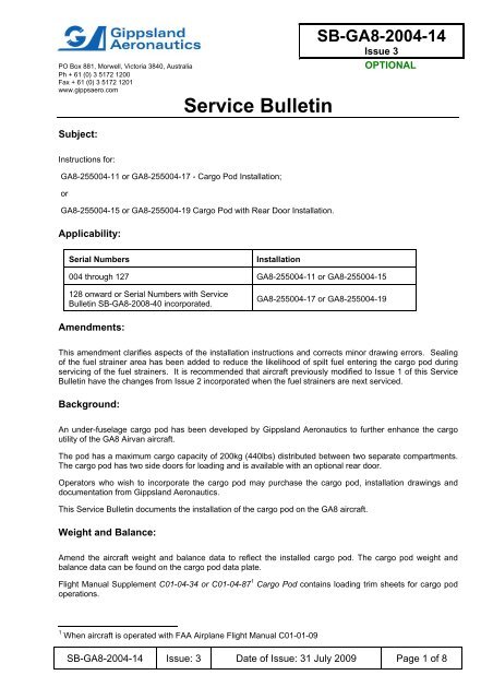
PO Box 881, Morwell, Victoria 3840, AustraliaPh + 61 (0) 3 5172 1200Fax + 61 (0) 3 5172 1201www.gippsaero.comSubject:Service Bulletin<strong>SB</strong>-<strong>GA8</strong>-<strong>2004</strong>-<strong>14</strong>Issue 3OPTIONALInstructions for:<strong>GA8</strong>-255004-11 or <strong>GA8</strong>-255004-17 - Cargo Pod Installation;or<strong>GA8</strong>-255004-15 or <strong>GA8</strong>-255004-19 Cargo Pod with Rear Door Installation.Applicability:Serial NumbersInstallation004 through 127 <strong>GA8</strong>-255004-11 or <strong>GA8</strong>-255004-15128 onward or Serial Numbers with ServiceBulletin <strong>SB</strong>-<strong>GA8</strong>-2008-40 incorporated.<strong>GA8</strong>-255004-17 or <strong>GA8</strong>-255004-19Amendments:This amendment clarifies aspects of the installation instructions and corrects minor drawing errors. Sealingof the fuel strainer area has been added to reduce the likelihood of spilt fuel entering the cargo pod duringservicing of the fuel strainers. It is recommended that aircraft previously modified to Issue 1 of this ServiceBulletin have the changes from Issue 2 incorporated when the fuel strainers are next serviced.Background:An under-fuselage cargo pod has been developed by Gippsland Aeronautics to further enhance the cargoutility of the <strong>GA8</strong> Airvan aircraft.The pod has a maximum cargo capacity of 200kg (440lbs) distributed between two separate compartments.The cargo pod has two side doors for loading and is available with an optional rear door.Operators who wish to incorporate the cargo pod may purchase the cargo pod, installation drawings anddocumentation from Gippsland Aeronautics.This Service Bulletin documents the installation of the cargo pod on the <strong>GA8</strong> aircraft.Weight and Balance:Amend the aircraft weight and balance data to reflect the installed cargo pod. The cargo pod weight andbalance data can be found on the cargo pod data plate.Flight Manual Supplement C01-04-34 or C01-04-87 1 Cargo Pod contains loading trim sheets for cargo podoperations.1 When aircraft is operated with FAA Airplane Flight Manual C01-01-09<strong>SB</strong>-<strong>GA8</strong>-<strong>2004</strong>-<strong>14</strong> Issue: 3 Date of Issue: 31 July 2009 Page 1 of 8
Approval:The technical aspects of this Service Bulletin have been approved under a CASA Authorisation.Parts:All parts supplied with the cargo pod are defined in <strong>GA8</strong>-255004 Sheet 1 of the cargo pod installationdrawing.The following parts list has been extracted from the specified drawing and covers both versions of the cargopod.<strong>GA8</strong>-255004-11 Cargo PodItem Part Number Description Qty31 <strong>GA8</strong>-2550<strong>14</strong>-11 Cargo Pod Assembly 159 MS21061L Floating Anchor Nut <strong>14</strong>61 CCR264CS3-4 Cherrymax Rivet 2863 AN525-10R12 Screw 1665 AN970-3 Penny Washer 1621 <strong>GA8</strong>-282042-11 Drain Manifold Assembly 123 <strong>GA8</strong>-282042-13 Drain Pipe Assy. Fwd 125 <strong>GA8</strong>-282042-15 Drain Pipe Assy. Aft 127 <strong>GA8</strong>-282042-17 Drain Manifold Fairing Assy 129 <strong>GA8</strong>-282052-23 Drain Manifold Packer 151 AN3-13A Bolt 253 MS21042-3 Nut 255 AN960-10 Washer 257 AN526-832-6R Screw 467 AN822-4D Elbow 269 SS48155 Blanking Plate 481 P580001 White Rubber Edging A/R83 A10k<strong>14</strong>0 Rivnut 285 AN526-1032-R6 Washer Head Screw 487 AN525-10R16 Washer Head Screw 489 MS21042-08 Stop Nut 491 AN960-08 Flat Washer 8<strong>GA8</strong>-255004-15 Cargo Pod with Rear DoorItem Part Number Description Qty33 <strong>GA8</strong>-2550<strong>14</strong>-15 Cargo Pod / Rear Door Assembly 159 MS21061L Floating Anchor Nut 1661 CCR264CS3-4 Cherrymax Rivet 32<strong>SB</strong>-<strong>GA8</strong>-<strong>2004</strong>-<strong>14</strong> Issue: 3 Date of Issue: 31 July 2009 Page 2 of 8
Item Part Number Description Qty63 AN525-10R12 Screw 1665 AN970-3 Penny Washer 1621 <strong>GA8</strong>-282042-11 Drain Manifold Assembly 123 <strong>GA8</strong>-282042-13 Drain Pipe Assy. Fwd 125 <strong>GA8</strong>-282042-15 Drain Pipe Assy. Aft 127 <strong>GA8</strong>-282042-17 Drain Manifold Fairing Assy 129 <strong>GA8</strong>-282052-23 Drain Manifold Packer 151 AN3-13A Bolt 253 MS21042-3 Nut 255 AN960-10 Washer 257 AN526-832-6R Screw 467 AN822-4D Elbow 269 SS48155 Blanking Plate 481 P580001 White Rubber Edging A/R83 A10k<strong>14</strong>0 Rivnut 285 AN526-1032-R6 Washer Head Screw 487 AN525-10R16 Washer Head Screw 489 MS21042-08 Stop Nut 491 AN960-08 Flat Washer 8<strong>GA8</strong>-255004-17 Cargo PodItem Part Number Description Qty31 <strong>GA8</strong>-2550<strong>14</strong>-17 Cargo Pod Assembly 163 AN525-10R12 Screw 1665 AN970-3 Penny Washer 1687 AN525-10R16 Washer Head Screw 4<strong>GA8</strong>-255004-19 Cargo Pod with Rear DoorItem Part Number Description Qty31 <strong>GA8</strong>-2550<strong>14</strong>-19 Cargo Pod Assembly 163 AN525-10R12 Screw 1665 AN970-3 Penny Washer 1687 AN525-10R16 Washer Head Screw 4<strong>SB</strong>-<strong>GA8</strong>-<strong>2004</strong>-<strong>14</strong> Issue: 3 Date of Issue: 31 July 2009 Page 3 of 8
Tools Required:0.875” Hole saw (-13 and -15 cargo pods only)Phillips head or unibit screwdriver or equivalentSockets & ratchet or spannersJacks and/or wood as appropriateRivet puller (-13 and -15 cargo pods only)Drill & Drill Bits (#10, #40 and 7/32”)Parts AvailabilityNew parts can be obtained directly from Gippsland Aeronautics.Tel.: +61 03 5172 1200Fax.: +61 03 5172 1201Email: spares@gippsaero.comLabour:It is recommended that at least 2 people are available to install the cargo pod. It is anticipated that the initialcargo pod installation will require 3 hours with two people for the -13 and -15 installation and 1 hour for the−17 and −19 .Instructions:The cargo pod must be installed in accordance with Gippsland Aeronautics drawing <strong>GA8</strong>-255004 andinstructions outlined in this Service Bulletin.Flight Manual Supplement C01-04-34 Cargo Pod must be inserted into the flight manual.Please refer to the relevant sections of the <strong>GA8</strong> Service Manual for further clarification.Fuel/Water Drain Installation (for -13 and -15 installation only)1. Remove RH crew seat.2. Remove fuel system cover plate.3. Turn off fuel service taps and drain fuel from fuel strainers bowls - refer to <strong>GA8</strong> Service Manual -Chapter 28.4. Install <strong>GA8</strong>-282042-11 Drain Manifold Assembly – refer <strong>GA8</strong>-255004 Sheets 2,3 & 4.5. Remove existing fuel strainer drains from underside of fuselage.6. Install elbows (part <strong>GA8</strong>-255004-67) and Drain Pipe Assemblies (parts <strong>GA8</strong>-282042-13 & -15) – refer<strong>GA8</strong>-255004 Sheet 3.7. Turn on fuel service taps – check for leaks.8. Temporally fit <strong>GA8</strong>-282042-17 Drain Manifold Fairing assembly – refer <strong>GA8</strong>-255004 Sheet 2.9. Drill mounting holes in fuselage skin for attachment of Drain Manifold Fairing, using the fairing as atemplate for hole positions – refer <strong>GA8</strong>-255004 Sheets 3 & 4.10. Drill new drain hole through fuselage skin as shown in drawing <strong>GA8</strong>-255004 sheet 5.<strong>SB</strong>-<strong>GA8</strong>-<strong>2004</strong>-<strong>14</strong> Issue: 3 Date of Issue: 31 July 2009 Page 4 of 8
Instructions cont:11. Deburr holes and remove swarf.12. Apply PR<strong>14</strong>22B 1/2 sealing compound around overlapping joints in the fuel bowl compartment and alllap joints in the rear of the manifold fairing to prevent fuel leakage into the cargo pod. Fill existing fueldrain hole. (Refer drawing <strong>GA8</strong>-255004 sheet 4).13. Secure White Edge Capping (item 81) to sides of fairing around stringer area and at rear of fairing(refer drawing <strong>GA8</strong>-255004 sheet 4).<strong>14</strong>. Fit Drain Manifold Fairing – refer <strong>GA8</strong>-255004 Sheet 3.15. Replace fuel strainer hardware, fuel system cover plate and RH crew seat.Anchor Nut Installation - applicable prior to aircraft S/N <strong>GA8</strong>-05-075.Note: Aircraft S/N <strong>GA8</strong>-05-075 and subsequent have the anchor nut installation carried outduring production.1. Remove all passenger seats from the cabin.2. Remove carpet / vinyl from the cabin.3. Remove inspection covers on cabin floor that correspond to the relevant cargo pod attachment points – refer<strong>GA8</strong>-255004 Sheet 5.4. The cargo pod can be offered up to the underside of the fuselage in assisting with the information presented indrawing <strong>GA8</strong>-255004 Sheet 5 to identify the rivets that will be required to be removed. The cargo pod is suppliedwith the mounting hole pre-drilled from the manufacturer.5. Drill two Ø0.250" holes on the front of the fuselage in positions shown in drawing <strong>GA8</strong>-255004, sheet 5, and inserttwo nutserts (item 83).6. Access to the 4 mounting points in the vicinity of the main landing gear will require four 0.875” diameter holes tobe cut into the floor. After cutting the holes, deburr and remove any swarf – refer <strong>GA8</strong>-255004 Sheet 7.7. Remove the identified rivets using a #10 drill, use an anchor nut to reference the holes for the anchor nut tail. Drillthe anchor nut tail holes using a #40 drill – refer drawing <strong>GA8</strong>255004 Sheet 58. Re-drill the screw holes to 7/32”. deburr all holes and remove any swarf.9. Install supplied anchor nuts – refer drawing <strong>GA8</strong>-255004 Sheet 5.10. Cap the 0.875” access holes using the supplied blanking grommet, replace carpet / vinyl and passenger seatsCargo Pod Installation (all serial numbers)1. Place the cargo pod under the fuselage of the aircraft.2. Offer the cargo pod to the underside of the fuselage by supporting the rear of the cargo pod with awooden block or similar, whilst an assistant supports the forward section. The fuel/water drain coverplate will aid location of the pod.3. Whilst the pod is held in position, the two most forward AN525 screws and washers can be installed,do not fully tighten fasteners. The person holding the pod should be able to jiggle the podlongitudinally to align the mounting holes4. Install the two most rearward screws. Remove packer. Install the remaining 12 fasteners – refer <strong>GA8</strong>-255004 Sheet 6 and tighten all fasteners in accordance with <strong>GA8</strong> Service Manual Chapter 20 -Torquing Procedures5. Note that mounting holes on the <strong>GA8</strong>-2550<strong>14</strong>-11/15 may be enlarged to a max of Ø0.375" on finalinstallation to ensure correct alignment of screw installation (refer to note 6 on drawing <strong>GA8</strong>-255004sheet 6).<strong>SB</strong>-<strong>GA8</strong>-<strong>2004</strong>-<strong>14</strong> Issue: 3 Date of Issue: 31 July 2009 Page 5 of 8
Final Checks1. Check that there are no gaps between the cargo pod and the fuselage floor belly skin. Fill gaps usingneutral cure silicone sealant per instructions on drawing <strong>GA8</strong>-255004, sheet 6.2. Check operation of the doors for binding and clearances.3. Check for fuel leaks in and around the vicinity of the fuel/water drain assembly.4. Rectify deficiencies found.Documentation:Installation of the cargo pod will require the aircraft logbook to be updated to reflect the incorporation of thisService Bulletin.Flight Manual Supplement C01-04-34 or C01-04-87Error! Bookmark not defined. Cargo Pod must beinserted into the flight manual.The Load Data Sheet must be replaced in the Flight Manual to incorporate the cargo pod configurations.Compliance Notice:Complete the Document Compliance Notice and return to Gippsland Aeronautics by fax/mail<strong>SB</strong>-<strong>GA8</strong>-<strong>2004</strong>-<strong>14</strong> Issue: 3 Date of Issue: 31 July 2009 Page 6 of 8
DOCUMENT COMPLIANCE NOTICEDocument: Service Bulletin <strong>SB</strong>-<strong>GA8</strong>-<strong>2004</strong>-<strong>14</strong>Aircraft Serial Number:<strong>GA8</strong>-______________I/we have incorporated Service Bulletin <strong>SB</strong>-<strong>GA8</strong>-<strong>2004</strong>-<strong>14</strong> for the above aircraft.________________________________________SignedPrint name_______________________________Please post or fax this compliance notice to:Gippsland AeronauticsAttn: Technical ServicesP.O. Box 881Morwell Victoria 3840AustraliaFax.: +61 03 5172 1201


