SB-GA8-2012-77 - GippsAero
SB-GA8-2012-77 - GippsAero
SB-GA8-2012-77 - GippsAero

Create successful ePaper yourself
Turn your PDF publications into a flip-book with our unique Google optimized e-Paper software.
<strong>SB</strong>-<strong>GA8</strong>-<strong>2012</strong>-<strong>77</strong><br />
Issue 4<br />
PO Box 881, Morwell, Victoria 3840, Australia<br />
Ph + 61 (0) 3 5172 1200<br />
Fax + 61 (0) 3 5172 1201<br />
www.gippsaero.com<br />
Service Bulletin<br />
MANDATORY<br />
Subject:<br />
Pitot Heat Connector at wing tip<br />
Applicability:<br />
All <strong>GA8</strong> serial numbers which have a heated pitot fitted. This Service Bulletin is not applicable to <strong>GA8</strong><br />
aircraft modified by <strong>GippsAero</strong> Engineering Release ER-<strong>GA8</strong>-950216 or aircraft serial number <strong>GA8</strong>-<br />
TC-320-12-183 and above.<br />
Amendments:<br />
1. Initial Issue<br />
2. Alleviation in compliance time if no damage found. Install kit added. Part number and illustration<br />
of ring terminals corrected. Dimensions for terminal strip and cover added<br />
3. Part number errors corrected for items 1, 12, 13 &14<br />
4. Applicability modified<br />
Background:<br />
<strong>GippsAero</strong> has received reports of a burnt 2 way connector used for the pitot heater in the left hand<br />
wing tip. The heat resulting from such a failure may damage the pitot or static tubes<br />
Compliance:<br />
Compliance with this Service Bulletin is required at the next 100 hourly inspection. However if there is<br />
no evidence of charring associated with the connector, compliance with Parts 2 to 4 of this Service<br />
Bulletin may be delayed until the next subsequent 100 hourly inspection, providing the modification is<br />
completed before the 7 th of February 2013<br />
Weight and Balance:<br />
Negligible effect on weight and balance<br />
Approval:<br />
This modification has been approved pursuant to Regulation 21.095 of CASR (1998)<br />
<strong>SB</strong>-<strong>GA8</strong>-<strong>2012</strong>-<strong>77</strong> Issue: 4 Date of Issue: 11.01.2013 Page 1 of 8
Parts:<br />
Kit <strong>SB</strong>-<strong>GA8</strong>-<strong>2012</strong>-<strong>77</strong>-1 may be purchased from <strong>GippsAero</strong>. It contains:<br />
Item Part Number Description Qty<br />
1 <strong>GA8</strong>-243017-11 Terminal Cover Assembly 1<br />
2 <strong>GA8</strong>-243027-23 Barrier Terminal 1<br />
3 MS35206-216 Screw 2<br />
4 AN960-4 Washer 4<br />
5 AN960-6 Washer 4<br />
6 MS21044N04 Nut 2<br />
7 MS21045-06 Nut 2<br />
8 RT2-4 Ring Terminal 4mm Blue 4<br />
9 LHMS-S5-D Standoff 1<br />
10 Commercial<br />
Placard, “T50”, Black lettering on<br />
white background.<br />
1<br />
11 TLED440 Pop Rivet 1<br />
The following items may be used in lieu of items 1 & 2. Items 13 and 14 are to be modified in<br />
accordance with the instructions contained within this Service Bulletin. NOTE: Items 12, 13 and 14<br />
are not available from <strong>GippsAero</strong>.<br />
Item Part Number Description Qty<br />
12 MS18029-21 Nut/Snap 6-32 2<br />
13 MS18029-1S-20 Terminal Cover 1<br />
14 MS27212-1-20 Terminal Strip 1<br />
<strong>SB</strong>-<strong>GA8</strong>-<strong>2012</strong>-<strong>77</strong> Issue: 4 Date of Issue: 11.01.2013 Page 2 of 8
Parts Availability:<br />
New parts can be purchased directly from <strong>GippsAero</strong>.<br />
Labour:<br />
Tel: +61 (0)3 5172 1200<br />
Fax: +61 (0)3 5172 1201<br />
Email: spares@gippsaero.com<br />
4 hours should be allocated to the incorporation of this Service Bulletin.<br />
Warranty:<br />
Aircraft within the warranty period may claim from GA-warranty@gippsaero.com<br />
Installation:<br />
Part 1 - Inspection of the connectors P50 & J50<br />
1. Remove the left hand wing tip from the aircraft. Wing tip removal instructions are provided in<br />
Section 57-30-00 of the Service Manual. NOTE: Take care as wiring to the Strobe/Nav light<br />
is still connected.<br />
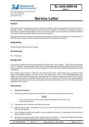
2. The electrical connection of P50 & J50 (Figure 1) must not be disconnected at this point in<br />
time. Look for signs of charring or discolouration of the connector housing. Inspect for signs<br />
of damage to the pitot or static lines in the near vicinity of the electrical connector.<br />
3. In accordance with the directions stated in the Compliance statement of this Service Bulletin,<br />
Part 2 of this Service Bulletin is to be carried out. If carrying out Part 2 of this Service Bulletin<br />
immediately, proceed to Part 2, Step 2.<br />
Figure 1 – View of connector P50.<br />
<strong>SB</strong>-<strong>GA8</strong>-<strong>2012</strong>-<strong>77</strong> Issue: 4 Date of Issue: 11.01.2013 Page 3 of 8
Part 2 - Wiring modification<br />
1. Remove the left hand wing tip from the aircraft. Wing tip removal instructions are provided in<br />
Section 57-30-00 of the Service Manual. NOTE: Take care as wiring to the Strobe/Nav light<br />
is still connected.<br />
2. The standard aircraft wiring to the heated pitot is shown in Figure 2. The modified wiring is<br />
shown in Figure 3.<br />
Figure 2 – Unmodified wiring to the pitot static tube assembly.<br />
Figure 3 - Modified wiring to the pitot static tube assembly.<br />
<strong>SB</strong>-<strong>GA8</strong>-<strong>2012</strong>-<strong>77</strong> Issue: 4 Date of Issue: 11.01.2013 Page 4 of 8
3. Discard connector housings P50 and J50, and cut-off the spade terminals.<br />
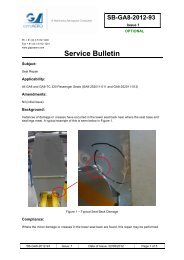
4. Fit item 2. Alternatively item 14 may be modified in accordance with Figure 4. This can be<br />
done by using a hacksaw. File away any “plastic” burring.<br />
Figure 4 - Dimensions of modified terminal strip.<br />
Figure 5 - Terminal Strip installed (item 2).<br />
<strong>SB</strong>-<strong>GA8</strong>-<strong>2012</strong>-<strong>77</strong> Issue: 4 Date of Issue: 11.01.2013 Page 5 of 8
T50<br />
Figure 6 - Ring terminals fitted.<br />
5. Crimp the ring terminals (item 8) to the wire leads.<br />
6. Screw wire FH1C14 and wire FH1B14 to one stud.<br />
7. Screw wire FH1D14 and wire FH1E14N to the second stud.<br />
8. Placard “T50” to be fixed in near vicinity of the terminal strip.<br />
9. Fit the terminal cover as shown in Figure 7. Use either item 1 or items 12 and 13 cut to length<br />
as shown in Figure 8.<br />
Figure 7 - Terminal Cover fitted (item 1).<br />
<strong>SB</strong>-<strong>GA8</strong>-<strong>2012</strong>-<strong>77</strong> Issue: 4 Date of Issue: 11.01.2013 Page 6 of 8
Figure 8 – Dimensions for modified cover.<br />
10. The wiring to the navigation light and strobe is to be checked. To ensure there is no possibility<br />
of chaffing as the wire passes through the lightening hole to the lamps a nylon stand-off, item<br />
9, is to be fitted using item 11 Refer to Figure 9.<br />
Figure 9<br />
Part 3 - Testing the Pitot-Heater & Pitot-Heat Caution Light System<br />
WARNING:<br />
REMOVE ANY PROTECTIVE COVERS FITTED TO THE PITOT STATIC TUBE.<br />
1. The pitot-heat caution system is functionally tested as follows:<br />
i. Switch on Bus 1 Master ensuring the CAUTION SYS 1 circuit breaker is pushed in.<br />
ii. With the pitot-heat switched off, check that the amber pitot-heat caution light is<br />
illuminated.<br />
iii. Observe the current draw for Bus 1. Switch on pitot-heat. The current draw for Bus 1<br />
should rise and indicate an increase of approximately 10A.<br />
iv. Check that amber caution light extinguishes.<br />
v. Immediately check the heater tube. It will begin to warm if operating correctly.<br />
<strong>SB</strong>-<strong>GA8</strong>-<strong>2012</strong>-<strong>77</strong> Issue: 4 Date of Issue: 11.01.2013 Page 7 of 8
CAUTION:<br />
ENSURE CAUTION WHILE TOUCHING THE TUBE TO AVOID BURNING OF<br />
HAND.<br />
2. If however the amber light remains on when the tube is operating correctly, the sensor board<br />
located in the electrical overhead panel or the wiring from that board to the Caution Unit is<br />
likely to be faulty.<br />
3. Switch off the Pitot Heat. Check that the amber pitot-heat caution light illuminates<br />
Part 4 - Testing the Strobe and the Nav Light<br />
CAUTION:<br />
AVOID LOOKING DIRECTLY AT THE STROBE LAMP.<br />
1. The Strobe and Nav lights are to be checked for operation after installing the nylon stand-off.<br />
Documentation:<br />
Update the aircraft log book to reflect incorporation of this Service Bulletin.<br />
Continuing Airworthiness:<br />
There are no additional continuing airworthiness requirements as part of the implementation of this<br />
Service Bulletin.<br />
Section 34-10-00 of the Service Manual as amended prior to the approval date of this Service Bulletin<br />
is to be altered in the future. Until a revision note is issued by <strong>GippsAero</strong>, the directions contained<br />
within this Service Bulletin for the testing of the pitot heater and heat caution light system shall be<br />
followed.<br />
Compliance Notice:<br />
Complete the Document Compliance Notice and return to <strong>GippsAero</strong> by mail, fax or email.<br />
<strong>SB</strong>-<strong>GA8</strong>-<strong>2012</strong>-<strong>77</strong> Issue: 4 Date of Issue: 11.01.2013 Page 8 of 8
DOCUMENT COMPLIANCE NOTICE<br />
Document:<br />
<strong>SB</strong>-<strong>GA8</strong>-<strong>2012</strong>-<strong>77</strong><br />
Issue 4<br />
Aircraft Serial Number:<br />
<strong>GA8</strong>-______________<br />
Service Bulletin <strong>SB</strong>-<strong>GA8</strong>-<strong>2012</strong>-<strong>77</strong> Issue 3 has been incorporated in the above aircraft.<br />
Date: ______________________________________<br />
___________________________________________<br />
Signed<br />
Print Name: _________________________________<br />
Please post or fax this compliance notice to:<br />
<strong>GippsAero</strong><br />
Attn: Technical Services<br />
P.O. Box 881<br />
Morwell Victoria 3840<br />
Australia<br />
Fax.: +61 03 5172 1201