SB-GA8-2005-26 - GippsAero
SB-GA8-2005-26 - GippsAero
SB-GA8-2005-26 - GippsAero

Create successful ePaper yourself
Turn your PDF publications into a flip-book with our unique Google optimized e-Paper software.
PO Box 881, Morwell, Victoria 3840, Australia<br />
Ph + 61 (0) 3 5172 1200<br />
Fax + 61 (0) 3 5172 1201<br />
www.gippsaero.com<br />
Service Bulletin<br />
<strong>SB</strong>-<strong>GA8</strong>-<strong>2005</strong>-<strong>26</strong><br />
Issue 3<br />
OPTIONAL<br />
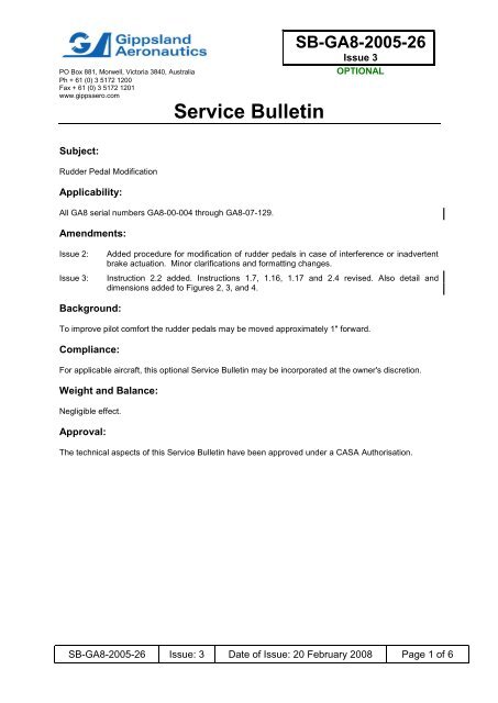
Subject:<br />
Rudder Pedal Modification<br />
Applicability:<br />
All <strong>GA8</strong> serial numbers <strong>GA8</strong>-00-004 through <strong>GA8</strong>-07-129.<br />
Amendments:<br />
Issue 2:<br />
Issue 3:<br />
Added procedure for modification of rudder pedals in case of interference or inadvertent<br />
brake actuation. Minor clarifications and formatting changes.<br />
Instruction 2.2 added. Instructions 1.7, 1.16, 1.17 and 2.4 revised. Also detail and<br />
dimensions added to Figures 2, 3, and 4.<br />
Background:<br />
To improve pilot comfort the rudder pedals may be moved approximately 1" forward.<br />
Compliance:<br />
For applicable aircraft, this optional Service Bulletin may be incorporated at the owner's discretion.<br />
Weight and Balance:<br />
Negligible effect.<br />
Approval:<br />
The technical aspects of this Service Bulletin have been approved under a CASA Authorisation.<br />
<strong>SB</strong>-<strong>GA8</strong>-<strong>2005</strong>-<strong>26</strong> Issue: 3 Date of Issue: 20 February 2008 Page 1 of 6
Parts:<br />
Item Part Number Description Qty<br />
1 <strong>GA8</strong>-272021-41 Brake master cylinder mounting<br />
bracket<br />
4<br />
2 <strong>GA8</strong>-325011-15 Steerage push rod 2<br />
3 MS21252-5RL Turnbuckle fork 2<br />
Parts Availability:<br />
Parts can be obtained as a kit directly from Gippsland Aeronautics.<br />
Labour:<br />
Tel.: +61 03 5172 1200<br />
Fax.: +61 03 5172 1201<br />
Email: spares@gippsaero.com<br />
Approximately 7 hours should be allocated for completing the work detailed in this Service Bulletin.<br />
Warranty:<br />
Gippsland Aeronautics participation is limited to the supply of parts, including freight, at the owner's<br />
expense.<br />
Instructions:<br />
1. Rudder Pedal Position Change Procedure<br />
NOTE:<br />
Refer to Figures 2 and 3 (page 5) for a comparison of the rudder pedal<br />
positions before and after completing this procedure.<br />
1.1. Remove the tailcone/rudder fairing.<br />
1.2. Disconnect both rudder control cables from the rudder horns.<br />
1.3. Remove the AN161-32RS turnbuckle forks from the now disconnected ends of the rudder<br />
control cables (refer to Figure 1).<br />
1.4. Remove the crew seats and kick panels to gain clear access around the rudder pedals.<br />
1.5. Disconnect brake cylinders from pedals and bracket. Disconnect the blank brake hoses and<br />
cylinders and remove the cylinders.<br />
1.6. Remove the brake cylinder mounting brackets and install new brackets (<strong>GA8</strong>-272021-41, Item<br />
1) in accordance with Figure 3.<br />
1.7. Adjust the overall length between the brake master cylinder attachment holes to 7.625"±0.06"<br />
and cut 0.125” off the top of the brake master cylinder threaded pushrods. If necessary, shorten<br />
the pushrod using a suitable file or hack saw and dress the thread. The thread length may be<br />
increased using a 5/16"-24 die. Label the modified brake master cylinders with <strong>SB</strong> <strong>GA8</strong>-<strong>2005</strong>-<br />
<strong>26</strong>-3. Alternatively, the brake master cylinder may be replaced by Gippsland Aeronautics part<br />
<strong>GA8</strong>-324023-41. Modify the co-pilot hydraulic master cylinder pushrods as per the brake master<br />
cylinders, and label the modified part with <strong>SB</strong> <strong>GA8</strong>-<strong>2005</strong>-<strong>26</strong>-3. Also, Gippsland Aeronautics part<br />
<strong>GA8</strong>-324023-43 may be used to replace non-modified hydraulic master cylinder.<br />
<strong>SB</strong>-<strong>GA8</strong>-<strong>2005</strong>-<strong>26</strong> Issue: 3 Date of Issue: 20 February 2008 Page 2 of 6
1.8. Raise and support the nose wheel clear of the ground.<br />
1.9. Remove the nose gear steerage pushrods and rod ends.<br />
1.10. Apply a sufficient quantity of suitable corrosion inhibitor, such as raw linseed oil, to completely<br />
coat the inner wall of the steerage pushrods, and drain any excess. Ensure outer surfaces are<br />
thoroughly clean of the corrosion inhibitor.<br />
1.11. Fit rod ends to new steerage pushrods (<strong>GA8</strong>-325011-15, Item 2).<br />
1.12. Adjust new steerage pushrods to an overall length of 10.75"±0.06" between rod end attachment<br />
holes. Check that thread engagement is in safety and tighten one check nut. Set the other nut<br />
to the position of rod end, and remove the rod end.<br />
1.13. Reinstall the nose wheel steerage pushrods by passing the free ends through the firewall,<br />
maintaining the position of the check nuts. Reinstall the rod ends and reattach to the rudder<br />
pedals using existing hardware. Tighten the check nuts.<br />
1.14. Reinstall the brake cylinders to the pedal assemblies, reconnect brake hoses and bleed the<br />
system in accordance with <strong>GA8</strong> Service Manual section 32-40-00.<br />
1.15. Position the rudder pedals and nose steering to the neutral position.<br />
NOTE:<br />
Rudder pedals will adopt a position angled slightly forward as shown in<br />
Figure 3.<br />
1.16. In the rear of the aircraft, replace the AN161-32RS turnbuckle forks with MS21252-5RL (Item 3)<br />
turnbuckle forks (long), if required, so as to achieve a rudder cable tension of 40±5lb.<br />
1.17 Reattach turnbuckle assemblies to the rudder horns using existing hardware and with the<br />
rudder and rudder pedals in the neutral position. Tension the rudder cables to 40±5 lb. Reuse<br />
the AN161-32RS turnbuckle forks if the tension cannot be achieved with the MS21252-5RL<br />
forks.<br />
1.18. Cycle rudder pedals through their full travel. Ensure that nose wheel stop clearances at full<br />
travel are 0.06" with the rudder on its stops, and that the rudder pedals achieve their full travel<br />
without interference. It may be necessary to make adjustments to the nose wheel steerage<br />
pushrod ends to achieve freedom from interference and adjustment to the nose wheel stops to<br />
achieve correct clearance.<br />
NOTE:<br />
If full travel of rudder pedals with freedom from interference cannot be<br />
achieved, or inadvertent brake actuation occurs during cycling of the rudder<br />
pedals due to interference of the pedals and crank arms, complete<br />
Procedure 2 (Rudder Pedal Modification Procedure) for all rudder pedals<br />
prior to repeating step 18 and completing the remaining steps of this<br />
procedure.<br />
1.19. Lock turnbuckle barrels, clevis pins and the steering linkage rod ends for safety.<br />
1.20. Lower the nose wheel to the ground.<br />
1.21. Conduct a taxi test, turning the aircraft in both directions at full pedal travel. If inadvertent brake<br />
drag occurs, the steerage pushrods will need to be adjusted slightly to lengthen the rod until the<br />
system is free from inadvertent brake drag.<br />
NOTE:<br />
If brake drag occurs due to interference between the pedals and crank arms,<br />
complete Procedure 2 (Rudder Pedal Modification Procedure) for all rudder<br />
pedals prior to repeating step 21 and completing the remaining steps of this<br />
procedure.<br />
1.22. Record completion of Procedure 1 in the Document Compliance Notice.<br />
<strong>SB</strong>-<strong>GA8</strong>-<strong>2005</strong>-<strong>26</strong> Issue: 3 Date of Issue: 20 February 2008 Page 3 of 6
Turnbuckle<br />
Fork<br />
Figure 1: Directional Control Circuit - Aft<br />
Turnbuckle<br />
Barrel<br />
Brake Master<br />
Cylinder<br />
7.625” <br />
0.06”<br />
Crank Arm<br />
Figure 2: Original Configuration<br />
<strong>SB</strong>-<strong>GA8</strong>-<strong>2005</strong>-<strong>26</strong> Issue: 3 Date of Issue: 20 February 2008 Page 4 of 6
Trim 1/8” off brake<br />
master cylinder<br />
pushrod<br />
Brake Master<br />
Cylinder<br />
Crank Arm<br />
2.5625”<br />
Figure 3: Position after Service Bulletin Incorporation<br />
2. Rudder Pedal Modification Procedure<br />
NOTE:<br />
Complete this procedure if brake actuation occurs during cycling of the<br />
rudder pedals (Step 18, Procedure 1 - Rudder Pedal Position Change<br />
Procedure) due to interference of the pedals and crank arms.<br />
2.1. Remove the rudder pedals.<br />
2.2. Trim the rudder pedal in accordance with Figure 4.<br />
2.3. Machine a radius in each pedal in accordance with Figures 4 to 6.<br />
2.4. Ensure that all sharp edges are removed using an appropriate file and label the forward side of<br />
each modified rudder pedal with “<strong>SB</strong>-<strong>GA8</strong>-<strong>2005</strong>-<strong>26</strong>-3”.<br />
2.5. Reinstall the rudder pedals using existing hardware.<br />
2.6. Record completion of Procedure 2 in the Document Compliance Notice.<br />
2.7. Continue with remaining steps of Procedure 1 (Rudder Pedal Position Change Procedure),<br />
repeating appropriate steps to ensure freedom of interference of pedals with crank arms.<br />
<strong>SB</strong>-<strong>GA8</strong>-<strong>2005</strong>-<strong>26</strong> Issue: 3 Date of Issue: 20 February 2008 Page 5 of 6
Minimal Material<br />
Removed for<br />
clearance of<br />
master cylinders<br />
Figure 4<br />
ENSURE A SMOOTH<br />
SURFACE TRANSITION<br />
ALONG RIB OF PEDAL<br />
AFFECTED<br />
AREA<br />
Figure 5<br />
ENSURE THAT THE MACHINED<br />
RADIUS DOES NOT CONTACT<br />
RIB OF PEDAL FACE<br />
Figure 6<br />
Documentation:<br />
Update aircraft log book to reflect incorporation of this Service Bulletin.<br />
Compliance Notice:<br />
Complete the Document Compliance Notice and return to Gippsland Aeronautics by fax or mail.<br />
<strong>SB</strong>-<strong>GA8</strong>-<strong>2005</strong>-<strong>26</strong> Issue: 3 Date of Issue: 20 February 2008 Page 6 of 6
DOCUMENT COMPLIANCE NOTICE<br />
Document:<br />
Service Bulletin <strong>SB</strong>-<strong>GA8</strong>-<strong>2005</strong>-<strong>26</strong>, Issue 3<br />
<br />
<br />
Completion of Procedure 1 (Rudder Pedal Position Change Procedure)<br />
Completion of Procedure 2 (Rudder Pedal Modification Procedure)<br />
Aircraft Serial Number:<br />
<strong>GA8</strong>-______________<br />
Service Bulletin <strong>SB</strong>-<strong>GA8</strong>-<strong>2005</strong>-<strong>26</strong> Issue 03 has been incorporated for the above<br />
aircraft.<br />
Date _______________________________<br />
___________________________________<br />
Signed<br />
Print Name __________________________<br />
Please post or fax this compliance notice to:<br />
Gippsland Aeronautics<br />
Attn: Technical Services<br />
P.O. Box 881<br />
Morwell Victoria 3840<br />
Australia<br />
Fax.: +61 03 5172 1201