

"WINNER II Channel Models", ver 1.1, Sept
"WINNER II Channel Models", ver 1.1, Sept
"WINNER II Channel Models", ver 1.1, Sept

Create successful ePaper yourself
Turn your PDF publications into a flip-book with our unique Google optimized e-Paper software.
<strong>WINNER</strong> <strong>II</strong> D<strong>1.1</strong>.2 V<strong>1.1</strong><br />
d<br />
( arctan( y x ) −ϕ )<br />
2 2<br />
'<br />
xu<br />
+ yu<br />
cos<br />
u u n,<br />
m<br />
u,<br />
n,<br />
m<br />
= , (4.18)<br />
sinϕn,<br />
m<br />
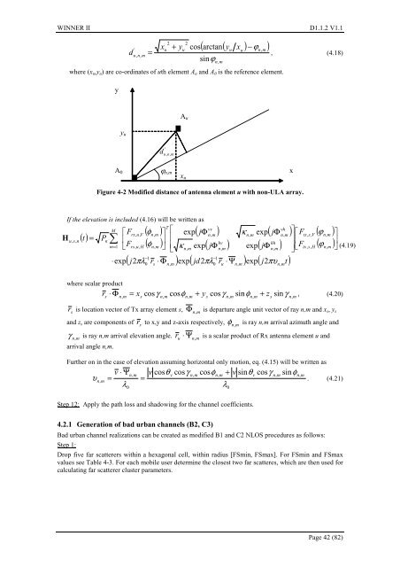
where (x u ,y u ) are co-ordinates of uth element A u and A 0 is the reference element.<br />
y<br />
A u<br />
y u<br />
'<br />
d<br />
ud , n u<br />
,’<br />
m<br />
A 0<br />
ϕ n,m<br />
x u<br />
x<br />
Figure 4-2 Modified distance of antenna element u with non-ULA array.<br />
H<br />
If the elevation is included (4.16) will be written as<br />
u,<br />
s,<br />
n<br />
( t)<br />
=<br />
P<br />
M<br />
∑<br />
n<br />
m=<br />
1<br />
⎡<br />
⎢<br />
⎣<br />
⋅exp<br />
T<br />
vv<br />
vh<br />
Frx<br />
, u,<br />
V<br />
( φn,<br />
m<br />
) ⎤ ⎡ exp( jΦ<br />
n,<br />
m<br />
) κ<br />
n,<br />
m<br />
exp( jΦ<br />
n,<br />
m<br />
)<br />
F ( )<br />
hv<br />
hh<br />
rx,<br />
u,<br />
H<br />
φ<br />
⎥ ⎢<br />
n,<br />
m ⎦ ⎢<br />
⎣<br />
κ<br />
n,<br />
m<br />
exp( jΦ<br />
n,<br />
m<br />
) exp( jΦ<br />
n,<br />
m<br />
)<br />
−1<br />
−1<br />
( j2πλ<br />
r ⋅ Φ ) exp( jd2πλ<br />
r ⋅ Ψ ) exp( j2πυ<br />
t)<br />
0<br />
s<br />
n,<br />
m<br />
0<br />
u<br />
n,<br />
m<br />
n,<br />
m<br />
⎤⎡F<br />
⎥⎢<br />
⎥⎣F<br />
⎦<br />
tx,<br />
s,<br />
V<br />
tx,<br />
s,<br />
H<br />
( ϕn,<br />
m<br />
)<br />
( ϕ )<br />
n,<br />
m<br />
⎤<br />
⎥<br />
⎦<br />
(4.19)<br />
where scalar product<br />
⋅ Φ = x cosγ cosφ<br />
+ y cosγ<br />
sinφ<br />
+ z γ , (4.20)<br />
r<br />
s n, m s n,<br />
m n,<br />
m s n,<br />
m n,<br />
m s<br />
sin<br />
n,<br />
m<br />
r<br />
s<br />
is location vector of Tx array element s,<br />
Φ<br />
n, m<br />
is departure angle unit vector of ray n,m and x s , y s<br />
and z s are components of r<br />
s<br />
to x,y and z-axis respectively, φ<br />
n, m<br />
is ray n,m arrival azimuth angle and<br />
γ<br />
n,m<br />
is ray n,m arrival elevation angle. r<br />
u<br />
Ψn,<br />
m<br />
arrival angle n,m.<br />
⋅ is a scalar product of Rx antenna element u and<br />
Further on in the case of elevation assuming horizontal only motion, eq. (4.15) will be written as<br />
υ<br />
n,<br />
m<br />
v ⋅ Ψn,<br />
m<br />
v cosθ<br />
v<br />
cosγ<br />
n,<br />
m<br />
cosφn,<br />
m<br />
+ v sinθv<br />
cosγ<br />
=<br />
λ<br />
λ<br />
0<br />
0<br />
n,<br />
m<br />
sinφ<br />
= . (4.21)<br />
Step 12: Apply the path loss and shadowing for the channel coefficients.<br />
n,<br />
m<br />
4.2.1 Generation of bad urban channels (B2, C3)<br />
Bad urban channel realizations can be created as modified B1 and C2 NLOS procedures as follows:<br />
Step 1:<br />
Drop five far scatterers within a hexagonal cell, within radius [FSmin, FSmax]. For FSmin and FSmax<br />
values see Table 4-3. For each mobile user determine the closest two far scatteres, which are then used for<br />
calculating far scatterer cluster parameters.<br />
Page 42 (82)


