water storage tank - Balmoral Group
water storage tank - Balmoral Group
water storage tank - Balmoral Group

You also want an ePaper? Increase the reach of your titles
YUMPU automatically turns print PDFs into web optimized ePapers that Google loves.
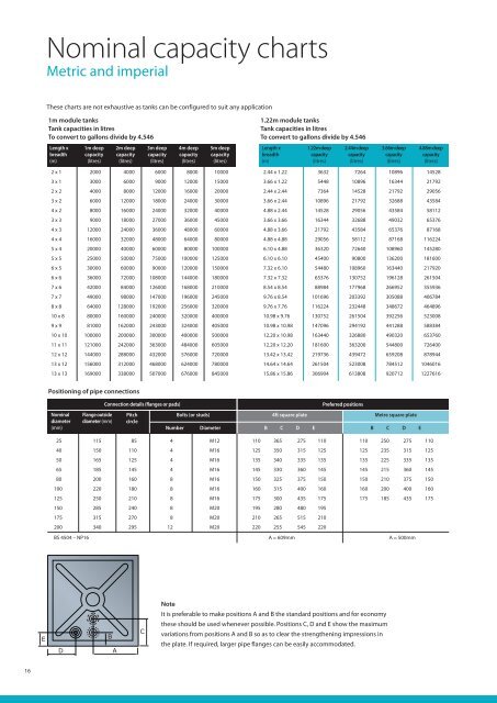
Nominal capacity charts<br />
Metric and imperial<br />
These charts are not exhaustive as <strong>tank</strong>s can be configured to suit any application<br />
1m module <strong>tank</strong>s<br />
Tank capacities in litres<br />
To convert to gallons divide by 4.546<br />
1.22m module <strong>tank</strong>s<br />
Tank capacities in litres<br />
To convert to gallons divide by 4.546<br />
Length x<br />
breadth<br />
(m)<br />
1m deep<br />
capacity<br />
(litres)<br />
2m deep<br />
capacity<br />
(litres)<br />
3m deep<br />
capacity<br />
(litres)<br />
4m deep<br />
capacity<br />
(litres)<br />
5m deep<br />
capacity<br />
(litres)<br />
Length x<br />
breadth<br />
(m)<br />
1.22m deep<br />
capacity<br />
(litres)<br />
2.44m deep<br />
capacity<br />
(litres)<br />
3.66m deep<br />
capacity<br />
(litres)<br />
4.88m deep<br />
capacity<br />
(litres)<br />
2 x 1 2000 4000 6000 8000 10000<br />
3 x 1 3000 6000 9000 12000 15000<br />
2 x 2 4000 8000 12000 16000 20000<br />
3 x 2 6000 12000 18000 24000 30000<br />
4 x 2 8000 16000 24000 32000 40000<br />
3 x 3 9000 18000 27000 36000 45000<br />
4 x 3 12000 24000 36000 48000 60000<br />
4 x 4 16000 32000 48000 64000 80000<br />
5 x 4 20000 40000 60000 80000 100000<br />
5 x 5 25000 50000 75000 100000 125000<br />
6 x 5 30000 60000 90000 120000 150000<br />
6 x 6 36000 72000 108000 144000 180000<br />
7 x 6 42000 84000 126000 168000 210000<br />
7 x 7 49000 98000 147000 196000 245000<br />
8 x 8 64000 128000 192000 256000 320000<br />
10 x 8 80000 160000 240000 320000 400000<br />
9 x 9 81000 162000 243000 324000 405000<br />
10 x 10 100000 200000 300000 400000 500000<br />
11 x 11 121000 242000 363000 484000 605000<br />
12 x 12 144000 288000 432000 576000 720000<br />
13 x 12 156000 312000 468000 624000 780000<br />
13 x 13 169000 338000 507000 676000 845000<br />
2.44 x 1.22 3632 7264 10896 14528<br />
3.66 x 1.22 5448 10896 16344 21792<br />
2.44 x 2.44 7364 14528 21792 29056<br />
3.66 x 2.44 10896 21792 32688 43584<br />
4.88 x 2.44 14528 29056 43584 58112<br />
3.66 x 3.66 16344 32688 49032 65376<br />
4.88 x 3.66 21792 43584 65376 87168<br />
4.88 x 4.88 29056 58112 87168 116224<br />
6.10 x 4.88 36320 72640 108960 145280<br />
6.10 x 6.10 45400 90800 136200 181600<br />
7.32 x 6.10 54480 108960 163440 217920<br />
7.32 x 7.32 65376 130752 196128 261504<br />
8.54 x 8.54 88984 177968 266952 355936<br />
9.76 x 8.54 101696 203392 305088 406784<br />
9.76 x 7.76 116224 232448 348672 464896<br />
10.98 x 9.76 130752 261504 392256 523008<br />
10.98 x 10.98 147096 294192 441288 588384<br />
12.20 x 10.98 163440 326880 490320 653760<br />
12.20 x 12.20 181600 363200 544800 726400<br />
13.42 x 13.42 219736 439472 659208 878944<br />
14.64 x 14.64 261504 523008 784512 1046016<br />
15.86 x 15.86 306904 613808 920712 1227616<br />
Positioning of pipe connections<br />
Connection details (flanges or pads)<br />
Preferred positions<br />
Nominal<br />
diameter<br />
(mm)<br />
Flange outside<br />
diameter (mm)<br />
Pitch<br />
circle<br />
Number<br />
Bolts (or studs)<br />
Diameter<br />
4ft square plate<br />
B C D E<br />
Metre square plate<br />
B C D E<br />
25 115 85 4 M12 110 365 275 110 110 250 275 110<br />
40 150 110 4 M16 125 350 315 125 125 235 315 125<br />
50 165 125 4 M16 135 340 335 135 135 225 335 135<br />
65 185 145 4 M16 145 330 360 145 145 215 360 145<br />
80 200 160 8 M16 150 325 375 150 150 210 375 150<br />
100 220 180 8 M16 160 315 400 160 160 200 400 160<br />
125 250 210 8 M16 175 300 435 175 175 185 435 175<br />
150 285 240 8 M20 195 280 480 195<br />
175 315 270 8 M20 210 265 515 210<br />
200 340 295 12 M20 220 255 545 220<br />
BS 4504 – NP16 A = 609mm A = 500mm<br />
Note<br />
It is preferable to make positions A and B the standard positions and for economy<br />
E<br />
D<br />
B<br />
A<br />
C<br />
these should be used whenever possible. Positions C, D and E show the maximum<br />
variations from positions A and B so as to clear the strengthening impressions in<br />
the plate. If required, larger pipe flanges can be easily accommodated.<br />
16