PMS-920 - Aplisens SA
PMS-920 - Aplisens SA
PMS-920 - Aplisens SA

You also want an ePaper? Increase the reach of your titles
YUMPU automatically turns print PDFs into web optimized ePapers that Google loves.
User manual for meter with U/I input <strong>PMS</strong>-<strong>920</strong><br />
If t A ,t B ,t C or t D (when input signal stay in zone A or zone B) are lower than parameters “t on”<br />
or “toFF”, the relay will not change his state (see points A and C, Figure 6.6 a, d, e).<br />
The state of relay output while the input value exceeds the border values (points A, B, C,<br />
D) is described by parameter “modE”. The relay can be turned on (“modE” = ”on”), or<br />
turned off (“modE” = ”oFF”) when input signal value is contained in zone A (Figure 6.6 a).<br />
The parameter “AL” allow user to set the relay output behaviour in critical situations (e.<br />
g. Input values exceeds permissible measurement range). User can select that the relays<br />
will be turned on, turned off,or not changed in critical situations.<br />
All parameters connected with relay outputs are described in paragraph ”rEL1” menu.<br />
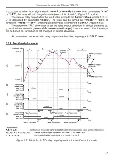
6.3.2. Two thresholds mode<br />
displayed value<br />
t A<br />
t B<br />
t C<br />
measure<br />
t D<br />
d signal<br />
C<br />
t E<br />
“HYSt” parameter<br />
B ON<br />
a)<br />
zone B C OFF<br />
C ON<br />
E<br />
zone A<br />
A<br />
B<br />
D<br />
E OFF<br />
“SEtP” or “SEt2”<br />
parameter<br />
“HYSt” parameter<br />
zone B<br />
b)<br />
c)<br />
relay state<br />
(modE = in<br />
t on = 0<br />
toFF = 0)<br />
relay state<br />
(modE = out<br />
t on = 0<br />
toFF = 0)<br />
closed<br />
open<br />
B OFF<br />
E ON<br />
time<br />
open<br />
closed<br />
time<br />
time<br />
d)<br />
e)<br />
relay state<br />
(modE = in<br />
t on > 0<br />
toFF > 0)<br />
relay state<br />
(modE = out<br />
t on > 0<br />
toFF > 0)<br />
“t on” parameter<br />
“toFF” parameter<br />
closed<br />
open<br />
“toFF” parameter “t on” parameter<br />
closed<br />
open<br />
“t on” parameter “toFF” parameter<br />
time<br />
time<br />
Objaśnienie:<br />
A, B, C, D, E - points where measured signal exceeds border values (expected value ± allowed deviation)<br />
B ON ,B OFF ,C ON ,C OFF ,E ON ,E OFF - relays state changes moments: (for “t on” > 0, “toFF” > 0)<br />
t A , t B , t C , t D , t E<br />
- time periods while input signal is in zone A or zone B<br />
Figure 6.7. Principle of LED/relay output operation for two thresholds mode<br />
19