NAMC-STM1/4 Telecom AMC Module Technical Reference ... - NAT
NAMC-STM1/4 Telecom AMC Module Technical Reference ... - NAT
NAMC-STM1/4 Telecom AMC Module Technical Reference ... - NAT

You also want an ePaper? Increase the reach of your titles
YUMPU automatically turns print PDFs into web optimized ePapers that Google loves.
<strong>N<strong>AMC</strong></strong>-<strong>STM1</strong>/4 – <strong>Technical</strong> <strong>Reference</strong> Manual<br />
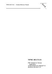
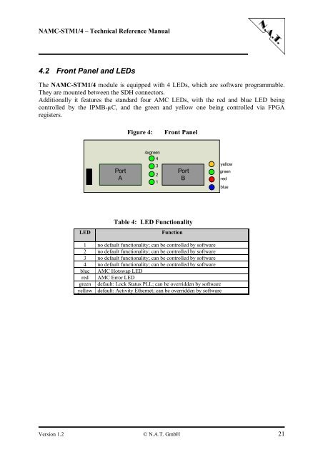
4.2 Front Panel and LEDs<br />
The <strong>N<strong>AMC</strong></strong>-<strong>STM1</strong>/4 module is equipped with 4 LEDs, which are software programmable.<br />
They are mounted between the SDH connectors.<br />
Additionally it features the standard four <strong>AMC</strong> LEDs, with the red and blue LED being<br />
controlled by the IPMB-µC, and the green and yellow one being controlled via FPGA<br />
registers.<br />
LED<br />
Port<br />
A<br />
Figure 4: Front Panel<br />
4xgreen<br />
4<br />
2<br />
1<br />
Port<br />
B<br />
Table 4: LED Functionality<br />
3<br />
Function<br />
1 no default functionality; can be controlled by software<br />
2 no default functionality; can be controlled by software<br />
3 no default functionality; can be controlled by software<br />
4 no default functionality; can be controlled by software<br />
blue <strong>AMC</strong> Hotswap LED<br />
red <strong>AMC</strong> Error LED<br />
green default: Lock Status PLL; can be overridden by software<br />
yellow default: Activity Ethernet; can be overridden by software<br />
Version 1.2 © N.A.T. GmbH 21<br />
yellow<br />
green<br />
red<br />
blue